

Page 1
Application Bulletin 287 e
Installation Instructions of TitrIC 3
861 Dual Channel Advanced Compact IC with 815 USB
Sample Processor
815
Metrohm
800 Dosino
20
mL
VENT
HNO
712
800 Dosino
50
Metrohm
Metrohm
800 Dosino
10
mL
mL
VENT
VENT
x
800
3
809
3
2.861.0010
2.861.0020
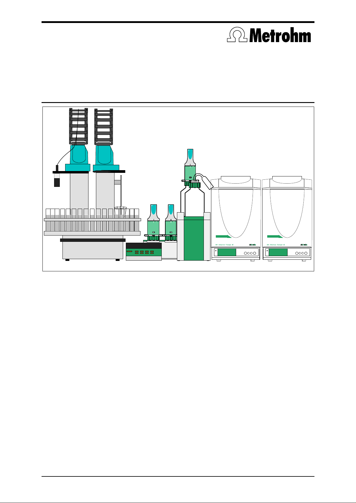
The TitrIC 3 System with two 861 Compact ICs, 815 Robotic USB Sample Processor and 809 Titrando
The TitrIC 3 System is used for the fully automatic analysis of water samples using direct measurement, titration and ion chromatography. The caps of the air protected sample beakers are discovered
with the DIS-COVER function of the 815 and the following measured values are determined in a very
short time: temperature, conductivity, pH, acid capacity and, in parallel, the concentrations of the
individual anions and cations. Further Metrohm instruments can be incorporated in the existing system
at any time and used to measure additional parameters.
Analytical sequence
1. Conductivity is measured in the sample vessel on the sample changer.
2. First sample transfer to the two 861 Advanced Compact ICs.
3. The IC measurements are started automatically.
4. Second sample transfer to the external cell of the 815 Robotic Sample Processor.
5. Temperature, pH and acid capacity (p and m values) are determined.
The whole procedure is controlled by the TitrIC software: The user enters the sample position and
sample identification, IC system and tiamo method, after which TitrIC transfers all the relevant
information to tiamo and IC Net. When the measurement has been concluded, TitrIC automatically
generates a joint report containing all results. This report can be printed out or produced as an Excel
table.
Version 1.0
Page 2

Application Bulletin 287 e
Installation Instructions of TitrIC 3
Page 2/16
Table of contents
1 Delivery package...............................................................................................................................3
2 Installation.........................................................................................................................................4
2.1 815 Robotic Sample Processor..................................................................................................4
2.2 712 Conductometer (2.712.0010) .............................................................................................. 4
2.3 Titrando (2.809.0010).................................................................................................................4
2.4 Dosino holder (6.2055.100)........................................................................................................4
2.5 861 Advanced Compact IC (2.861.00x0)................................................................................... 4
3 Cable connections ............................................................................................................................ 5
4 Tubing connections...........................................................................................................................7
4.1 External cell................................................................................................................................ 7
4.2 Installation of the 10 mL and 50 mL Dosing Units...................................................................... 8
4.3 Overview of all the tubing connections....................................................................................... 9
5 Miscellaneous ................................................................................................................................. 11
5.1 Membrane Pumps of 815......................................................................................................... 11
5.2 Stirrer........................................................................................................................................11
5.3 Length of the aspiration tips in the external cell....................................................................... 11
5.4 Electrodes................................................................................................................................. 11
6 Software..........................................................................................................................................12
6.1 Installation of the software........................................................................................................ 12
6.2 Configuration of tiamo .............................................................................................................. 12
6.2.1 Devices ..............................................................................................................................12
6.2.2 Swing Head configuration.................................................................................................. 12
6.2.3 Special beaker definition.................................................................................................... 13
6.2.4 Lift positions.......................................................................................................................13
6.2.5 Solutions............................................................................................................................ 13
6.2.6 Electrodes..........................................................................................................................14
6.2.7 Methods .............................................................................................................................14
6.2.8 Configuration of the export template..................................................................................15
6.3 Configuration of IC Net.............................................................................................................16
6.4 Configuration of TitrIC .............................................................................................................. 16
Page 3

Application Bulletin 287 e
Installation Instructions of TitrIC 3
Page 3/16
1 Delivery package
- delivered with TitrIC 3 package:
Number Article no. Article designation
IC
1 2.861.0020 861 Advanced Compact IC «MSM II» (anions)
1 2.861.0010 861 Advanced Compact IC (cations)
1 2.145.0320 Edgeport/4 USB Converter
Sample processor
1 2.815.0110 815 Robotic Titrosampler
2 2.786.0040 Swing Head
1 6.1462.050 Titration head
1 6.1462.080 Robotic Arm DIS-COVER
1 6.1808.170 Distributor Rinse/Aspirate
Conductometry
1 2.712.0010 712 Conductometer
1 6.0912.110 Conductivity measuring cell made of PP, with Pt 1000
1 6.2125.110 Cable to Edgeport USB Converter
p and m value titration (pH measurement)
1 2.809.0010 Titrando
1 6.0257.000 Aquatrode; combined pH glass electrode (with temperature measurement)
1 6.2151.000 Cable USB A – mini-DIN 8P
Liquid Handling
3 2.800.0010 800 Dosino
1 6.3032.210 807 Dosing Unit, glass, 10 mL
1 6.3032.220 807 Dosing Unit, glass, 20 mL
1 6.3032.250 807 Dosing Unit, glass, 50 mL
1 6.2055.100 Dosino holder
2 6.1608.030 Glass bottle GL45 1L (round)
2 6.5620.000 Connecting set for Dosing Unit: Dosino port 4
2 6.2744.080 Coupling M6-UNF 10/32 (Dosing Unit – IC screw)
1 6.2744.070 Pressure screw made of PEEK, short
2 6.1543.080 Aspiration tip 1.5 / 240 mm
1 6.1602.160 Eluent bottle attachment GL45
1 6.1609.000 Absorber tube
External cell
1 2.802.0020 802 Rod Stirrer
1 6.2001.070 Stand support for 804
1 6.1414.060 Titration vessel lid micro
1 6.1415.220 Titration vessel
7 6.2730.030 Stopper with nipple and O-ring
2 6.2730.080 Screw nipple
1 6.2730.020 Septum stopper
1 6.2730.070 Screw nipple M16/8mm
1 6.2730.060 Screw nipple for electrodes
1 6.1543.170 Aspiration tip M8
Connection tubings
1 6.1805.510 Connection tubing FEP, L = 60 cm, 2 x M8 thread
3 6.1805.030 Connection tubing FEP, L = 150 cm, 2 x M6 thread
1 6.1803.020 PTFE capillary, L = 5 m, i.d.= 0.97 mm
Software
1 6.6056.112 tiamo 1.1 full
- optional accessories:
1 6.2041.xxx Sample rack made of PVC
1 6.1432.xxx Sample beaker
1 6.1006.xxx Anion column Metrosep A Supp x
1 6.1006.xxx Guard column Metrosep A Supp x
1 6.1010.xxx Cation column Metrosep C x
1 6.1010.xxx Guard column Metrosep C x
1 2.853.0010 853 MCS CO2 Suppressor
1 2.861.0500 Column Oven for 861
1 6.2323.000 Storage solution
1 6.2308.020 Electrolyte solution (3 mol/L KCl)
1 6.2301.060 Conductivity standard
1 6.2307.100/110/120 Buffer solutions 500 mL, pH 4 / 7 / 9
1 6.2307.230 Buffer solutions 3 x 10 x 30mL of pH 4 / 7 / 9
Page 4

Application Bulletin 287 e
Installation Instructions of TitrIC 3
Page 4/16
2 Installation
The following is a detailed description of the TitrIC 3 System's installation.
We strongly recommend that the individual steps are carried out in the order given below!
2.1 815 Robotic Sample Processor
The sample processor is placed at the side at which it is most easily accessible. Please note that the
following procedure refers exclusively to the version in which the 815 Robotic Sample Processor is
located at the left-hand side of the system.
On the right-hand side of the 815 Robotic Sample Processor, attach the stand support
(6.2001.070) without the horizontal brace to the tower of the 815 (hexagon screw beneath
membrane pump 1). The brace will be installed later.
Mount both Swing Heads (2.786.0010) onto the 815 (see Installation Instructions 2.2.7, p 19).
Do not screw the titration head (6.1462.070) nor the titration arm onto the Swing Head!
The Sample Rack supplied is screwed onto the 815.
In the vicinity of the 815 the two canisters (standard equipment of 815) are placed on the
floor: One 10 L canister is used as a waste container, the second as a reservoir for deionized
(DI) water used for rinsing the external cell.
From the smaller opening of the canisters containing DI water, an M8 PTFE tubing connection
of suitable length is led to the connection box made of white plastic of membrane pump 1 /
tower 1 and connected.
From the front opening of the waste canister an M8 PTFE tubing connection of suitable length
is led directly to membrane pump 1 / tower 2 (black plastic) and connected.
A more detailed description is given in the Instructions for Use of the 815 Robotic Sample Processor.
2.2 712 Conductometer (2.712.0010)
The 712 Conductometer is placed directly to the right of the 815 Robotic Sample Processor and in
front of the stand support. For detailed information about the usage check the Instructions of Use of
the 712. It is recommended to carry out the calibration of the cell constant manually and before tiamo
is started up. Consult thereto the Installation Instructions of the 712 Conductometer, chapter 4.4.3. But
firstly the 712 has to be registered in the configuration of tiamo so that the calibration can be stored.
Thereto the calibration should be made later when the 712 is registered and tiamo shut down.
2.3 Titrando (2.809.0010)
Directly to the right of the 712 Conductometer, place the Titrando with the two bottles of the titration
solution (0.1 M HCl, at the rear, with 20 mL Dosing Unit and 800 Dosino) and the acidification solution
(1 M HNO
, at the front, with eluent bottle attachment).
3
2.4 Dosino holder (6.2055.100)
The Dosino holder (6.2055.100) is placed behind the Titrando and the 712 Conductometer; the 50 mL
(6.3032.250) and 10 mL (6.3032.210) Dosing Units are screwed on t o this holder at a later stage.
2.5 861 Advanced Compact IC (2.861.00x0)
Place the 861 Advanced Compact IC for cations (2.861.0010) to the right of the Titrando. To the right
of the 861 for cations, place the 861 Advanced Compact IC «MSM» for anions (2.861.0020). The two
instruments can already be installed. Please consult the Instructions for Use for the Advanced Compact IC instruments.
Page 5

Application Bulletin 287 e
Installation Instructions of TitrIC 3
Page 5/16
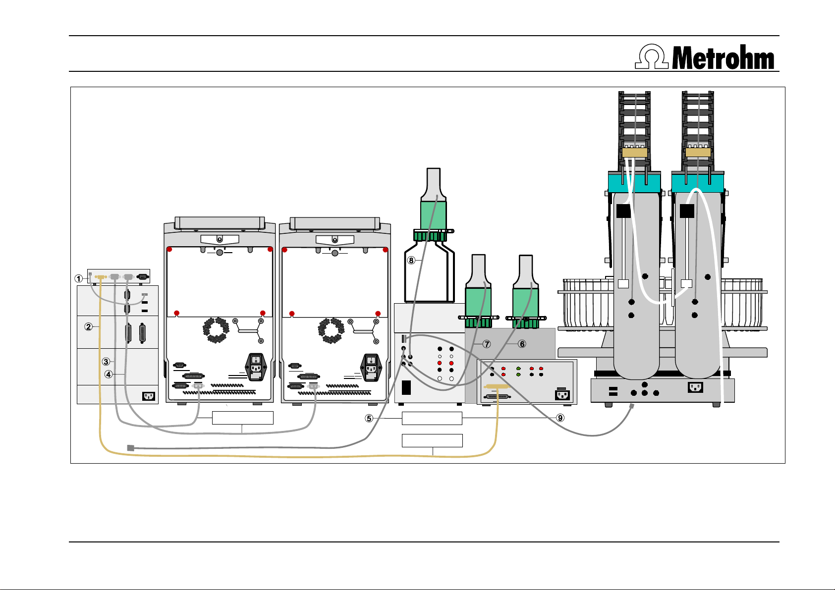
3 Cable connections
The numbers given here (
) refer to the drawing on the next page.
First all the power cables are connected to the instruments. Both the instruments and the PC remain
switched off.
USB cable from Edgeport to PC – supplied with USB Converter Edgeport/4 (2.145.0320)
RS cable (6.2125.110) from 712 Conductometer to Edgeport port 1
RS cable (6.2134.100) from 2.861.0020 IC to Edgeport port 2 – supplied with 861
RS cable (6.2134.100) from 2.861.0010 IC to Edgeport port 3 – supplied with 861
USB cable (6.2151.000) from PC to 809 Controller, do not connect!
MSB cable from Dosino 800, 50 mL (anions) to 809 MSB 1, do not connect!
MSB cable from Dosino 800, 10 mL (cations) to 809 MSB 2, do not connect!
MSB cable from Dosino 800, 20 mL (0.1 M HCl) to 809 MSB 3, do not connect!
USB cable (6.2151.000) from 809 to 815 Controller – supplied with 815, do not connect!
Page 6
Application Bulletin 287 e
Installation Instructions of TitrIC 3
Page 6/16
Waste A
Waste B
Waste A
Waste B
Ext.
Pump 2
Stirrer
Analog Output
Detector Block
Remote
RS 232
Made by Metrohm Herisau Switzerland
Fuse
100-120V:
1,0A(T)
220-240V:
0,5A(T)
6.2134.100
Analog Output
Detector Block
USB
MSB
Temp.
Ref.
Ind.
Pol.
Remote
RS 232
Fuse
100-120V:
1,0A(T)
220-240V:
0,5A(T)
Made by Metrohm Herisau Switzerland
Controller
1
6.2151.000
6.2134.080
Cable connections of the TitrIC 3 System
1
RS 232 C
Remote
USB
Contr.
MSB
2
3
Page 7

Application Bulletin 287 e
Installation Instructions of TitrIC 3
Page 7/16
4 Tubing connections
4.1 External cell
The numbers given here (
In the next step the external cell is prepared. The following components are inserted in the titration
vessel lid (6.1414.060):
The small 6.2730.030 stoppers (with the black rubber ring) are screwed loosely into openings 1, 2, 3, 5
and 7 and fixed in position when the buret tips, etc. are inserted.
The large 6.2730.080 stoppers are screwed into openings 4 and 8 and the screw nipple (6.2730.070)
into opening 9.
The titration vessel lid is attached to the stand support (6.2001.070) using opening 10, fixed at the
required height with the clamping ring and the horizontal brace of the stand support is mounted on the
815 with the socket head screw.
6.2730.070
screw nipple
) and «opening 1,...» refer to the drawing below.
,…
6.2730.030
stopper
8
10
6.2730.080
screw nipple
1
2
3
9
4
7
5
6
6.2740.020
rinsing nozzle
Numbers and connections on the titration vessel lid (6.1414.060)
The PTFE aspiration tip (6.1543.170, M8) is inserted in opening 1 and connected to
membrane pump 1 / tower 2 of the 815 with the M8 PTFE tubing connection (6.1805.510).
The rinsing nozzle (6.2740.020, supplied with 815) is inserted into opening 2, which is
connected to membrane pump 1 / tower 1 of the 815 with the FEP tubing connection
(6.1805.060, supplied with 815).
The buret tip (6.1543.200) is inserted through opening 3 and connected to port 1 of the 20 mL
Dosing Unit (0.1 M HCl) with the FEP tubing connection (6.1805.100, supplied with 807).
This is where the pH electrode will later be inserted.
The rinsing nozzle (6.2740.020, supplied with 815) is inserted into opening 5, which is
connected to membrane pump 1 /T1 of the 815 with the FEP tubing connection (6.1805.060).
The septum stopper (6.2730.020) is pushed into opening 6.
The rinsing nozzle (6.2740.020, supplied with 815) is inserted into opening 7, which is
connected to membrane pump 1 /T1 of the 815 with the FEP tubing connection (6.1805.060).
This is where the 802 Rod Stirrer will later be inserted.
After the screw nipple (6.2730.070) has been screwed into opening 9, the aspiration tip
(6.1543.100) is pushed through it. An FEP tubing connection (6.1805.060, supplied with 815)
will be connected to the connection set of Dosing Unit port 4 of the 50 mL Dosing Unit.
6.2730.020
septum stopper
Page 8

Application Bulletin 287 e
Installation Instructions of TitrIC 3
Page 8/16
4.2 Installation of the 10 mL and 50 mL Dosing Units
6.5620.000
Luer: Port 4
Port 3
6.1805.030
6.2744.070
Port 1
M6: Port 2
6.2744.080
6.1803.020
6.1805.110
Connections on the bottoms of the 10 mL and 50 mL Dosing Units
Port 1 is used for emptying the Dosing Units into the waste canister.
Port 2 is used by the 50 mL and 10 mL Dosing Unit for taking in the sample via the titration
arm.
Port 3 is used for sample transfer to the IC system. The transition from M6 to the IC screw
size (1/16 in.) is achieved with the 6.2744.080 adapter.
Port 4 is used for the 50 mL and 10 mL Dosing Unit. This requires a coupling between Luer
and M6: The PEEK connection (6.5620.000) is attached to the Luer connection on the bottom
of the Dosing Unit. With the 50 mL Dosing Unit this port is used to realize «liquid handling» to
the external cell; in contrast with the 10 mL Dosing Unit it is used to aspirate the nitric acid for
acidification.
Once the tubing connections have been made, the Dosing Units are attached to the Dosino holder
(6.2055.100) with the screw attachment and the distance ring of the Connecting Set for Dosing Unit
(6.5620.000).
Page 9
Application Bulletin 287 e
Installation Instructions of TitrIC 3
Page 9/16
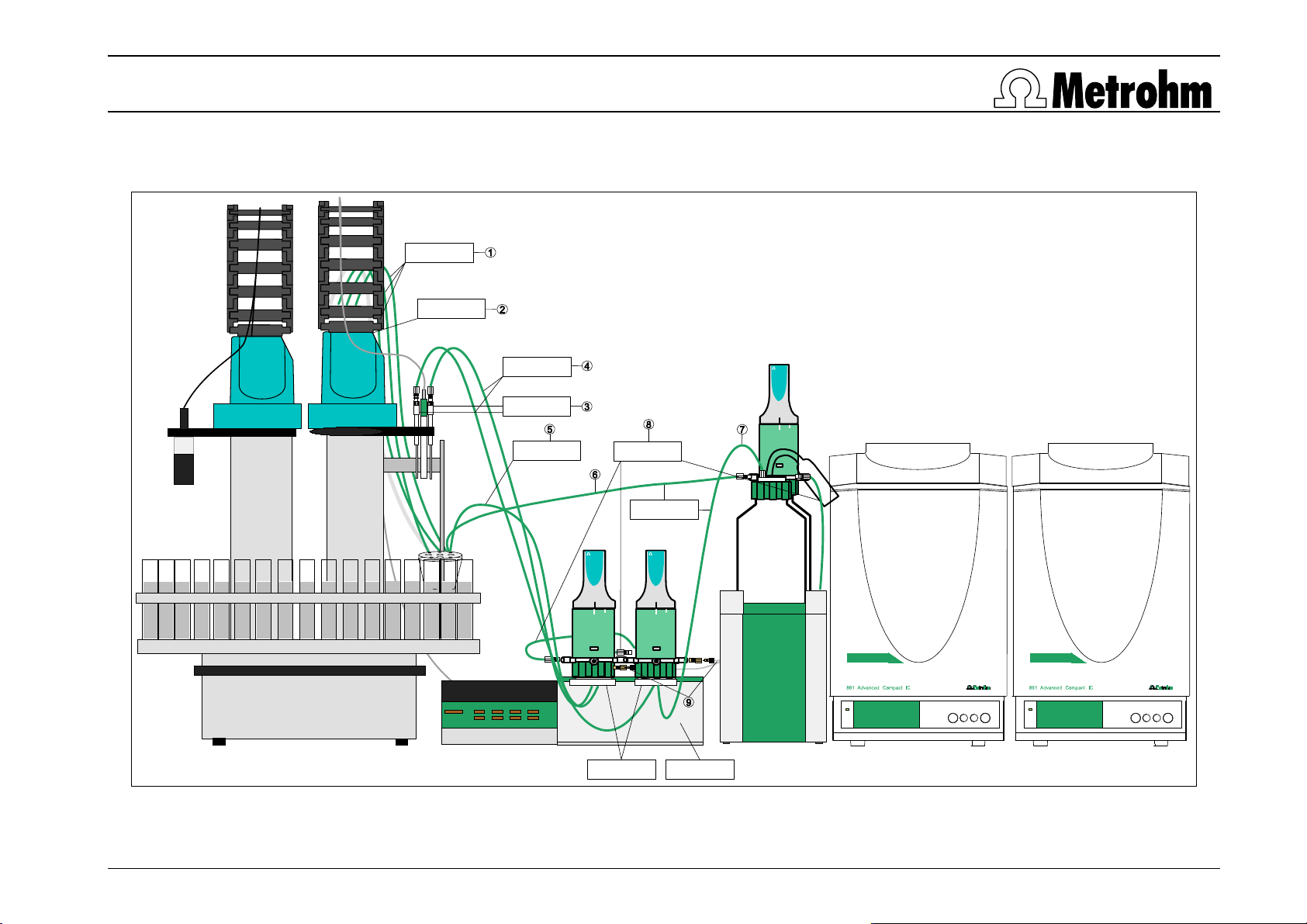
4.3 Overview of all the tubing connections
6.1805.060
6.1805.510
800 Dosino
20
Metrohm
mL
VENT
6.1805.110
6.1543.080
6.1805.060
6.1805.030
6.1805.100
800 Dosino
10
Metrohm
VENT
HNO
3
mL
Metrohm
800 Dosino
50
VENT
mL
6.2055.1006.1618.020
Overview of the tubing connections in the TitrIC 3 System
Page 10

Application Bulletin 287 e
Installation Instructions of TitrIC 3
Page 10/16
The three 60 cm FEP tubing connections (6.1850.060, supplied with 815) are used to connect
membrane pump 1 / tower 1 of the 815 and the three rinsing nozzles (6.2740.020, supplied with
815) to openings 2, 5 and 7 of the external cell (see page 7 and 11, chapter 5.1).
The 60 cm M8 PTFE tubing connection (6.1805.510) is used to connect membrane pump 1 / tower
2 of the 815 and the M8 PTFE aspiration tip (6.1543.170) to opening 1 of the external cell (see
page 7 and 11, chapter 5.1).
The two buret tips (6.1543.080) are each attached by a stopper (6.2730.030) to the titration head
(6.1462.070).
The two 80 cm FEP tubing connections (6.1850.110) are used to connect the buret tips
(6.1543.200) at the titration head (6.1462.070) and port 2 of the 10 mL and 50 mL Dosing Units.
The 60 cm FEP tubing connection (6.1850.060) is used to connect port 4 of 50 mL Dosing Unit and
opening 9 of the external cell (see page 7).
The 40 cm FEP tubing connection (6.1850.100, supplied with 807) is used to connect port 4 of the
10 mL Dosing Unit and the M6 opening of the eluent bottle attachment (6.1602.160); the FEP
aspiration tubing (6.1829.010, supplied with 807) should previously have been inserted. The
absorber tube (6.1609.000) is filled as usual with lime and cotton wool and inserted into the
opening provided for it in the eluent bottle attachment in order to protect the nitric acid from CO
.
2
The 40 cm FEP tubing connection (6.1850.100, supplied with 807) is used to connect port 1 of the
20 mL Dosing Unit and the buret tip in opening 3 of the external cell (see page 7).
The three 150 cm FEP tubing connections (6.1805.030) are connected to port 1 of the 10 mL and
the 50 mL Dosing Units, as well as port 3 of the 20 mL Dosing Unit; all three tubing connections
are then connected to the 10 L PE waste canister (6.1621.000).
Suitable lengths of the 0.97 mm PTFE capillary (6.1803.020, supplied with 861) are used to
connect port 3 of the 10 mL and the 50 mL Dosing Units (using the screws 6.2744.080 and
6.2744.070) and the injection valves of the two 861 Advanced Compact IC (position 1). The 10 mL
Dosing Unit must be connected to the 861 Advanced Compact IC for cations (2.861.0010) and the
50 mL Dosing Unit to the 861 Advanced Compact IC for anions (2.861.0020).
Page 11

Application Bulletin 287 e
Installation Instructions of TitrIC 3
Page 11/16
5 Miscellaneous
5.1 Membrane Pumps of 815
The membrane pump at tower 1 is used to deliver the DI water for rinsing of the external vessel, the
membrane pump at tower 2 to empty the external vessel.
Therefore dismount the Distributor Rinse/Aspirate of tower 1 and mount the new one (6.1808.170). This
enables to connect the lower part of membrane pump at tower 2 to the left connector of the Distributor
leading to the M8 aspiration tip to empty the external vessel. The upper part of the membrane pump is
connected to the waste canister (see page 6).
The upper part of membrane pump at tower 1 is connected to the right connector of the Distributor
leading to the three M6 rinsing nozzles to rinse the external vessel. The lower part of the membrane
pump is connected to the DI-water canister.
5.2 Stirrer
The 802 Rod Stirrer is inserted through opening 8 of the external cell and connected to the tower 1 of
the 815. The propeller (6.1909020) is pushed on from below.
5.3 Length of the aspiration tips in the external cell
Clamp the titration vessel to the titration vessel lid.
The M8 aspiration tip in opening 1 must reach right to the base of the titration vessel as this is
the only way to ensure that the external cell is cleaned properly.
The buret tips in openings 3 and 4 should reach the middle of the titration vessel.
5.4 Electrodes
The pH electrode (Aquatrode Plus with Pt 1000; 6.0257.000) is inserted into opening 9 together
with the SGJ sleeve (6.1236.050). The cable is connected to the 815 Robotic Sample
Processor at the rear top right. The plug of the gray cable is connected to the opening marked
Ind.. The red plugs with the adapters 6.2103.140 and 6.2103.130 (supplied with 809) are
inserted in the openings marked
If the electrode is not to be used for some time then it should be returned to its holder and kept
in the storage solution (6.2323.000).
Conductivity cell (6.0912.110): The measuring cell cable is led through the guide chain of the
815 and the two black plugs are inserted into the openings marked
Conductometer, the two red plugs into those marked Pt 100/1000. Later (as soon as the titration
head has been mounted) the measuring cell with the SGJ sleeve (6.1236.050) will be inserted
in the SGJ 14 opening of the titration head.
Temp.
Cond. Cell of 712
Page 12

Application Bulletin 287 e
Installation Instructions of TitrIC 3
Page 12/16
6 Software
6.1 Installation of the software
Edgeport driver – installation (Inside Out NETWORKS-CD): Connect the Edgeport with the
USB cable (included in 2.145.0320) with the PC and then insert the CD. It’s not necessary to
start windows update, click on
tiamo 1.1 – installation (tiamo-CD): All the standard directories proposed by the program should
be accepted.
IC Net 2.3 – installation (Metrodata-CD): All the standard directories proposed by the program
should be accepted. Restart windows.
TitrIC 1.0 – installation (Metrodata-CD): TitrIC 1.0 must only be installed after tiamo 1.1 and
IC Net 2.3 have already been installed. After installation the standard TitrIC directory can be
found under
C:\Programme\ Metrohm\TitrIC, the TitrIC.exe file under C:\Programme\Metrohm\tiamo\bin.
All programs must be shut down!
6.2 Configuration of tiamo
The Controller cable (6.2151.000), which is already connected to the 815, is now connected to an
USB interface on the PC. Wait a few seconds. The driver installation for 809 and 815 follows. It’s not
necessary to start windows update, click on
automatic installation of the software.
automatic installation of the software for both.
Switch on the 712 Conductometer
tiamo 1.1 is started
6.2.1 Devices
Connected devices are automatically recognized when tiamo is started. After confirmation of the automatically generated request the devices are stored in the configuration, keep the proposed device
names. The 712 Conductometer is not recognized automatically and must therefore be added with the
name
712_1 via Configuration / Devices / Edit / New / Meter / 712 Conductometer, as well as selected COM 5 under
the entry
to a different COM port. This is checked by clicking on
manager / Connections (COM and LPT)
RS 232 and confirmed with <OK>. Depending on the PC, the Edgeport port 1 could be assigned
Start / System control / System / Hardware / Device
and checking which COM port has been assigned to port 1 of the
Edgeport.
6.2.2 Swing Head configuration
Under Configuration at the top left, double-click on 815_1 under Devices, click on the entry Tower 1 and
afterwards on
Head
click on Configuration and Yes and then enter the following values:
Tower 2, set the Axial distance to 196.0 mm and in the middle of the window under Swing
Configuration of the Swing Head at tower 1 Configuration of the Swing Head at tower 2
Confirm the entries twice with <
OK> and then mark 815_1 under Devices and click on Edit / Initialize. Wait a
few seconds. The titration arm (6.1462.070) is now mounted onto the Swing Head at tower 1, the DISCOVER arm (6.1462.080) onto the Swing Head at tower 2 and is connected to
Ext. Pump 2 of tower 2.
Page 13

Application Bulletin 287 e
Installation Instructions of TitrIC 3
Page 13/16
6.2.3 Special beaker definition
Under Configuration mark 815_1, select Edit / Properties / Rack / Rack data / Special beaker, Special beaker 1, click
on Edit and define the position to be used for rinsing as Rack position. The last position is normally used
as the rinsing position. A sample vessel containing DI water should always stand in this position.
Confirm by clicking on
<OK> twice.
6.2.4 Lift positions
Under Configuration / Tools / Manual operation click on 815 Sample Changer / Tower 1 in the left-hand column
and use the entries Move and Assign position (See 815 Instructions for Use, chapter 2.4.6, page 47) to
define suitable values (click on <Assign> each time) for:
Shift position for changing the rack position (approx. 53 mm)
Work position for aspirating of the sample (approx. 173 mm)
Special position for dipping for the conductivity measurement (approx. 130 mm)
For the special position you must define the work position again, then at the right beside
click on
Tower and select Special position 1.
Work position
Please repeat these steps to define the settings for tower 2.
6.2.5 Solutions
The solutions to be used must, as usual, be defined in tiamo. Connect the Dosino of the 50 mL Dosing
unit to MSB 1 of the 809, the Dosino of the 10 mL Dosing unit to MSB 2 and the Dosino of the 20 mL
Dosing unit to MSB 3. The user is automatically requested to save the solutions – click on
order to ensure compatibility with the methods provided, they must be named as described below.
At the left click on
appropriate (empty) entries and enter the following under
Configuration, then at the top right under Titrants/Solutions double-click on the
Solution name and Concentration:
Configuration table for titrants/solutions
Now the tubing lengths and ports are defined for each Dosing unit under
Edit/Properties…/ Dosing unit as
follows:
<Yes>. In
anion cation HCl
Dosing Port
Prep/Empty
Dosing Port 1 Port 4 60 cm Port 1 60 cm Port 1 40 cm
Dosing Port 2 Port 3 0 cm Port 3 0 cm Port 3 0 cm
Fill Port Port 2 80 cm Port 2 80 cm Port 2 25 cm
Special Port Port 1 0 cm Port 4 40 cm Port 4 0 cm
Port Length Port Length Port Length
Special Port - Dosing Port 1 - Dosing Port 1 -
Configuration table of the three dosing units
Page 14

Application Bulletin 287 e
Installation Instructions of TitrIC 3
Page 14/16
6.2.6 Electrodes
pH electrode: Under Configuration/Sensors click on Edit/New/pH electrode and enter under Sensor
name Aquatrode Plus
<Ok>.
, type in the desired sensor information (e.g. serial number) and click on
Conductivity sensor: Under
Sensor name Conductivity sensor type in the desired sensor information and click on <Ok>.
Configuration/Sensors click on Edit/New/other sensor and enter under
6.2.7 Methods
The following seven methods are provided:
TitrIC 3 - complete run: With this method all the parameters possible with the standard instruments
are measured and the IC measurement is initiated.
TitrIC 3 - titration and measurement: Only titration and direct measurements are carried out; the IC
measurements are not initiated. In TitrIC under Settings/IC Net settings the IC Anions and IC Cations
have to be deactivated, or the method is started up only from tiamo.
TitrIC 3 - preparation of titration equipment: Th is method is used for preparing all titration instruments,
i.e., rinsing the tubing connections of the Dosing Units with reagents or deionized water and
rinsing the external cell. Start this method only from tiamo – not from TitrIC!
TitrIC 3 - IC calibration - anion & cation: This method is used for calibrating the IC measurements
with standard solutions without having to carry out the titration part of a typical TitrIC
measurement; this means that a lot of solution can be saved.
TitrIC 3 – semi automated pH calibration: With this method the pH electrode is calibrated automated;
the buffer solutions are poored into the titration vessel. Start this method only from tiamo – not
from TitrIC!
TitrIC 3 - pH calibration: Here the Aquatrode is taken out of the titration vessel and placed into the
buffer solutions. Start this method only from tiamo!
TitrIC 3 - titer determination: This method is used for the titer determination. Start this method only
from tiamo!
An automated conductivity cell calibration method for tiamo can be delivered if desired
(titric@metrohm.com); it is recommend to do it manually.
Import: Click on
directory
C:\Program Files\Metrohm\tiamo\methods_titric all methods and click on <Open>.
Method at the left, then select under File / Method manager… / Edit / Import… in the
Note!
Alterations of these methods should only be carried out by a person at the Administrator level
and who is thoroughly familiar with tiamo. Never forget that in TitrIC this new method must be
selected in the sample table under Methods tiamo.
Page 15
Application Bulletin 287 e
Installation Instructions of TitrIC 3
Page 15/16
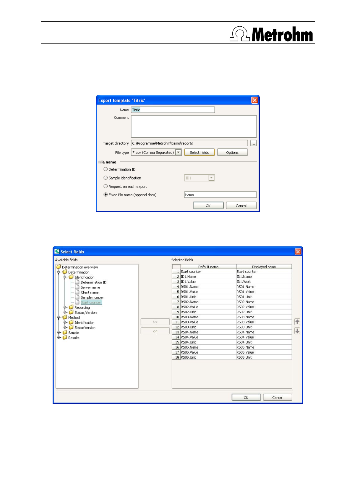
6.2.8 Configuration of the export template
Export template: tiamo must transfer its results to TitrIC in a particular way, which means that the
export template must be generated exactly in the following form:
Under
Database / Tools / Templates / Export templates / New enter the following:
Configuration of the export template in TitrIC
then click on Select fields and enter the following:
Input window for the export template
The entry
Start counter is obtained at the left by clicking on Determination/Identification, ID1.Name and ID1.value
are obtained at the left by clicking on Sample / Identifications, RS0x by clicking on Results / RS0xxx. By
clicking on the upper double arrow in the center the entries can be moved to the right. Of course
another number of results than five is possible.
Shut down tiamo 1.1 !
Page 16

Application Bulletin 287 e
Installation Instructions of TitrIC 3
Page 16/16
6.3 Configuration of IC Net
Start IC Net 2.3
Under
to save
Options / Global Preferences the following must be marked: under If method changed - Don’t ask
and System file overwrite - Always.
With the TitrIC software predefined IC systems are also installed. These are found under
C:\Program Files\Metrohm\IC Net 2.3\IC Net\Systems\Anion\anion.smt and C:\Program Files\Metrohm\IC Net
2.3\IC Net\Systems\Cation\cation.smt
. Open the two systems, click on Control / Connect to workplace
and choose the right COM-Port. If you don’t know to which COM-Ports the systems are
connected to you have to try out until you have communication between PC and the 861. Work
should always be carried out with these systems, as otherwise the result transfer to TitrIC will
be disturbed. This is why, if the systems have to be altered, the existing system is always
altered and saved under the same name.
The suppressor step is not made at the start of the measurement in the usual way, but with Fill
directly after the end of the chromatogram. These means that after long pauses between
measurements the suppression may no longer function. This is why after longer pauses you
should carry out a suppressor step manually and ensure that the injection valve is in the Fill
position.
Depending on the application and column it may be necessary to adapt the time program in the
IC system: Inject should always be carried out right at the start (0.10 min) of the time program,
Fill right at the end. In this way you can start to measure with a stable baseline immediately
after the sample loop has been filled by the Dosinos.
If a calibration is carried out later and the new calibration data are to be applied to a sample that
has already been measured then this is possible by using TitrIC – see the online help of the
TitrIC software under
Database / Recalculate / Recalculate for the results of several samples.
Shut down IC Net 2.3
6.4 Configuration of TitrIC
TitrIC is started (tiamo and IC Net are started automatically at the s am e time)
All paths have already been entered as defaults and the system is ready for work. If other paths
have been used instead of the default paths then this must be altered in the corresponding
dialog under
Workplace / Settings / ….
TitrIC starts tiamo and IC Net at the same time. However, the tiamo window is not visible, but
can be brought to the foreground in TitrIC via
View / Show tiamo.
If TitrIC is shut down then tiamo will also be shut down automatically – but IC Net must always
be shut down individually. Always shut down TitrIC as the first program! If tiamo is accidentally
shut down first then TitrIC is also no longer visible; the program will continue to run in the
background. It can then be shut down with a right-hand click on an empty position in the
and a left-hand click on
For further information please consult the TitrIC online help (
Task manager / Processes / TitrIC.exe / End process.
? / Show Help) or contact the
responsible person at your local Metrohm agency. You can also report your problems to the
following support email: titric@metrohm.com.
Always start and shut down TitrIC first!
Taskbar
 Loading...