

Page 1
É2425848800gËÍ
2425848800
B-Class Electric Drive
Operator's Manual
Order no. P242 0017 13 Part no. 242 584 88 00 Edition A 2017
B-Class Electric Drive Operator's Manual
Page 2

Symbols
In this Operator's Manual you will find the following symbols:
WARNING
G
Warning notes make you aware of dangers
which could pose a threat to your health or
life, or to the health and life of others.
Environmental note
H
Environmental notes provide you with information on environmentally aware actions or
disposal.
Notes on material damage alert you to dan-
!
gers that could lead to damage to your vehicle.
Practical tips or further information that
i
could be helpful to you.
X
X
(Y
page)
Dis‐Dis‐
playplay
This symbol indicates an instruction
that must be followed.
Several of these symbols in succession
indicate an instruction with several
steps.
This symbol tells you where you can
find more information about a topic.
This text indicates a message on the
multifunction display/multimedia display.
Publication details
Internet
Further information about Mercedes-Benz vehicles and about Daimler AG can be found on the
following websites:
http://www.mbusa.com
Editorial office
©
Daimler AG: not to be reprinted, translated or
otherwise reproduced, in whole or in part, without written permission from Daimler AG.
Vehicle manufacturer
Daimler AG
Mercedesstraße 137
70327 Stuttgart
Germany
As at 14.10.2015
Page 3
Welcome to the world of Mercedes-Benz
We urge you to read this Operator's Manual
carefully and familiarize yourself with the vehicle before driving. For your own safety and a
longer vehicle life, follow the instructions and
warning notices in this Operator's Manual.
Ignoring them could result in damage to the
vehicle or personal injury to you or others.
Vehicle damage caused by failure to follow
instructions is not covered by the MercedesBenz Limited Warranty.
The equipment or product designation of your
vehicle may vary depending on:
R
Model
R
Order
R
Country specification
R
Availability
Mercedes-Benz therefore reserves the right to
introduce changes in the following areas:
R
Design
R
Equipment
R
Technical features
The equipment in your vehicle may therefore
differ from that shown in the descriptions and
illustrations.
The following are integral components of the
vehicle:
R
Printed Operator's Manual
R
Maintenance Booklet
R
Equipment-dependent supplements
Keep these documents in the vehicle at all
times. If you sell the vehicle, always pass all
documents on to the new owner.
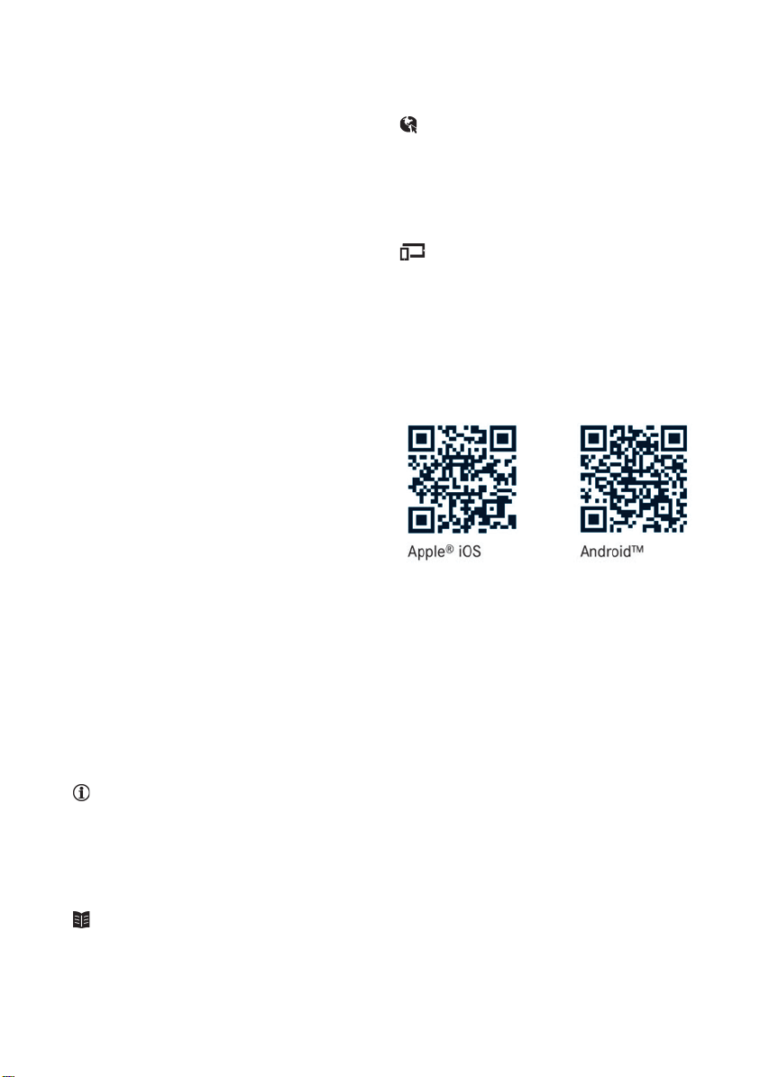
You can also use the Mercedes-Benz Guides
App:
Your Operator's Manual:
Digital form inside the vehicle
The Digital Operator's Manual provides
comprehensive and specifically adapted
information on your vehicle's equipment
and multimedia system. It contains informative animations, individual language
settings and an intuitive search function.
Booklet inside the vehicle
In addition to this manual and the aforementioned digital media, you also have the
option to obtain a comprehensive printed
version of the Supplement for your multi-
media system from your authorized
Mercedes-Benz Center.
Digital form via the Internet
The Operator's Manual on the Internet provides easy access to all information
regarding your vehicle and multimedia system. It also provides helpful animations,
interesting background information and a
wide array of search options.
Digital form as an App
Using the Mercedes-Benz Guides App, you
can view all the information on your vehicle
and multimedia system via mobile Internet
or download it independently of network
access. Available for smartphones or tablets.
You can also use the Mercedes-Benz Guides
App:
Please note that the Mercedes-Benz Guides App
may not yet be available in your country.
Mercedes-Benz USA, LLC
Mercedes-Benz Canada, Inc.
A Daimler Company
2425848800
É2425848800gËÍ
Page 4

2
Contents
Index ....................................................... 4
Digital Operator's Manual .................. 21
Introduction ...........................................21
Operation ............................................... 21
Introduction ......................................... 22
Protecting the environment ...................22
Genuine Mercedes-Benz parts ...............22
Operator's Manual ................................. 23
Service and vehicle operation ................23
Operating safety .................................... 24
QR codes for the rescue card ................28
Data stored in the vehicle ...................... 28
Information on copyright ....................... 29
At a glance ........................................... 31
Cockpit .................................................. 31
Instrument cluster ................................. 32
Multifunction steering wheel ................. 33
Center console ...................................... 34
Door control panel ................................. 36
Overhead control panel .........................37
Safety ................................................... 38
Panic alarm ............................................ 38
Occupant safety .................................... 38
Children in the vehicle ........................... 52
Pets in the vehicle ................................. 58
Driving safety systems ........................... 58
Protection against theft .........................64
Opening and closing ........................... 66
SmartKey ............................................... 66
Doors ..................................................... 72
Cargo compartment ...............................74
Side windows ......................................... 75
Seats, steering wheel and mirrors .... 79
Correct driver's seat position ................ 79
Seats ..................................................... 79
Steering wheel ....................................... 83
Mirrors ................................................... 83
Memory function ................................... 85
Lights and windshield wipers ............ 87
Exterior lighting ..................................... 87
Interior lighting ...................................... 89
Replacing bulbs ..................................... 90
Windshield wipers .................................. 95
Climate control .................................... 99
Overview of climate control systems ..... 99
Operating the climate control sys-
tems .................................................... 100
Air vents .............................................. 106
Driving and parking .......................... 108
Notes on breaking-in a new vehicle ..... 108
Driving ................................................. 108
Transmission ....................................... 111
High-voltage battery ............................ 117
Parking ................................................ 128
Driving tips .......................................... 131
Driving systems ................................... 136
On-board computer and displays .... 152
Important safety notes ........................ 152
Displays and operation ........................ 152
Menus and submenus ......................... 156
Display messages ................................ 167
Warning and indicator lamps in the
instrument cluster ............................... 190
Multimedia system ........................... 201
General notes ...................................... 201
Important safety notes ........................ 201
Function restrictions ............................ 201
Operating system ................................ 202
Stowage and features ...................... 207
Loading guidelines ............................... 207
Stowage areas ..................................... 207
Features .............................................. 216
Maintenance and care ...................... 231
Engine compartment ........................... 231
ASSYST PLUS ...................................... 233
Care ..................................................... 234
Page 5

Breakdown assistance ..................... 241
Where will I find...? .............................. 241
Flat tire ................................................ 241
Batteries .............................................. 246
Jump-starting ....................................... 249
Towing ................................................. 251
Fuses ................................................... 254
Wheels and tires ............................... 257
Important safety notes ........................ 257
Operation ............................................ 257
Winter operation .................................. 259
Tire pressure ....................................... 260
Loading the vehicle .............................. 266
All about wheels and tires ................... 269
Changing a wheel ................................ 275
Wheel and tire combinations ............... 279
Technical data ................................... 281
Information regarding technical data ... 281
Vehicle electronics .............................. 281
Identification plates ............................. 282
Service products and filling capaci-
ties ...................................................... 283
Vehicle data ......................................... 286
Contents
3
Page 6

Index
4
1, 2, 3 ...
12 V socket
see Sockets
A
ABS (Anti-lock Braking System)
Display message ............................ 168
Function/notes ................................ 59
Important safety notes .................... 59
Warning lamp .................................193
Accident
Automatic measures after an acci-
dent ................................................. 52
Activating media mode
General notes ................................ 206
Activating/deactivating cooling
with air dehumidification ................. 100
Active Brake Assist
Activating or deactivating .............. 162
Display message ............................ 174
Function/notes ................................ 60
ADAPTIVE BRAKE ................................. 64
Additional speedometer ................... 165
Address book
see also Digital Operator's Man-
ual ..................................................201
Adjusting the volume
Audio 20 ........................................ 202
COMAND ....................................... 202
Air bags
Deployment ..................................... 50
Display message ............................ 176
Front air bag (driver, front
passenger) ....................................... 44
Important safety notes .................... 43
Introduction ..................................... 43
Knee bag .......................................... 44
Occupant Classification System
(OCS) ............................................... 45
PASSENGER AIR BAG indicator
lamps ............................................... 39
Side impact air bag .......................... 45
Window curtain air bag .................... 45
Air vents
Important safety notes .................. 106
Rear ............................................... 106
Setting the center air vents ........... 106
Setting the side air vents ...............106
Air-conditioning system
see Climate control
Alarm
ATA (Anti-Theft Alarm system) ......... 65
Switching off (ATA) .......................... 65
Switching the function on/off
(ATA) ................................................ 65
Alarm system
see ATA (Anti-Theft Alarm system)
Antenna ................................................ 26
Anti-lock braking system
see ABS (Anti-lock Braking System)
Anti-Theft Alarm system
see ATA (Anti-Theft Alarm system)
Ashtray ............................................... 217
Assistance display (on-board com-
puter) ..................................................162
Assistance menu (on-board com-
puter) ..................................................162
ASSYST PLUS
Displaying a service message ........233
Driving abroad ............................... 234
Hiding a service message .............. 233
Information about Service ............. 234
Resetting the service interval dis-
play ................................................ 234
Service message ............................ 233
Special service requirements ......... 234
ATA (Anti-Theft Alarm system)
Activating/deactivating ................... 65
Function ........................................... 65
Switching off the alarm .................... 65
ATTENTION ASSIST
Activating/deactivating ................. 163
Display message ............................ 182
Function/notes ............................. 148
Audio 20
Switching on/off ........................... 202
Audio menu (on-board computer) .... 160
Audio system
see separate operating instructions
Authorized Mercedes-Benz Center
see Qualified specialist workshop
Authorized workshop
see Qualified specialist workshop
Page 7

Index
5
AUTO lights
Display message ............................ 180
see Lights
Automatic car wash (care) ...............234
Automatic headlamp mode ................ 87
Automatic transmission
Display message ............................ 186
B
Back button ....................................... 202
Backup lamp
Display message ............................ 179
Replacing bulbs ............................... 93
Bag hook ............................................ 212
BAS (Brake Assist System) ................. 59
Battery (SmartKey)
Checking .......................................... 69
Important safety notes .................... 68
Replacing ......................................... 69
Battery (vehicle)
Charging ........................................ 248
Display message ............................ 181
Important safety notes .................. 246
Jump starting ................................. 249
Belt
see Seat belts
Blind Spot Assist
Activating/deactivating (on-
board computer) ............................ 163
Display message ............................ 183
Notes/function .............................. 150
Blootooth
®
Connecting a different mobile
phone ............................................ 206
Bluetooth
®
Searching for a mobile phone ........205
see also Digital Operator's Man-
ual ..................................................201
Telephony ...................................... 204
Brake Assist
see BAS (Brake Assist System)
Brake fluid
Display message ............................ 173
Notes ............................................. 284
Brake force distribution
see EBD (electronic brake force
distribution)
Brake lamps
Display message ............................ 178
Brake system
Driving safety systems ..................... 64
Brakes
ABS ..................................................59
BAS .................................................. 59
Brake fluid (notes) ......................... 284
Braking assistance appropriate to
the situation ..................................... 61
Display message ............................ 168
EBD .................................................. 63
Hill start assist ............................... 111
HOLD function ............................... 138
Important safety notes .................. 133
Maintenance .................................. 134
Parking brake ................................ 130
Riding tips ...................................... 133
Warning lamp ................................. 192
Braking assistance appropriate to
the situation
Function/notes ................................ 61
Breakdown
Towing away .................................. 251
Where will I find...? ........................ 241
see Flat tire
Buttons on the steering wheel ......... 154
C
California
Important notice for retail cus-
tomers and lessees .......................... 23
Calling up a malfunction
see Display messages
Car
see Vehicle
Care
Car wash ........................................ 234
Carpets .......................................... 240
Display ........................................... 238
Exterior lights ................................ 237
Gear or selector lever .................... 239
Interior ........................................... 238
Matte finish ................................... 236
Notes ............................................. 234
Paint .............................................. 235
Plastic trim .................................... 238
Page 8

Index
6
Power washer ................................ 235
Rear view camera .......................... 238
Roof lining ...................................... 240
Seat belt ........................................239
Seat cover ..................................... 239
Sensors ......................................... 237
Steering wheel ............................... 239
Trim pieces ....................................239
Washing by hand ........................... 235
Wheels ...........................................236
Windows ........................................ 236
Wiper blades .................................. 237
Wooden trim .................................. 239
Cargo compartment cover
Important safety notes .................. 212
Installing/removing ....................... 213
Notes/how to use ......................... 212
Cargo compartment enlargement ... 211
Cargo compartment floor
Height adjustment ......................... 215
Important safety notes .................. 214
Opening/closing ............................ 214
Stowage well (under) ..................... 214
Cargo net
Attaching ....................................... 213
Important safety information ......... 213
Cargo tie down rings ......................... 212
CD
see also Digital Operator's Man-
ual ..................................................201
CD player (on-board computer) ........160
Center console
Lower section .................................. 35
Upper section .................................. 34
Central locking
Automatic locking (on-board com-
puter) ............................................. 166
Locking/unlocking (SmartKey) ........66
Change of address .............................. 24
Change of ownership .......................... 24
Changing the bulb
Cornering light function ...................93
Charge level display .......................... 153
Charging
with RANGE PLUS .......................... 164
see Charging the high-voltage battery
Charging cable
Connecting .................................... 124
Controls .........................................123
Important safety notes .................. 122
Removing ....................................... 125
Storing ...........................................122
Warming up ................................... 118
Charging the high-voltage battery
(important safety notes) ................... 117
Child
Restraint system .............................. 54
Child seat
Forward-facing restraint system ...... 57
LATCH-type (ISOFIX) child seat
anchors ............................................ 55
On the front-passenger seat ............ 56
Rearward-facing restraint system .... 56
Top Tether ....................................... 55
Child-proof locks
Important safety notes .................... 57
Rear doors ....................................... 58
Children
Special seat belt retractor ............... 53
Cigarette lighter ................................ 218
Cleaning
Mirror turn signal ........................... 237
Climate control
Automatic climate control (dual-
zone) ................................................ 99
Auxiliary climate control (on-
board computer) ............................ 164
Controlling automatically ............... 101
Convenience opening/closing
(air-recirculation mode) ................. 104
Cooling with air dehumidification .. 100
Defrosting the windows ................. 103
Defrosting the windshield .............. 102
General notes .................................. 99
Immediate pre-entry climate con-
trol ................................................. 105
Indicator lamp ................................ 101
Information about using auto-
matic climate control ..................... 100
Maximum cooling .......................... 103
Overview of systems ........................ 99
Pre-entry climate control at
departure time ............................... 105
Page 9

Index
7
Pre-entry climate control at time
of departure (on-board computer)..164
Pre-entry climate control via key ... 105
Pre-entry climate control via key
(on-board computer) ......................164
Problem with the rear window
defroster ........................................ 103
Problems with cooling with air
dehumidification ............................ 101
Refrigerant ..................................... 285
Refrigerant filling capacity ............. 286
Setting the air distribution ............. 102
Setting the air vents ......................106
Setting the airflow ......................... 102
Setting the temperature ................ 101
Switching air-recirculation mode
on/off ............................................ 104
Switching on/off ........................... 100
Switching the rear window
defroster on/off ............................ 103
Switching the ZONE function
on/off ............................................ 102
Cockpit
Overview .......................................... 31
COMAND
Generated electricity ..................... 120
Switching on/off ........................... 202
COMAND display
Cleaning ......................................... 238
Combination switch ............................ 88
Compass
Calibrating ..................................... 229
Calling up ....................................... 228
Magnetic field zone maps .............. 229
Setting ...........................................229
Connecting a USB device
see also Digital Operator's Man-
ual ..................................................201
Consumption statistics (on-board
computer) .......................................... 156
Controller ...........................................202
Convenience closing feature .............. 77
Convenience opening feature ............ 76
Convenience opening/closing (air-
recirculation mode) ........................... 104
Coolant (engine)
Checking the level ......................... 232
Filling capacity ............................... 285
Important safety notes .................. 284
Cooling
see Climate control
Copyright ............................................. 29
Cornering light function
Changing the bulb ............................ 93
Display message ............................ 178
Function/notes ................................ 89
Cruise control
Activation conditions ..................... 137
Cruise control lever ....................... 136
Deactivating ................................... 137
Display message ............................ 184
Driving system ............................... 136
Function/notes .............................136
Important safety notes .................. 136
Setting a speed .............................. 137
Storing and maintaining current
speed ............................................. 137
Cup holder
Center console .............................. 216
Important safety notes .................. 216
Rear compartment ......................... 217
Customer Assistance Center
(CAC) ..................................................... 27
Customer Relations Department ....... 27
D
Data
see Technical data
Daytime running lamps
Display message ............................ 180
Function/notes ................................ 87
Switching on/off (on-board com-
puter) ............................................. 166
Declarations of conformity ................. 26
Departure time
Setting (on-board computer) .......... 163
Diagnostics connection ......................26
Digital Operator's Manual
Help .................................................21
Introduction .....................................21
Digital speedometer .........................158
DIRECT SELECT lever
Transmission ................................. 112
Page 10

Index
8
Display
High-voltage battery charge level
(instrument cluster) .......................153
Display messages
ASSYST PLUS ................................ 233
Calling up (on-board computer) ..... 167
Drive system .................................. 181
Driving systems .............................182
General notes ................................ 167
Hiding (on-board computer) ........... 167
Lights ............................................. 178
Safety systems .............................. 168
SmartKey ....................................... 189
Tires ............................................... 185
Vehicle ...........................................186
Displaying electrical consumption
(on-board computer) ......................... 158
Displaying energy consumption
(on-board computer) ......................... 158
Distance recorder .............................156
Distance warning (warning lamp) .... 199
Distance warning function
Function/notes ................................ 60
Warning lamp ................................. 199
Doors
Automatic locking (on-board com-
puter) ............................................. 166
Automatic locking (switch) ...............73
Central locking/unlocking
(SmartKey) .......................................66
Control panel ...................................36
Display message ............................ 187
Emergency locking ........................... 73
Emergency unlocking ....................... 73
Important safety notes .................... 72
Opening (from inside) ...................... 72
Drinking and driving ......................... 132
Drive system
Jump-starting ................................. 249
Starting with the SmartKey ............ 111
Starting with the Start/Stop but-
ton ................................................. 110
Switching off .................................. 129
Driver's door
see Doors
Driving abroad
Mercedes-Benz Service ................. 234
Driving on flooded roads .................. 135
Driving safety system
Active Brake Assist .......................... 60
Braking assistance appropriate to
the situation ..................................... 61
Driving safety systems
ABS (Anti-lock Braking System) ....... 59
ADAPTIVE BRAKE ............................. 64
BAS (Brake Assist System) .............. 59
Distance warning function ............... 60
EBD (electronic brake force distri-
bution) ............................................. 63
ESP®(Electronic Stability Pro-
gram) ............................................... 62
Important safety information ........... 58
Overview .......................................... 58
STEER CONTROL ............................. 64
Driving system
Parking assist PARKTRONIC .......... 139
Parking Pilot .................................. 142
Driving systems
ATTENTION ASSIST ........................ 148
Blind Spot Assist ............................ 150
Cruise control ................................ 136
Display message ............................ 182
HOLD function ............................... 138
Rear view camera .......................... 145
Driving tips
Brakes ........................................... 133
Break-in period .............................. 108
Checking brake lining thickness .... 134
Downhill gradient ........................... 133
Drinking and driving ....................... 132
Driving in winter ............................. 135
Driving on flooded roads ................ 135
Driving on wet roads ...................... 135
Energy ........................................... 132
General .......................................... 131
Hydroplaning ................................. 135
Icy road surfaces ........................... 135
Limited braking efficiency on sal-
ted roads ....................................... 134
Snow chains .................................. 259
Wet road surface ........................... 134
DVD video
Operating (on-board computer) ..... 160
see also Digital Operator's Man-
ual .................................................. 201
Page 11

Index
9
E
E‑CELL display ...................................152
EBD (electronic brake force distribution)
Display message ............................ 170
Function/notes ................................ 63
ECO display
Function/notes .............................132
On-board computer ....................... 156
Electric motor number ......................283
Electrical energy generated
(COMAND) .......................................... 120
Electronic Stability Program
see ESP®(Electronic Stability Program)
Emergency
Automatic measures after an acci-
dent ................................................. 52
Emergency release
Driver's door ....................................73
Vehicle .............................................73
Emergency Tensioning Devices
Activation .........................................50
Emergency unlocking
Tailgate ............................................ 75
Energy
Driving tips .................................... 132
Energy flow display ........................... 157
Entering an address
see also Digital Operator's Man-
ual .................................................. 201
ESP®(Electronic Stability Program)
Activating/deactivating (on-
board computer) ............................ 162
Characteristics ................................. 63
Deactivating/activating (notes) ....... 63
Display message ............................ 168
Function/notes ................................ 62
General notes .................................. 62
Important safety information ........... 62
Warning lamp ................................. 195
ETS/4ETS (Electronic Traction Sys-
tem) ...................................................... 62
Exhaustive discharging (high-volt-
age battery) ....................................... 248
Exterior lighting
Cleaning ......................................... 237
see Lights
Exterior mirrors
Adjusting ......................................... 84
Dipping (automatic) ......................... 84
Out of position (troubleshooting) ..... 84
Storing settings (memory func-
tion) ................................................. 86
Storing the parking position ............. 85
Eyeglasses compartment ................. 208
F
Favorites
Overview ........................................ 203
Flat tire
MOExtended tires .......................... 242
Preparing the vehicle ..................... 241
TIREFIT kit ...................................... 243
Floormats ........................................... 229
Folding table ...................................... 209
Frequencies
Mobile phone ................................. 281
Two-way radio ................................ 281
Front-passenger seat
Folding the backrest forward/
back ............................................... 210
Fuel
Fuel gauge ....................................... 32
Fuses
Allocation chart ............................. 256
Before changing ............................. 255
Fuse box in the engine compart-
ment .............................................. 255
Fuse box in the front-passenger
footwell .......................................... 256
Important safety notes .................. 254
G
Garage door opener
Clearing the memory ..................... 228
General notes ................................ 226
Important safety notes .................. 226
Opening/closing the garage door..228
Problems when programming ........228
Programming (button in the rear-
view mirror) ................................... 226
Synchronizing the rolling code ....... 227
Page 12

10
Index
Generated electrical energy (Audio
20) ...................................................... 120
Genuine parts ...................................... 22
Glove box ........................................... 208
Google™ Local Search
see also Digital Operator's Man-
ual .................................................. 201
H
Handbrake
see Parking brake
Hazard warning lamps
Display message ............................ 188
Switching on/off .............................. 89
Head restraints
Adjusting ......................................... 80
Adjusting (manually) ........................ 81
Adjusting (rear) ................................ 81
Headlamps
Fogging up ....................................... 89
see Automatic headlamp mode
Heating
see Climate control
High beam flasher ............................... 88
High-beam headlamps
Display message ............................ 179
Replacing bulbs ............................... 92
Switching on/off .............................. 88
High-voltage battery
Battery care ................................... 119
Charging (charging station) ............ 125
Charging (mains socket) ................ 122
Charging cable warming ................ 118
Cruise range .................................. 120
Discharged battery ........................ 119
Display message ............................ 181
Displaying energy consumption
(on-board computer) ...................... 158
Displaying the range (on-board
computer) ...................................... 158
Energy consumption ...................... 120
General notes ................................ 118
Method of operation ...................... 119
Outside temperatures .................... 119
Overvoltage protection .................. 118
Problems with the charging proc-
ess ................................................. 126
Reserve, warning lamp ................... 199
Terms of use .................................. 119
High-voltage disconnect device ......... 26
Hill start assist .................................. 111
HOLD function
Activating ....................................... 138
Deactivating ................................... 138
Display message ............................ 182
Function/notes ............................. 138
Home address
see also Digital Operator's Man-
ual .................................................. 201
Hood
Closing ........................................... 232
Display message ............................ 187
Important safety notes .................. 231
Opening ......................................... 231
Horn ...................................................... 31
Hydroplaning ..................................... 135
I
Ignition lock
see Key positions
Immobilizer .......................................... 64
Indicator lamps
see Warning and indicator lamps
Indicators
see Turn signals
Instrument cluster
Overview .......................................... 32
Power display ................................ 153
Settings ......................................... 165
Warning and indicator lamps ........... 32
Instrument cluster lighting .............. 152
Interior lighting
Control ............................................. 90
Overview .......................................... 89
Reading lamp ................................... 89
Internet connection
Via mobile service module ............. 128
®
iPod
see also Digital Operator's Man-
ual .................................................. 201
Page 13

Index
11
J
Jack
Storage location ............................241
Using ............................................. 277
K
Key positions
Start/Stop button .......................... 109
KEYLESS-GO
Convenience closing feature ............ 77
Deactivation ..................................... 66
Locking ............................................ 66
Unlocking ......................................... 66
Kickdown
Driving tips ....................................114
Knee bag .............................................. 44
L
Lamps
see Warning and indicator lamps
LATCH-type (ISOFIX) child seat
anchors ................................................ 55
License plate lamp
Changing bulbs ................................ 94
License plate lamp (display mes-
sage) ................................................... 179
Light function, active
Display message ............................ 180
Light sensor (display message) ....... 180
Lights
Automatic headlamp mode .............. 87
Cornering light function ................... 89
Fogged up headlamps ......................89
Hazard warning lamps ..................... 89
High beam flasher ............................ 88
High-beam headlamps ..................... 88
Light switch .....................................87
Low-beam headlamps ...................... 87
Parking lamps .................................. 88
Rear fog lamp .................................. 88
Setting exterior lighting ................... 87
Standing lamps ................................ 88
Switching the daytime running
lamps on/off (on-board com-
puter) ............................................. 166
Turn signals ..................................... 88
Loading guidelines ............................ 207
Locking
see Central locking
Locking (doors)
Automatic ........................................ 73
Emergency locking ........................... 73
From inside (central locking but-
ton) .................................................. 72
Locking centrally
see Central locking
Locking verification signal (on-
board computer) ............................... 166
Low-beam headlamps
Display message ............................ 178
Replacing bulbs ............................... 92
Switching on/off .............................. 87
Lumbar support
Adjusting the 4-way lumbar sup-
port .................................................. 81
M
M+S tires ............................................ 259
Malfunction message
see Display messages
Map (navigation)
Switching the range on the map
on/off ............................................ 121
Matte finish (cleaning instruc-
tions) .................................................. 236
Maximum charge current
Setting (charging cable) ................. 123
mbrace
Call priority .................................... 222
Display message ............................ 173
Downloading destinations
(COMAND) ..................................... 222
Downloading routes ....................... 225
Emergency call .............................. 220
General notes ................................ 219
Geo fencing ................................... 225
Locating a stolen vehicle ............... 224
MB info call button ........................ 221
Remote fault diagnosis .................. 224
Remote vehicle locking .................. 224
Roadside assistance button ........... 221
Search & Send ............................... 223
Self-test ......................................... 219
Page 14

12
Index
Speed alert .................................... 225
System .......................................... 219
Triggering the vehicle alarm ........... 226
Vehicle remote unlocking .............. 223
Mechanical key
Function/notes ................................ 68
Inserting .......................................... 68
Locking vehicle ................................ 73
Removing ......................................... 68
Unlocking the driver's door .............. 73
Memory card (audio) ......................... 160
Memory function ................................. 85
Message memory (on-board com-
puter) .................................................. 167
Messages
see Display messages
Mirror turn signal
Cleaning ......................................... 237
Mirrors
see Exterior mirrors
see Rear-view mirror
see Vanity mirror (in the sun visor)
Mobile phone
Connecting (Bluetooth®inter-
face) .............................................. 204
Connecting another mobile
phone ............................................ 206
Frequencies ................................... 281
Installation ..................................... 281
Menu (on-board computer) ............ 160
Transmission output (maximum) .... 281
Modifying the programming
(SmartKey) ........................................... 67
MOExtended tires .............................. 242
Mounting wheels
Lowering the vehicle ...................... 279
Mounting a new wheel ................... 278
Preparing the vehicle ..................... 276
Raising the vehicle ......................... 277
Removing a wheel .......................... 278
Securing the vehicle against roll-
ing away ........................................ 276
MP3
Operation ....................................... 160
see also Digital Operator's Man-
ual .................................................. 201
Multifunction display
Function/notes ............................. 155
Permanent display ......................... 165
Multifunction steering wheel
Operating the on-board computer..154
Overview .......................................... 33
Music files
see also Digital Operator's Man-
ual ..................................................201
N
Navigation
Entering a destination .................... 203
Menu (on-board computer) ............ 158
see also Digital Operator's Man-
ual ..................................................201
Notes on breaking-in a new vehi-
cle ....................................................... 108
O
Occupant Classification System
(OCS)
Conditions ....................................... 46
Faults ............................................... 49
Operation ......................................... 46
System self-test ............................... 48
Occupant safety
Air bags ...........................................43
Automatic measures after an acci-
dent ................................................. 52
Children in the vehicle ..................... 52
Important safety notes .................... 38
Introduction to the restraint sys-
tem .................................................. 38
Occupant Classification System
(OCS) ............................................... 45
PASSENGER AIR BAG indicator
lamps ............................................... 39
Pets in the vehicle ........................... 58
Restraint system warning lamp ........ 39
Seat belt .......................................... 40
OCS
Conditions ....................................... 46
Faults ............................................... 49
Operation ......................................... 46
System self-test ............................... 48
Odometer ........................................... 156
Page 15

Index
13
On-board computer
Assistance graphic menu ............... 162
Assistance menu ........................... 162
Audio menu ................................... 160
Display messages .......................... 167
Displaying a service message ........ 233
E‑CELL menu ................................. 163
Factory settings ............................. 166
Important safety notes .................. 152
Instrument cluster submenu ..........165
Lighting submenu .......................... 166
Menu overview .............................. 156
Message memory .......................... 167
Navigation menu ............................ 158
Operation ....................................... 154
Service menu ................................. 163
Settings menu ............................... 163
Standard display ............................ 156
Telephone menu ............................ 160
Trip menu ...................................... 156
Vehicle submenu ........................... 166
Video DVD operation ..................... 160
Online access .................................... 127
Operating safety
Declaration of conformity ................ 26
Important safety notes .................... 24
Operating system
see On-board computer
Operation
Digital Operator's Manual ................ 21
Operator's Manual
Vehicle equipment ........................... 23
Outside temperature display ........... 152
Overhead control panel ...................... 37
Override feature
Rear side windows ........................... 58
P
Paint code number ............................ 282
Paintwork (cleaning instructions) ... 235
Panic alarm .......................................... 38
Parking
Important safety notes .................. 128
Parking brake ................................ 130
Parking position for the exterior
mirror on the front-passenger
side .................................................. 85
Rear view camera .......................... 145
Parking aid
see Exterior mirrors
see Rear view camera
Parking Assist PARKTRONIC
Deactivating/activating ................. 141
Driving system ............................... 139
Function/notes ............................. 139
Important safety notes .................. 139
Problems (malfunctions) ................ 141
Sensor range ................................. 139
Warning display ............................. 140
Parking brake
Applying automatically ................... 130
Applying or releasing manually ...... 130
Display message ............................ 171
Electric parking brake .................... 130
Emergency braking ........................ 131
General notes ................................ 130
Releasing automatically ................. 131
Warning lamp ................................. 198
Parking lamps
Replacing bulbs ............................... 92
Switching on/off .............................. 88
Parking Pilot
Canceling ....................................... 145
Detecting parking spaces .............. 142
Display Message ............................ 183
Exiting a parking space .................. 144
Function/notes ............................. 142
Important safety notes .................. 142
Parking .......................................... 143
PASSENGER AIR BAG
Display message ............................ 176
Indicator lamps ................................ 39
Problem (malfunction) ................... 176
Pets in the vehicle ............................... 58
Phone book
see also Digital Operator's Man-
ual .................................................. 201
Plastic trim (cleaning instruc-
tions) .................................................. 238
Power display .................................... 153
Power washers .................................. 235
Power windows
see Side windows
Program selector button .................. 114
Page 16

14
Index
Protection against theft
ATA (Anti-Theft Alarm system) ......... 65
Immobilizer ...................................... 64
Protection of the environment
General notes ..................................22
Pulling away
General notes ................................ 111
Hill start assist ...............................111
Q
QR code
Mercedes-Benz Guide App ................. 1
Rescue card ..................................... 28
Qualified specialist workshop ........... 27
R
Radio
Selecting a station ......................... 160
see separate operating instructions
Radio mode
see also Digital Operator's Man-
ual ..................................................201
Radio-wave reception/transmission in the vehicle
Declaration of conformity ................ 26
Range
RANGE PLUS ................................. 120
RANGE PLUS
charge ...........................................164
Range ............................................ 120
Reading lamp ....................................... 89
READY indicator ................................ 152
Rear compartment
Setting the air vents ......................106
Rear fog lamp
Display message ............................ 179
Replacing bulbs ............................... 93
Switching on/off .............................. 88
Rear lamps
see Lights
Rear seats
Folding the backrest forwards/
back ............................................... 211
Rear view camera
"Reverse parking" function ............ 147
Cleaning instructions ..................... 238
Display in the multimedia system .. 146
Function/notes .............................145
General notes ................................ 145
Switching on/off ........................... 146
Rear window defroster
Problem (malfunction) ................... 103
Switching on/off ........................... 103
Rear window wiper
Replacing the wiper blade ................ 97
Switching on/off .............................. 95
Rear-view mirror
Anti-glare (manual) .......................... 83
Dipping (automatic) ......................... 84
Recharging statistics (COMAND)
Generated electricity ..................... 120
Recuperative Brake System
Driving safety systems ..................... 64
Refrigerant (air-conditioning system)
Important safety notes .................. 285
Refueling
Fuel gauge ....................................... 32
Remote control
Garage door opener ....................... 226
Programming (garage door
opener) .......................................... 226
Replacing bulbs
Backup lamp ....................................93
High-beam headlamps ..................... 92
Important safety notes .................... 90
Installing/removing the cover
(front wheel arch) ............................ 92
License plate lamp ........................... 94
Low-beam headlamps ...................... 92
Overview of bulb types .................... 91
Parking lamps ..................................92
Rear fog lamp .................................. 93
Standing lamps ................................ 92
Turn signals (front) ...........................93
Reporting safety defects .................... 27
Rescue card ......................................... 28
Reserve
High-voltage battery ...................... 199
Restraint system
Display message ............................ 175
Introduction ..................................... 38
Warning lamp ................................. 198
Warning lamp (function) ................... 39
Page 17

Index
15
Reverse gear
Engaging ........................................ 112
Reversing feature
Side windows ................................... 75
Roadside Assistance (breakdown) .... 24
Roof carrier ........................................ 215
Roof lining and carpets (cleaning
guidelines) ......................................... 240
Roof load (maximum) ........................ 286
Route guidance
see also Digital Operator's Man-
ual .................................................. 201
S
Safety
Children in the vehicle ..................... 52
see Occupant safety
Safety notes
High voltage ..................................... 25
High-voltage electrical system ......... 25
Safety system
see Driving safety systems
SD card
Inserting ........................................ 206
Inserting/removing ........................ 206
Removing ....................................... 206
SD memory card
see also Digital Operator's Man-
ual .................................................. 201
Search & Send
see also Digital Operator's Man-
ual .................................................. 201
Seat belts
Adjusting the height ......................... 42
center rear-compartment seat ......... 42
Cleaning ......................................... 239
Correct usage .................................. 41
Fastening ......................................... 42
Important safety guidelines ............. 40
Introduction ..................................... 40
Releasing ......................................... 42
Warning lamp ................................. 190
Warning lamp (function) ................... 42
Seats
Adjusting (electrically) ..................... 80
Adjusting the 4-way lumbar sup-
port .................................................. 81
Adjusting the head restraint ............ 80
Cleaning the cover ......................... 239
Correct driver's seat position ........... 79
Folding the backrest (rear com-
partment) forwards/back .............. 211
Important safety notes .................... 79
Seat heating problem ...................... 82
Storing settings (memory func-
tion) ................................................. 86
Switching seat heating on/off ......... 82
Securing cargo .................................. 212
Selector lever
Cleaning ......................................... 239
see DIRECT SELECT lever
Sensors (cleaning instructions) ....... 237
Service menu (on-board com-
puter) .................................................. 163
Service message
see ASSYST PLUS
Service products
Brake fluid ..................................... 284
Coolant (engine) ............................ 284
Important safety notes .................. 283
Refrigerant (air-conditioning sys-
tem) ............................................... 285
Washer fluid ................................... 285
Setting the air distribution ............... 102
Setting the airflow ............................ 102
Setting the date/time format
see also Digital Operator's Man-
ual .................................................. 201
Setting the language
see also Digital Operator's Man-
ual .................................................. 201
Setting the maximum charge cur-
rent (Control system) ........................ 165
Setting the time
see also Digital Operator's Man-
ual .................................................. 201
Settings
Factory (on-board computer) ......... 166
On-board computer ....................... 163
Side impact air bag ............................. 45
Side marker lamp (display mes-
sage) ................................................... 179
Side windows
Cleaning ......................................... 236
Page 18

16
Index
Convenience closing feature ............ 77
Convenience opening feature .......... 76
Important safety information ...........75
Opening/closing .............................. 76
Problem (malfunction) ..................... 78
Resetting ......................................... 77
Reversing feature ............................. 75
SIRIUS services
see also Digital Operator's Man-
ual .................................................. 201
SmartKey
Changing the battery ....................... 69
Changing the programming .............67
Checking the battery .......................69
Convenience closing feature ............ 77
Convenience opening feature .......... 76
Display message ............................ 189
Door central locking/unlocking .......66
Important safety notes .................... 66
Loss .................................................70
Mechanical key ................................ 68
Positions (ignition lock) ................. 109
Problem (malfunction) ..................... 70
SmartKey positions (ignition lock) .. 109
SMS
see also Digital Operator's Man-
ual .................................................. 201
Snow chains ...................................... 259
Sockets
Center console .............................. 218
General notes ................................ 218
Luggage compartment ...................219
Rear compartment ......................... 219
Sound
Switching on/off ........................... 202
Special seat belt retractor .................. 53
Specialist workshop ............................ 27
Speed, controlling
see Cruise control
Speedometer
Activating/deactivating the addi-
tional speedometer ........................ 165
Digital ............................................ 158
In the Instrument cluster ................. 32
Selecting the display unit ...............165
Standing lamps
Display message ............................ 179
Replacing bulbs ............................... 92
Switching on/off .............................. 88
Start/Stop button
Removing ....................................... 110
Starting the drive system ...............110
Starting (vehicle) ............................... 110
STEER CONTROL .................................. 64
Steering
Display message ............................ 188
Steering assistant STEER CONTROL
see STEER CONTROL
Steering wheel
Adjusting (manually) ........................ 83
Button overview ............................... 33
Buttons (on-board computer) ......... 154
Cleaning ......................................... 239
Important safety notes .................... 83
Paddle shifters ............................... 115
Steering wheel paddle shifters ........ 115
Stowage compartments
Armrest (front) ............................... 208
Armrest (under) ............................. 209
Center console .............................. 208
Center console (rear) ..................... 209
Cup holders ................................... 216
Eyeglasses compartment ............... 208
Glove box ....................................... 208
Important safety information ......... 207
Map pockets .................................. 210
Stowage net ................................... 210
Under driver's seat/front-
passenger seat .............................. 209
Stowage net ....................................... 210
Summer tires ..................................... 259
Sun visor ............................................ 217
Switching air-recirculation mode
on/off ................................................. 104
Switching on media mode
Via the device list .......................... 206
T
Tail lamps
see Lights
Tailgate
Display message ............................ 187
Emergency unlocking ....................... 75
Important safety notes .................... 74
Page 19

Index
17
Opening dimensions ......................286
Opening/closing (from outside) ....... 74
Tank content
Fuel gauge ....................................... 32
Technical data
Capacities ...................................... 283
Information ....................................281
Tires/wheels ................................. 279
Vehicle data ................................... 286
Telephone
Accepting a call (multifunction
steering wheel) .............................. 161
Authorizing a mobile phone (con-
necting) ......................................... 205
Connecting a mobile phone (gen-
eral information) ............................ 204
Display message ............................ 188
Introduction ................................... 160
Menu (on-board computer) ............ 160
Number from the phone book ........161
Redialing ........................................ 161
Rejecting/ending a call ................. 161
see also Digital Operator's Man-
ual ..................................................201
Switching between mobile
phones ...........................................206
Temperature
Outside temperature ......................152
Setting (climate control) ................ 101
Through-loading feature ................... 210
Tire pressure
Calling up (on-board computer) ..... 263
Checking manually ........................ 263
Display message ............................ 185
Maximum ....................................... 263
Not reached (TIREFIT) .................... 244
Notes ............................................. 262
Reached (TIREFIT) .......................... 245
Recommended ............................... 260
Tire pressure monitor
Checking the tire pressure elec-
tronically ........................................ 265
Function/notes .............................263
General notes ................................ 263
Important safety notes .................. 264
Radio type approval for the tire
pressure monitor ........................... 266
Restarting ...................................... 265
Warning lamp ................................. 200
Warning message .......................... 265
TIREFIT kit .......................................... 243
Important safety notes .................. 243
Storage location ............................ 241
Tire pressure not reached .............. 244
Tire pressure reached .................... 245
Tires
Aspect ratio (definition) ................. 275
Average weight of the vehicle
occupants (definition) .................... 273
Bar (definition) ............................... 273
Changing a wheel .......................... 275
Characteristics .............................. 273
Checking ........................................ 257
Curb weight (definition) ................. 274
Definition of terms ......................... 273
Direction of rotation ...................... 276
Display message ............................ 185
Distribution of the vehicle occu-
pants (definition) ............................ 275
DOT (Department of Transporta-
tion) (definition) ............................. 273
DOT, Tire Identification Number
(TIN) ............................................... 273
GAWR (Gross Axle Weight Rating)
(definition) ..................................... 274
General notes ................................ 279
GVW (Gross Vehicle Weight) (def-
inition) ........................................... 274
GVWR (Gross Vehicle Weight Rat-
ing) (definition) .............................. 274
Important safety notes .................. 257
Increased vehicle weight due to
optional equipment (definition) ...... 274
Information on driving .................... 257
Kilopascal (kPa) (definition) ........... 274
Labeling (overview) ........................ 270
Load bearing index (definition) ...... 275
Load index ..................................... 272
Load index (definition) ................... 274
M+S tires ....................................... 259
Maximum load on a tire (defini-
tion) ............................................... 274
Maximum loaded vehicle weight
(definition) ..................................... 274
Maximum permissible tire pres-
sure (definition) ............................. 274
Page 20

18
Index
Maximum tire load .........................272
Maximum tire load (definition) ....... 274
MOExtended tires .......................... 259
Optional equipment weight (defi-
nition) ............................................ 275
PSI (pounds per square inch) (def-
inition) ...........................................275
Replacing ....................................... 275
Service life ..................................... 258
Sidewall (definition) ....................... 275
Speed rating (definition) ................ 274
Storing ...........................................276
Structure and characteristics
(definition) ..................................... 273
Summer tires ................................. 259
Temperature .................................. 270
TIN (Tire Identification Number)
(definition) ..................................... 275
Tire bead (definition) ......................275
Tire pressure (definition) ................ 275
Tire pressures (recommended) ...... 274
Tire size (data) ............................... 279
Tire size designation, load-bearing
capacity, speed rating .................... 270
Tire tread ....................................... 258
Tire tread (definition) ..................... 275
Total load limit (definition) ............. 275
Traction ......................................... 269
Traction (definition) ....................... 275
Tread wear ..................................... 269
Uniform Tire Quality Grading
Standards ...................................... 269
Uniform Tire Quality Grading
Standards (definition) .................... 274
Wear indicator (definition) ............. 275
Wheel rim (definition) .................... 274
see Flat tire
Top Tether ............................................ 55
Towing away
Important safety guidelines ........... 251
Installing the towing eye ................ 253
Removing the towing eye ............... 253
Transporting the vehicle ................ 254
With both axles on the ground ....... 253
With front axle raised ..................... 253
With the rear axle raised ................ 254
Towing eye ......................................... 241
Traffic reports
see also Digital Operator's Man-
ual .................................................. 201
Trailer hitch ......................................... 26
Trailer tow hitch .................................. 26
Transmission
DIRECT SELECT lever ..................... 112
Drive program ................................ 114
Driving tips .................................... 114
Engaging the drive position ............ 113
Engaging the park position ............ 112
Holding the vehicle stationary on
uphill gradients .............................. 114
Kickdown ....................................... 114
Overview ........................................ 111
Program selector button ................ 114
Shifting to neutral .......................... 113
Transmission position display ......... 112
Transmission position display
(DIRECT SELECT lever) ...................... 112
Transmission positions .................... 113
Transporting the vehicle .................. 254
Trim pieces (cleaning instruc-
tions) .................................................. 239
Trip computer (on-board com-
puter) .................................................. 156
Trip odometer
Calling up ....................................... 156
Resetting (on-board computer) ...... 158
Trunk lid
see Tailgate
Trunk load (maximum) ...................... 286
Turn signals
Display message ............................ 178
Replacing bulbs (front) ..................... 93
Switching on/off .............................. 88
Two-way radio
Frequencies ................................... 281
Installation ..................................... 281
Transmission output (maximum) .... 281
Type identification plate
see Vehicle identification plate
U
Unlocking
Emergency unlocking ....................... 73
Page 21

Index
19
From inside the vehicle (central
unlocking button) ............................. 72
USB devices
Connecting to the Media Inter-
face ............................................... 206
V
Vanity mirror (in the sun visor) ........ 217
Vehicle
Correct use ...................................... 27
Data acquisition ............................... 28
Display message ............................ 186
Equipment ....................................... 23
Individual settings .......................... 163
Limited Warranty ............................. 28
Loading .......................................... 266
Locking (in an emergency) ............... 73
Locking (SmartKey) .......................... 66
Lowering ........................................ 279
Maintenance .................................... 24
Parking for a long period ................ 131
Raising ........................................... 277
Reporting problems ......................... 27
Securing from rolling away ............ 276
Starting .......................................... 110
Transporting .................................. 254
Unlocking (in an emergency) ........... 73
Unlocking (SmartKey) ...................... 66
Vehicle data ................................... 286
Vehicle data
Roof load (maximum) ..................... 286
Trunk load (maximum) ................... 286
Vehicle dimensions ........................... 286
Vehicle emergency locking ................ 73
Vehicle Homepage
Data protection .............................. 127
Functions ....................................... 128
General information ....................... 127
Internet connection ....................... 128
Vehicle identification number
see VIN
Vehicle identification plate .............. 282
Vehicle tool kit .................................. 241
Ventilation
Setting the vents ........................... 106
Video
Operating the DVD ......................... 160
see also Digital Operator's Man-
ual .................................................. 201
VIN
Seat ............................................... 283
Type plate ...................................... 282
W
Warning and indicator lamps
ABS ................................................ 193
Active Brake Assist ........................ 199
Brakes ........................................... 192
Distance warning ........................... 199
ESP®.............................................. 195
ESP®OFF ....................................... 196
Overview .......................................... 32
PASSENGER AIR BAG ...................... 39
RBS (Recuperative Brake Sys-
tem) ............................................... 192
Restraint system ............................ 198
Seat belt ........................................ 190
Tire pressure monitor .................... 200
Warranty .............................................. 23
Washer fluid
Display message ............................ 188
Weather display (COMAND)
see also Digital Operator's Man-
ual .................................................. 201
Wheel and tire combinations
Tires ............................................... 279
Wheel bolt tightening torque ........... 279
Wheel chock ...................................... 276
Wheels
Changing a wheel .......................... 275
Checking ........................................ 257
Cleaning ......................................... 236
Important safety notes .................. 257
Information on driving .................... 257
Interchanging/changing ................ 275
Mounting a new wheel ................... 278
Removing a wheel .......................... 278
Storing ........................................... 276
Tightening torque ........................... 279
Wheel size/tire size ....................... 279
Window curtain air bag
Display message ............................ 175
Operation ......................................... 45
Page 22

Index
20
Windows
see Side windows
Windshield
Defrosting ...................................... 102
Windshield washer system
Adding washer fluid ....................... 232
Important safety notes .................. 285
Windshield wipers
Display message ............................ 188
Problem (malfunction) ..................... 98
Rear window wiper .......................... 95
Replacing the wiper blades .............. 96
Switching on/off .............................. 95
Winter driving
Slippery road surfaces ................... 135
Snow chains .................................. 259
Winter operation
General notes ................................ 259
Winter tires
M+S tires ....................................... 259
Wiper blades
Cleaning ......................................... 237
Important safety notes .................... 96
Replacing (rear window) .................. 97
Wooden trim (cleaning instruc-
tions) .................................................. 239
Workshop
see Qualified specialist workshop
Z
ZONE function
Switching on/off ........................... 102
Page 23
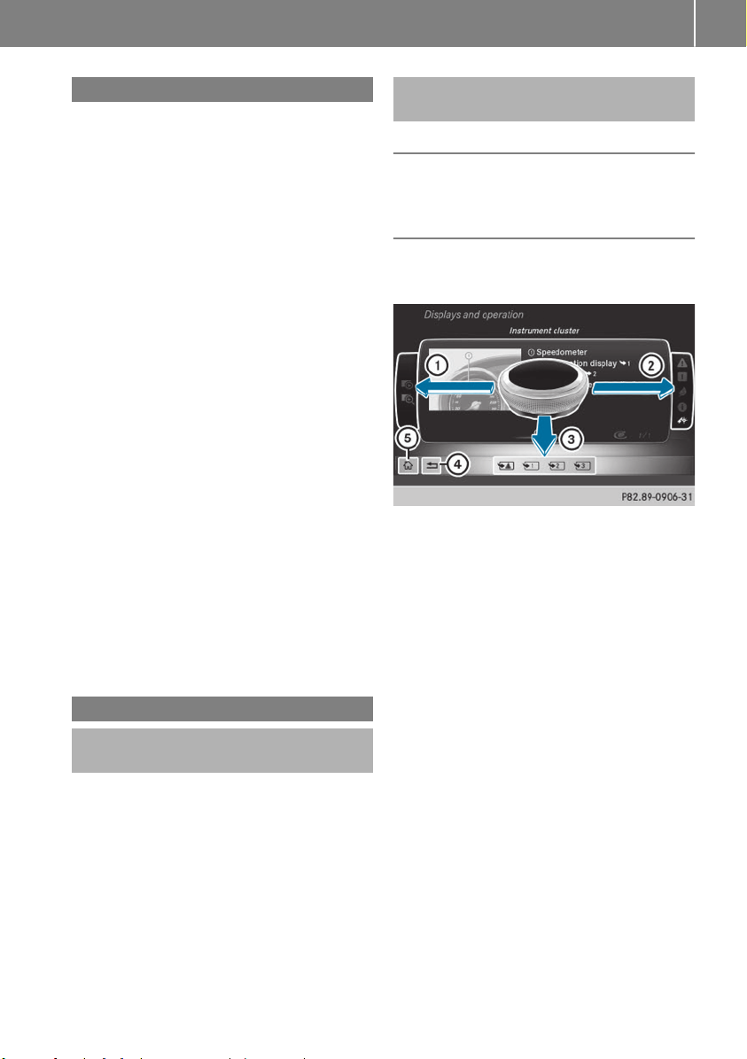
Digital Operator's Manual
21
Introduction
The printed Operator's Manual provides information about the safe operation of your vehicle.
The Digital Operator's Manual provides comprehensive and specifically adapted information on
your vehicle's equipment and multimedia system. You can call up the Digital Operator's Manual via the multimedia system.
You will not incur any costs when calling up
i
the Digital Operator's Manual. The Digital
Operator's Manual works without connecting
to the Internet.
There are three ways to access the topics of the
Digital Operator's Manual:
R
Visual search
The visual search allows you to explore your
vehicle "virtually". Starting from either the
vehicle exterior view or interior view, you can
access many of the different topics covered
by the Digital Operator's Manual. To access
the vehicle interior section, select the "Vehicle interior" view.
R
Keyword search
The keyword search allows you to search for a
keyword by entering characters.
R
Contents
You can select individual sections in the contents.
The Digital Operator's Manual is deactiva-
i
ted for safety reasons while driving.
Operation
Calling up the Digital Operator's Manual
X
Press the Ø button in the center console.
The overview relating to the vehicle appears.
X
Select the "Operator's Manual" menu item by
turning 3 or pressing 7 the controller.
X
Confirm 7 the message about the warning
and safety notes.
The basic menu for the Digital Operator's
Manual appears.
Operating the Digital Operator's Manual
General notes
Please observe the information about the operation of the controller (Y page 202).
Content pages
The content pages can be accessed by means of
a visual search, a keyword search or using the
contents.
X
To scroll forwards/backwards: turn 3
the controller.
X
To display in full-screen or animation: slide
8 the controller to the left :.
To select information texts or save book-
X
marks: slide 9 the controller to the
right ;.
X
To select a link: slide 6 the controller
downwards =.
X
To exit a content page: select % sym-
bol ?.
To call up the basic menu of the Digital
X
Operator's Manual: select Þ symbol A.
To switch functions to the multimedia
X
system using the buttons on the center
console: press the $, %, Õ or Ø
button.
The selected menu appears. The Digital Operator's Manual remains open in the background.
Page 24

Genuine Mercedes-Benz parts
22
Protecting the environment
General notes
Environmental note
H
Daimler's declared policy is one of comprehensive environmental protection.
Our objectives are to use the natural resources which form the basis of our existence on
Introduction
this planet sparingly and in a manner which
takes the requirements of both nature and
humanity into consideration.
You too can help to protect the environment
by operating your vehicle in an environmentally-responsible manner.
Energy consumption and the rate of engine,
transmission, brake and tire wear depend on
the following factors:
R
operating conditions of your vehicle
R
your personal driving style
You can influence both factors. Therefore,
please bear the following in mind:
Operating conditions:
R
observe the correct tire pressure.
R
avoid carrying unnecessary weight.
R
remove the roof rack once you no longer
need it.
R
a regularly serviced vehicle will contribute
to environmental protection. You should
therefore adhere to the service intervals.
R
all maintenance work should be carried out
at a qualified specialist workshop.
Personal driving style:
R
drive carefully and maintain a safe distance
from the vehicle in front.
R
avoid frequent, sudden acceleration and
braking.
R
monitor the vehicle's energy consumption.
Environmental note
H
Have a defective high-voltage battery disposed of in an environmentally-responsible
manner. Contact a qualified specialist workshop which has the necessary specialist
knowledge and tools to carry out the work
required. Mercedes-Benz recommends that
you use an authorized Mercedes-Benz Center
for this purpose.
Environmental concerns and recommendations
Wherever the Operator's Manual requires you to
dispose of materials, first try to regenerate or reuse them. Observe the relevant environmental
rules and regulations when disposing of materials. In this way you will help to protect the environment.
Genuine Mercedes-Benz parts
Environmental note
H
Daimler AG also supplies reconditioned major
assemblies and parts which are of the same
quality as new parts. They are covered by the
same Limited Warranty entitlements as new
parts.
Air bags and Emergency Tensioning Devi-
!
ces, as well as control units and sensors for
these restraint systems, may be installed in
the following areas of your vehicle:
R
doors
R
door pillars
R
door sills
R
seats
R
cockpit
R
instrument cluster
R
center console
Do not install accessories such as audio systems in these areas. Do not carry out repairs
or welding. You could impair the operating
efficiency of the restraint systems.
Have aftermarket accessories installed at a
qualified specialist workshop.
You could jeopardize the operating safety of
your vehicle if you use parts, tires and wheels as
well as accessories relevant to safety which
have not been approved by Mercedes-Benz. This
could lead to malfunctions in safety-relevant
systems, e.g. the brake system. Use only genuine Mercedes-Benz parts or parts of equal qual-
Page 25

Service and vehicle operation
23
ity. Only use tires, wheels and accessories that
have been specifically approved for your vehicle.
Genuine Mercedes-Benz parts are subject to
strict quality control. Every part has been specifically developed, manufactured or selected
for and adapted to Mercedes-Benz vehicles.
Therefore, only genuine Mercedes-Benz parts
should be used.
More than 300,000 different genuine
Mercedes-Benz parts are available for
Mercedes-Benz models.
All authorized Mercedes-Benz Centers maintain
a supply of genuine Mercedes-Benz parts for
necessary service and repair work. In addition,
strategically located parts delivery centers provide quick and reliable parts service.
Always specify the vehicle identification number
(VIN) when ordering genuine Mercedes-Benz
parts (Y page 282).
Operator's Manual
Vehicle equipment
This Operator's Manual describes all models
i
and all standard and optional equipment of
your vehicle available at the time of going to
print. Country-specific differences are possible. Bear in mind that your vehicle may not
feature all functions described here. This also
applies to safety-relevant systems and functions. The equipment in your vehicle may
therefore differ from that shown in the
descriptions and illustrations.
The original purchase agreement lists all systems installed in your vehicle.
Should you have any questions concerning
equipment and operation, please consult an
authorized Mercedes-Benz Center.
The Operator's Manual and Maintenance Booklet are important documents and should be kept
in the vehicle.
Service and vehicle operation
Warranty
The Limited Warranty for your vehicle applies in
accordance with the warranty terms and conditions in the Service and Warranty Information
booklet.
Your authorized Mercedes-Benz Center will
replace and repair all factory-installed parts in
accordance with the following warranty terms
and conditions:
R
New Vehicle Limited Warranty
R
State warranty enforcement laws (lemon
laws)
Replacement parts and accessories are covered
by the Mercedes-Benz Parts and Accessories
warranties. These are available at any authorized Mercedes-Benz Center.
Should you lose your Service and Warranty
i
Information booklet, have an authorized
Mercedes-Benz Center arrange for a replacement. The new Service and Warranty Information booklet will be posted to you.
Information for customers in California
Under California law you may be entitled to a
replacement of your vehicle or a refund of the
purchase price or lease price, if after a reasonable number of repair attempts Mercedes-Benz
USA, LLC and/or its authorized repair or service
facilities fail to fix one or more substantial
defects or malfunctions in the vehicle that are
covered by its express warranty.
During the period of 18 months from original
delivery of the vehicle or the accumulation of
18,000 miles (approximately 29,000 km) on the
odometer of the vehicle, whichever occurs first,
a reasonable number of repair attempts is presumed for a retail buyer or lessee if one or more
of the following occurs:
(1) the same substantial defect or malfunction
results in a condition that is likely to cause
death or serious bodily injury if the vehicle is
driven, that defect or malfunction has been
subject to repair two or more times, and you
have directly notified Mercedes-Benz USA,
LLC in writing of the need for its repair.
(2) the same substantial defect or malfunction
of a less serious nature than category (1)
has been subject to repair four or more
times and you have directly notified
Mercedes-Benz in writing of the need for its
repair.
(3) the vehicle is out of service by reason of
repair of the same or different substantial
Z
Introduction
Page 26

Operating safety
24
defects or malfunctions for a cumulative
total of more than 30 calendar days.
Please send your written notice to:
Customer Assistance Center
Mercedes-Benz USA, LLC
3 Mercedes Drive
Montvale, NJ 07645-0350
Introduction
Maintenance
Always bring the Maintenance Booklet with you
when taking the vehicle to an authorized
Mercedes-Benz Center. Your customer service
advisor will enter every service into your Maintenance Booklet on your behalf.
Roadside Assistance
The Mercedes-Benz Roadside Assistance Program offers technical help in the event of a
breakdown. Calls to the toll-free Roadside Assistance Hotline are answered by our agents 24
hours a day, 365 days a year.
1-800-FOR-MERCedes(1-800-367-6372)
(USA)
1-800-387-0100(Canada)
For additional information, refer to the
Mercedes-Benz Roadside Assistance Program
brochure (USA) or the "Roadside Assistance"
section in the Service and Warranty Booklet
(Canada). You will find both in the vehicle document wallet.
Change of address or change of ownership
In the event of a change of address, please send
us the "Notification of Address Change" in the
Service and Warranty Booklet or simply call the
Mercedes-Benz Customer Assistance Center
(USA) at the hotline number
1-800-FOR-MERCedes (1-800-367-6372) or
Customer Service Center (Canada) at
1-800-387-0100. This will assist us in contacting you in a timely manner should the need arise.
If you sell your Mercedes, please leave all literature in the vehicle so that it is available to the
next owner.
If you have purchased a used car, please send us
the "Notification of Used Car Purchase" in the
Service and Warranty Booklet or simply call the
Mercedes-Benz Customer Assistance Center
(USA) at the hotline number
1-800-FOR-MERCedes (1-800-367-6372) or
Customer Service (Canada) at 1-800-387-0100.
Vehicle operation outside the USA
If you drive your vehicle abroad, please note that
service facilities or replacement parts may not
be immediately available.
Some Mercedes-Benz models are available for
delivery in Europe through our European Delivery Program. Please consult an authorized
Mercedes-Benz Center for further information,
or write to the following address:
Mercedes-Benz USA, LLC
European Delivery Department
One Mercedes Drive
Montvale, NJ 07645-0350
Operating safety
Important safety notes
Important safety notes
WARNING
G
If you do not have the prescribed service/
maintenance work or any required repairs
carried out, this can result in malfunctions or
system failures. There is a risk of an accident.
Always have the prescribed service/maintenance work as well as any required repairs
carried out at a qualified specialist workshop.
WARNING
G
Modifications to electronic components, their
software as well as wiring can impair their
function and/or the function of other networked components. In particular, systems
relevant to safety could also be affected. As a
result, these may no longer function as intended and/or jeopardize the operating safety of
the vehicle. There is an increased risk of an
accident and injury.
Never tamper with the wiring as well as electronic components or their software. You
Page 27
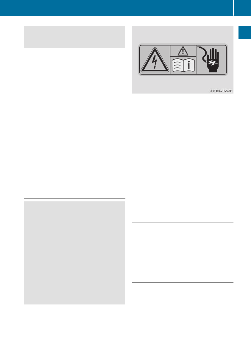
should have all work to electrical and electronic equipment carried out at a qualified
specialist workshop.
There is a risk of damage to the vehicle if:
!
R
the vehicle becomes stuck, e.g. on a high
curb or an unpaved road
R
you drive too fast over an obstacle, e.g. a
curb, speed bumps or a pothole in the road
R
a heavy object strikes the underbody or
parts of the chassis
In situations like this, the body, the underbody, chassis parts, wheels or tires could be
damaged without the damage being visible.
Components damaged in this way can unexpectedly fail or, in the case of an accident, no
longer withstand the strain they are designed
to.
In such situations, have the vehicle checked
and repaired immediately at a qualified specialist workshop. If on continuing your journey you notice that driving safety is impaired,
pull over and stop the vehicle immediately,
paying attention to road and traffic conditions. In such cases, consult a qualified specialist workshop.
Danger of electric shock
DANGER
G
The vehicle's high-voltage electrical system is
under high voltage. If you modify components
in the vehicle's high-voltage electrical system
or touch damaged components, you may be
electrocuted. The components in the vehicle's high-voltage electrical system may be
damaged in an accident, although the damage
is not visible. There is a risk of fatal injury.
Following an accident, do not touch any highvoltage components and never modify the
vehicle's high-voltage electrical system. Have
the vehicle towed away after an accident and
the vehicle's high-voltage electrical system
checked by a qualified specialist workshop.
Operating safety
All of the vehicle's high-voltage electrical system components are marked with yellow warning stickers which warn you about high voltages.
The cables of the vehicle's high-voltage electrical system are orange.
When towing a vehicle after an accident, be sure
to observe the following sections:
R
Transporting the vehicle (Y page 254)
R
Towing the vehicle with the front axle raised
(Y page 253)
R
Towing a vehicle with both axles on the
ground (Y page 253)
Read the important safety instructions on towing away (Y page 251).
The ignition must be switched off when carrying
out general tasks, such as changing bulbs or
checking the coolant level.
Automatic switching off of the vehicle's
high-voltage electrical system
If the restraint systems are activated during an
accident, the vehicle's high-voltage electrical
system is automatically deactivated.
This is to ensure that you do not come into contact with high voltage.
Automatic protection from switching
on of the vehicle's high-voltage electrical system
The vehicle's high-voltage electrical system is
not activated when the vehicle is started if:
R
a serious electrical insulation malfunction is
detected in the vehicle's high-voltage electrical system
R
an electrical connection in the vehicle's highvoltage electrical system is disconnected
25
Introduction
Z
Page 28
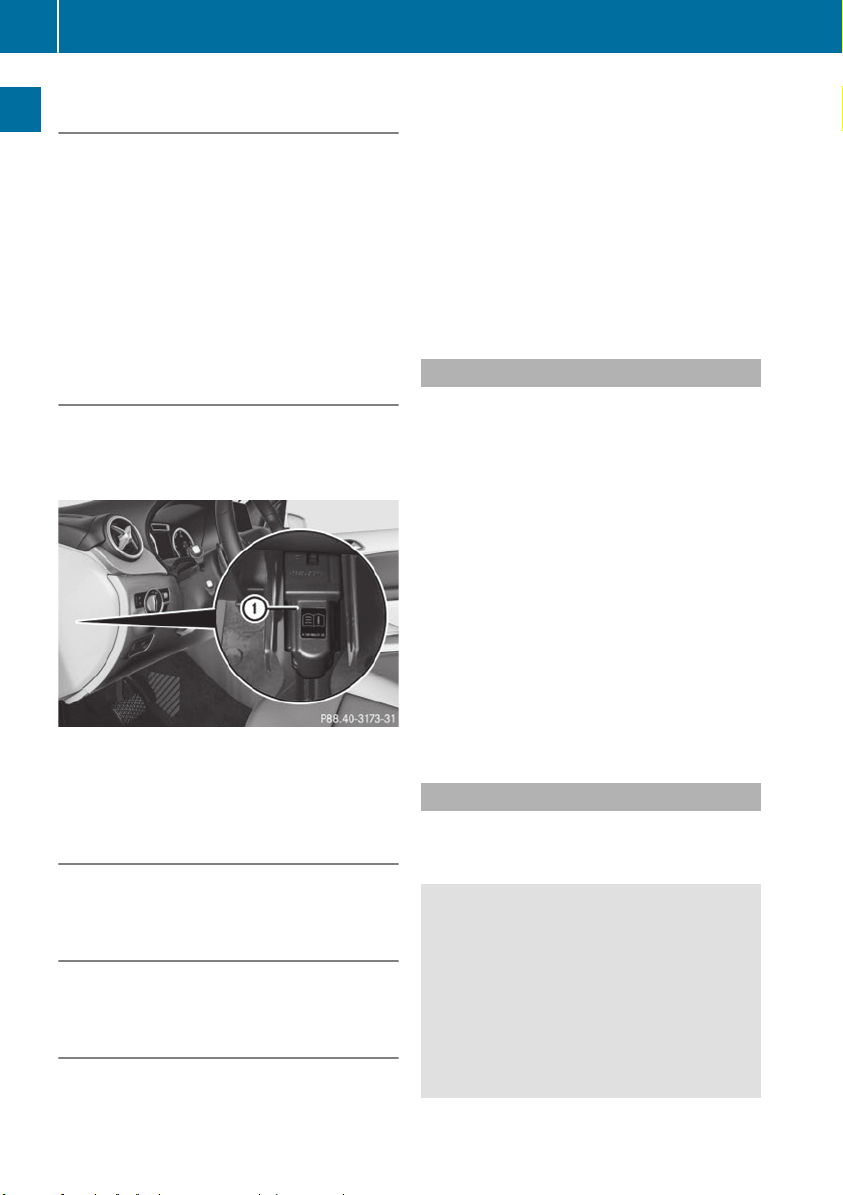
Operating safety
26
Automatic switching off of the charging
process
The charging process is deactivated automatically if:
R
the high-voltage battery is fully charged
The charging process is interrupted automatically if:
R
a serious electrical insulation malfunction is
Introduction
detected in the vehicle's high-voltage electrical system
R
an electrical connection in the vehicle's highvoltage electrical system is disconnected
High-voltage switch-off device
The high-voltage system must only be
!
switched off at vehicle standstill by specially
trained service engineers. Otherwise the
high-voltage system may be damaged.
Your vehicle is equipped with a high-voltage
switch-off device : which can be used to
switch off the vehicle's high-voltage electrical
system.
Mobile phone antenna
It is not permitted to retrofit a mobile phone
!
antenna.
Trailer tow hitch
Retrofitting a trailer tow hitch is not permis-
!
sible.
Warning
Vehicles with an electric motor generate much
less driving noise than vehicles with internal
combustion engines. As a result, your vehicle
may not be heard by other road users until it is
very close to them, or it may not be heard at all.
This is particularly the case if other road users
have not yet seen your vehicle but are instead
relying on hearing. Drive with particular care,
allowing for the possibility that other road users
may behave unpredictably.
The vehicle is equipped with a sound generator.
The sound generator is activated so that other
road users can hear your vehicle better. The
sound generator is activated at speeds of under
20 mph (30 km/h) and switches off automatically at higher speeds.
Declarations of conformity
USA: "The wireless devices of this vehicle com-
ply with Part 15 of the FCC Rules. Operation is
subject to the two following two conditions: 1)
These devices may not cause harmful interference, and 2) These devices must accept any
interference received, including interference
that may cause undesired operation. Changes
or modifications not expressly approved by the
party responsible for compliance could void the
user’s authority to operate the equipment."
Canada: "The wireless devices of this vehicle
comply with Industry Canada license-exempt
RSS standard(s). Operation is subject to the following two conditions: (1) These devices may
not cause interference, and (2) These devices
must accept any interference, including interference that may cause undesired operation of
the device."
Diagnostics connection
The diagnostics connection is only intended for
the connection of diagnostic equipment at a
qualified specialist workshop.
WARNING
G
If you connect equipment to a diagnostics
connection in the vehicle, it may affect the
operation of vehicle systems. As a result, the
operating safety of the vehicle could be affected. There is a risk of an accident.
Only connect equipment to a diagnostics connection in the vehicle, which is approved for
your vehicle by Mercedes-Benz.
Page 29

Operating safety
27
WARNING
G
Objects in the driver's footwell can restrict the
pedal travel or obstruct a depressed pedal.
The operating and road safety of the vehicle is
jeopardized. There is a risk of an accident.
Make sure that all objects in the vehicle are
stowed correctly, and that they cannot enter
the driver's footwell. Install the floormats
securely and as specified in order to ensure
sufficient clearance for the pedals. Do not use
loose floormats and do not place floormats on
top of one another.
If equipment on the diagnostics connection
!
is used, the starter battery may discharge.
Qualified specialist workshop
An authorized Mercedes-Benz Center is a qualified specialist workshop. It has the necessary
specialist knowledge, tools and qualifications to
correctly carry out the work required on your
vehicle. This is especially the case for work relevant to safety.
Observe the notes in the Maintenance Booklet.
Always have the following work carried out at an
authorized Mercedes-Benz Center:
R
work relevant to safety
R
service and maintenance work
R
repair work
R
alterations, installation work and modifications
R
work on electronic components
R
work on the drive system
Correct use
If you remove any warning stickers, you or others could fail to recognize certain dangers.
Leave warning stickers in position.
Observe the following information when driving
your vehicle:
R
the safety notes in this manual
R
technical data for the vehicle
R
traffic rules and regulations
R
laws and safety standards pertaining to motor
vehicles
Problems with your vehicle
If you should experience a problem with your
vehicle, particularly one that you believe may
affect its safe operation, we urge you to contact
an authorized Mercedes-Benz Center immediately to have the problem diagnosed and rectified. If the problem is not resolved to your satisfaction, please discuss the problem again with
an authorized Mercedes-Benz Center or, if necessary, contact us at one of the following
addresses.
In the USA
Customer Assistance Center
Mercedes-Benz USA, LLC
3 Mercedes Drive
Montvale, NJ 07645-0350
In Canada
Customer Relations Department
Mercedes-Benz Canada, Inc.
98 Vanderhoof Avenue
Toronto, Ontario M4G 4C9
Reporting safety defects
USA only:
The following text is reproduced as required of
all manufacturers under Title 49, Code of U.S.
Federal Regulations, Part 575 pursuant to the
National Traffic and Motor Vehicle Safety Act of
1966.
If you believe that your vehicle has a defect
which could cause a crash or could cause injury
or death, you should immediately inform the
National Highway Traffic Safety Administration
(NHTSA) in addition to notifying Mercedes-Benz
USA, LLC.
If NHTSA receives similar complaints, it may
open an investigation, and if it finds that a safety
defect exists in a group of vehicles, it may order
a recall and remedy campaign. However, NHTSA
cannot become involved in individual problems
between you, your dealer, or Mercedes-Benz
USA, LLC.
To contact NHTSA, you may call the Vehicle
Safety Hotline toll-free at 1-888-327-4236
(TTY: 1-800-424-9153); go to http://
www.safercar.gov; or write to: Administrator,
NHTSA, 400 Seventh Street, SW., Washington,
DC 20590.
Introduction
Z
Page 30

Data stored in the vehicle
28
You can also obtain other information about
motor vehicle safety from
http://www.safercar.gov
Limited Warranty
Follow the instructions in this manual about
!
the proper operation of your vehicle as well as
about possible vehicle damage. Damage to
Introduction
your vehicle that arises from culpable contraventions against these instructions is not covered either by the Mercedes-Benz Limited
Warranty or by the New or Used-Vehicle Warranty.
QR codes for the rescue card
The QR codes are secured in the fuel filler flap
and on the opposite side on the B-pillar. In the
event of an accident, rescue services can use
the QR code to quickly find the appropriate rescue card for your vehicle. The current rescue
card contains the most important information
about your vehicle in a compact form, e.g. the
routing of the electric cables.
You can find more information under
www.mercedes-benz.de/qr-code.
Data stored in the vehicle
Data storage
A wide range of electronic components in your
vehicle contain data memories.
These data memories temporarily or permanently store technical information about:
R
the vehicle's operating state
R
incidents
R
malfunctions
In general, this technical information documents the state of a component, a module, a
system or the surroundings.
These include, for example:
R
operating conditions of system components,
e.g. fluid levels
R
the vehicle's status messages and those of its
individual components, e.g. number of wheel
revolutions/speed, deceleration in move-
ment, lateral acceleration, accelerator pedal
position
R
malfunctions and defects in important system
components, e.g. lights, brakes
R
vehicle reactions and operating conditions in
special driving situations, e.g. air bag deployment, intervention of stability control systems
R
ambient conditions, e.g. outside temperature
This data is of an exclusively technical nature
and can be used to:
R
assist in recognizing and rectifying malfunctions and defects
R
analyze vehicle functions, e.g. after an accident
R
optimize vehicle functions
The data cannot be used to trace the vehicle's
movements.
When your vehicle is serviced, technical information can be read from the event data memory
and malfunction data memory.
Services include, for example:
R
repair services
R
service processes
R
warranties
R
quality assurance
The vehicle is read out by employees of the service network (including the manufacturer) using
special diagnostic testers. More detailed information is obtained from it, if required.
After a malfunction has been rectified, the information is deleted from the malfunction memory
or is continually overwritten.
When operating the vehicle, situations are conceivable in which this technical data, in connection with other information (if necessary, under
consultation with an authorized expert), could
be traced to a person.
Examples include:
R
accident reports
R
damage to the vehicle
R
witness statements
Further additional functions that have been contractually agreed upon with the customer allow
certain vehicle data to be conveyed by the vehicle as well. The additional functions include, for
example, vehicle location in case of an emergency.
Page 31

Information on copyright
29
COMAND/mbrace
If the vehicle is equipped with COMAND or
mbrace, additional data about the vehicle's
operation, the use of the vehicle in certain situations, and the location of the vehicle may be
compiled through COMAND or the mbrace system.
For additional information please refer to the
COMAND User Manual or the Digital Operator's
Manual and/or the mbrace Terms and Conditions.
Event data recorders
This vehicle is equipped with an event data
recorder (EDR). This vehicle is equipped with an
event data recorder (EDR). The main purpose of
an EDR is to record, in certain crash or near
crash-like situations, such as an air bag deployment or hitting a road obstacle, data that will
assist in understanding how a vehicle's systems
performed. The EDR is designed to record data
related to vehicle dynamics and safety systems
for a short period of time, typically 30 seconds
or less.
The EDR in this vehicle is designed to record
such data as:
R
How various systems in your vehicle were
operating
R
Whether or not the driver and passenger
safety belts were buckled/fastened
R
How far (if at all) the driver was depressing the
accelerator and/or brake pedal and
R
How fast the vehicle was traveling.
These data can help provide a better understanding of the circumstances in which crashes
and injuries occur. NOTE: EDR data are recorded
by your vehicle only if a non-trivial crash situation occurs; no data are recorded by the EDR
under normal driving conditions and no personal
data (e.g. name, gender, age and crash location)
are recorded. However, other parties, such as
law enforcement could combine the EDR data
with the type of personally identifying data routinely acquired during a crash investigation.
Access to the vehicle and/or the EDR is needed
to read data that is recorded by an EDR, and
special equipment is required. In addition to the
vehicle manufacturer, other parties that have
the special equipment, such as law enforcement, can read the information by accessing the
vehicle or the EDR.
EDR data may be used in civil and criminal matters as a tool in accident reconstruction, accident claims and vehicle safety. Since the Crash
Data Retrieval CDR tool that is used to extract
data from the EDR is commercially available,
Mercedes-Benz USA, LLC ("MBUSA") expressly
disclaims any and all liability arising from the
extraction of this information by unauthorized
Mercedes-Benz personnel.
MBUSA will not share EDR data with others
without the consent of the vehicle owners or, if
the vehicle is leased, without the consent of the
lessee. Exceptions to this representation
include responses to subpoenas by law enforcement; by federal, state or local government; in
connection with or arising out of litigation involving MBUSA or its subsidiaries and affiliates; or,
as required by law.
Warning: The EDR is a component of the
Restraint System Module. Tampering with, altering, modifying or removing the EDR component
may result in a malfunction of the Restraint System Module and other systems.
State laws or regulations regarding EDRs that
conflict with federal regulation are pre-empted.
This means that in the event of such conflict, the
federal regulation governs. As of February 2013,
13 states have enacted laws relating to EDRs.
Information on copyright
General information
Information on license for free and open-source
software used in your vehicle and its electronic
components is available on the following website:
http://www.mercedes-benz.com/opensource
Registered trademarks
R
Bluetooth®is a registered trademark of Bluetooth SIG Inc.
R
DTS™ is a registered trademark of DTS, Inc.
R
Dolby®and MLP™ are registered trademarks
of DOLBY Laboratories.
R
BabySmart™, ESP®and PRE-SAFE®are registered trademarks of Daimler AG.
R
HomeLink®is a registered trademark of Johnson Controls.
Z
Introduction
Page 32

Information on copyright
30
R
iPod®and iTunes®are registered trademarks
of Apple Inc.
R
Logic7®is a registered trademark of Harman
International Industries.
R
Microsoft®and Windows media®are registered trademarks of Microsoft Corporation.
R
SIRIUS®is a registered trademark of Sirius
XM Radio Inc.
R
HD Radio™ is a registered trademark of iBiq-
Introduction
uity Digital Corporation.
R
Gracenote®is a registered trademark of
Gracenote, Inc.
R
ZAGAT Survey®and related brands are registered trademarks of Zagat Survey, LLC.
Page 33

Cockpit
Cockpit
31
At a glance
Function Page
:
Steering wheel paddle shifters 115
;
Combination switch 88
=
Instrument cluster 32
?
Horn
A
DIRECT SELECT lever 112
B
Parking Assist PARKTRONIC
warning display 140
C
Overhead control panel 37
Function Page
D
Climate control systems 99
E
Ignition lock 109
F
Adjusts the steering wheel 83
G
Cruise control lever 136
H
Electric parking brake 130
I
Light switch 87
J
Diagnostics connection 26
K
Opens the hood 231
Page 34

Instrument cluster
32
Instrument cluster
At a glance
Function Page
:
Speedometer with segments
Warning and indicator lamps:
L Low-beam headlamps
T Parking lamps
K High-beam headlamps
÷ ESP
F Electric parking brake
applied (red) 198
! Electric parking brake
(yellow)
· Distance warning
J Brakes (yellow)
å ESP®OFF
! ABS malfunctioning
$ Brakes (red)
;
#! Turn signals
=
Multifunction display 155
with outside temperature
display 152
®
87
88
88
195
198
199
192
195
193
192
88
Function Page
?
Power display 153
Warning and indicator lamps:
6 Restraint system
ü Seat belt not fastened
é RBS (Recuperative
Brake System) 192
R Rear fog lamp
; Drive system
h Tire pressure monitor
A
E-CELL display 152
B
Display for the condition of
charge of the high-voltage
battery 153
Ý High-voltage battery
reserve 181
198
190
88
181
200
Page 35

Multifunction steering wheel
Multifunction steering wheel
33
At a glance
Function Page
:
Multifunction display 155
;
Multimedia system display
=
~ Rejects or ends a call
6 Makes or accepts a call
Further telephone functions 160
WXAdjusts volume
8 Mute
? Switches on voice-
operated control of the navigation system or the Voice
Control System
i Invehicles with multimedia system Audio 20
you can find further information:
R
on the multimedia system in the Digital
Operator's Manual
R
on voice-operated control of the navigation
system in the manufacturer's operating
instructions
Function Page
?
ò Opens the menu list
9:Selects a menu
a Confirms the selection
% Back
Operates the on-board com-
puter 154
? Switches off voice-
operated control of the navigation system or the Voice
Control System
i In vehicles with multimedia system
COMAND you can find further information:
R
on the multimedia system in the Digital
Operator's Manual
R
on the DVD changer or single DVD drive in
the Digital Operator's Manual
R
on the Voice Control System in the separate operating instructions
Page 36

Center console
34
Center console
Center console, upper section
At a glance
Function Page
:
Multimedia system (see the
separate operating instructions)
;
c Seat heating
=
c Parking Assist
PARKTRONIC 141
?
Activates RANGE PLUS 120
82
Function Page
A
£ Hazard warning lamps
B
PASSENGER AIR BAG indicator lamp 39
C
Selects the drive program 114
D
& Pre-entry climate control 105
89
Page 37

Center console, lower section
Center console
35
At a glance
Function Page
:
Ashtray 217
Cigarette lighter 218
Socket 218
Stowage compartment 207
;
Stowage compartment 207
=
Cup holder 216
Function Page
?
Stowage compartment with
Media Interface 207
A
Multimedia system controller (see the separate operating instructions)
Page 38

Door control panel
36
Door control panel
At a glance
Function Page
:
Opens the door 72
;
%&Unlocks/locks
the vehicle
=
r45= Saves
the seat and exterior mirror
settings 85
?
Adjusts the seats electrically 80
A
7 Z ö \
Adjusts and folds the exterior
mirrors in/out electrically 84
72
Function Page
B
W Opens/closes the side
windows
C
n Activates/deactivates
the override feature for the
side windows in the rear
compartment 58
76
Page 39

Overhead control panel
Overhead control panel
37
At a glance
Function Page
:
u Switches the rear compartment interior lighting
on/off
;
p Switches the righthand reading lamp on/off 89
=
| Switches the front interior lighting/automatic interior lighting control off 89
?
ï MB Info call button
(mbrace system)
A
Rear-view mirror 84
B
Sets the compass 228
89
221
Function Page
C
Buttons for the garage door
opener 226
D
F Roadside assistance
call button (mbrace system)
E
G SOS button (mbrace
system) 220
F
Eyeglasses compartment 208
G
c Switches the front interior lighting on 89
H
p Switches the left-hand
reading lamp on/off
221
89
Page 40

Occupant safety
38
Panic alarm
Safety
X
To activate: press and hold the
! button : for approx. one second.
A visual and audible alarm is triggered if the
alarm system is armed.
X
To deactivate: press ! button : again.
or
X
Insert the SmartKey into the ignition lock.
or, in vehicles with KEYLESS-GO start-function
or KEYLESS‑GO
X
Press the Start/Stop button.
The SmartKey must be in the vehicle.
Occupant safety
Introduction to the restraint system
The restraint system can reduce the risk of vehicle occupants coming into contact with parts of
the vehicle's interior in the event of an accident.
The restraint system can also reduce the forces
to which vehicle occupants are subjected during
an accident.
The restraint system comprises:
R
seat belt system
R
air bags
R
child restraint system
R
child seat securing systems
The components of the restraint system work in
conjunction with each other. They can only
deploy their protective function if, at all times, all
vehicle occupants:
R
have fastened their seat belts correctly
(Y page 41)
R
have adjusted their seat and head restraint
properly (Y page 79).
As the driver, you also have to make sure that
the steering wheel is adjusted correctly.
Observe the information relating to the correct
driver's seat position (Y page 79).
You also have to make sure that an air bag can
inflate properly if deployed (Y page 43).
An air bag supplements a correctly worn seat
belt. As an additional safety device, the air bag
increases the level of protection for vehicle
occupants in the event of an accident. For example, if, in the event of an accident, the protection
offered by the seat belt is sufficient, the air bags
are not deployed. When an accident occurs, only
the air bags that increase protection in that particular accident situation are deployed. However, seat belts and air bags generally do not
protect against objects penetrating the vehicle
from the outside.
Information on restraint system operation can
be found under "Triggering of the Emergency
Tensioning Devices and air bags" (Y page 50).
For information on children traveling with you in
the vehicle and on child restraint systems, see
"Children in the vehicle" (Y page 52).
Important safety notes
WARNING
G
Modifications to the restraint system may
cause it to no longer work as intended. The
restraint system may then not perform its
intended protective function and may fail in an
accident or trigger unexpectedly, for example.
This poses an increased risk of injury or even
fatal injury.
Never modify parts of the restraint system.
Never tamper with the wiring, the electronic
components or their software.
If it is necessary to modify components of the
restraint system to accommodate a person
with disabilities, contact an authorized
Mercedes-Benz Center for details. USA only:
for further information contact our Customer
Assistance Center at 1-800-FOR-MERCedes
(1‑800‑367‑6372).
Mercedes-Benz recommends that you only use
driving aids which have been approved specifically for your vehicle by Mercedes-Benz.
Page 41

Occupant safety
39
Restraint system warning lamp
The functions of the restraint system are
checked after the ignition is switched on and at
regular intervals while the drive system is running. Therefore, malfunctionscan be detected in
good time.
The 6 restraint system warning lamp in the
instrument cluster lights up when the ignition is
switched on. It goes out no later than a few seconds after the vehicle is started. The components of the restraint system are in operational
readiness.
A malfunction has occurred if the 6 restraint
system warning lamp:
R
does not light up after the ignition is switched
on
R
does not go out after a few seconds with the
drive system running
R
lights up again while the drive system is running
DANGER
G
If the restraint system is malfunctioning,
restraint system components may be triggered unintentionally or may not deploy as
intended during an accident. This can affect
for example the Emergency Tensioning
Device or the air bag. Furthermore, in the
event of an accident, the vehicle's high-voltage electrical system may not be deactivated
as intended. You may be electrocuted if you
touch the damaged components of the vehicle's high-voltage electrical system. This
poses an increased risk of injury or even fatal
injury.
Have the restraint system checked and
repaired in a qualified specialist workshop as
soon as possible. After an accident, switch off
the ignition immediately and remove the key
from the ignition lock.
PASSENGER AIR BAG indicator lamp
PASSENGER AIR BAG ON indicator lamp : and
PASSENGER AIR BAG OFF indicator lamp ; are
part of the Occupant Classification System
(OCS).
The indicator lamps display the status of the
front-passenger front air bag.
R
PASSENGER AIR BAG ON lights up for 60 seconds, subsequently both indicator lamps are
off (PASSENGER AIR BAG ON and OFF): the
front-passenger front air bag is able to deploy
in the event of an accident.
R
PASSENGER AIR BAG OFF lights up: the frontpassenger front air bag is deactivated. It will
then not be deployed in the event of an accident.
If the PASSENGER AIR BAG ON indicator lamp is
off, only the PASSENGER AIR BAG OFF indicator
lamp shows the status of the front-passenger
front air bag. The PASSENGER AIR BAG OFF
indicator lamp may be lit continuously or be off.
Depending on the person in the front-passenger
seat, the front-passenger front air bag must
either be deactivated or enabled; see the following points. You must make sure of this both
before and during a journey.
R
Children in a child restraint system:
whether the front-passenger front air bag is
enabled or deactivated depends on the installed child restraint system, and the age and
size of the child. Therefore, be sure to observe
the notes on the "Occupant Classification
System (OCS)" (Y page 45) and on "Children in the vehicle" (Y page 52). There you
will also find instructions on rearward and
forward-facing child restraint systems on the
front-passenger seat.
R
All other persons: depending on the classification of the person in the front-passenger
seat, the front-passenger front air bag is ena-
Safety
Z
Page 42

Occupant safety
40
bled or deactivated (Y page 45). Be sure to
observe the notes on "Seat
belts“ (Y page 40) and "Air bags"
(Y page 43). There you can also find information on the correct seat position.
Seat belts
Introduction
Seat belts are the most effective means of
restricting the movement of vehicle occupants
Safety
in the event of an accident or the vehicle rolling
over. This reduces the risk of vehicle occupants
coming into contact with parts of the vehicle
interior or being ejected from the vehicle. Furthermore, the seat belt helps to keep the vehicle
occupant in the best position in relation to the
air bag.
The seat belt system comprises:
R
Seat belts
R
Emergency Tensioning Devices for the front
seat belts and the outer seat belts in the rear
R
Seat belt force limiters for the front seat belts
and the outer seat belts in the rear
If the seat belt is pulled out of the belt outlet
quickly or with a jerky movement, the belt
retractor locks. The belt strap cannot be extracted any further.
The Emergency Tensioning Device tightens the
seat belt in an accident, pulling the belt close
against the body. However it does not pull the
vehicle occupant back in the direction of the
backrest.
The Emergency Tensioning Device does not correct an incorrect seat position or the routing of
an incorrectly fastened seat belt.
When triggered, a seat belt force limiter helps to
reduce the force exerted by the seat belt on the
vehicle occupant.
The seat belt force limiters for the front seats are
synchronized with the front air bags, which
absorb part of the deceleration force. This can
reduce the force exerted on the vehicle occupants during an accident.
If the front-passenger seat is unoccupied,
!
do not insert the belt tongue into the buckle of
the front-passenger seat. This may otherwise
lead to the triggering of the Emergency Tensioning Device in the event of an accident,
which will then need to be replaced.
Important safety notes
The use of seat belts and child restraint systems
is required by law in:
R
all 50 states
R
the U.S. territories
R
the District of Columbia
R
all Canadian provinces
Even where this is not required by law, all vehicle
occupants should correctly fasten their seat
belts before starting the journey.
WARNING
G
If the seat belt is not worn correctly, it cannot
perform its intended protective function. An
incorrectly fastened seat belt can also cause
injuries, for example, in the event of an accident or when braking or changing direction
abruptly. This poses an increased risk of injury
or even fatal injury.
Always ensure that all vehicle occupants have
their seat belts fastened correctly and are sitting properly.
WARNING
G
The seat belt does not offer the intended level
of protection if you have not moved the backrest to an almost vertical position. When braking or in the event of an accident, you could
slide underneath the seat belt and sustain
abdomen or neck injuries, for example. This
poses an increased risk of injury or even fatal
injury.
Adjust the seat properly before beginning
your journey. Always ensure that the backrest
is in an almost vertical position and that the
shoulder section of your seat belt is routed
across the center of your shoulder.
WARNING
G
Persons less than 5 ft (1.50 m) tall cannot
wear the seat belt correctly without an additional and suitable restraint system. If the
seat belt is not worn correctly, it cannot perform its intended protective function. An
incorrectly fastened seat belt can also cause
injuries, for example, in the event of an accident or when braking or changing direction
Page 43

Occupant safety
41
abruptly. This poses an increased risk of injury
or even fatal injury.
For this reason, always secure persons under
5 ft (1.50 m) tall in suitable additional restraint
systems.
If a child younger than twelve years old and
under 5 ft (1.50 m) in height is traveling in the
vehicle:
R
always secure the child in a child restraint
system suitable for this Mercedes-Benz vehicle. The child restraint system must be appropriate to the age, weight and size of the child
R
always observe the instructions and safety
notes on "Children in the vehicle"
(Y page 52) in addition to the child restraint
system manufacturer's installation and operating instructions
R
always observe the instructions and safety
notes on the "Occupant classification system
(OCS)" (Y page 45)
WARNING
G
The seat belts may not perform their intended
protective function if:
R
they are damaged, modified, extremely
dirty, bleached or dyed
R
the seat belt buckle is damaged or
extremely dirty
R
the Emergency Tensioning Devices, belt
anchorages or inertia reels have been modified.
Seat belts may be damaged in an accident,
although the damage may not be visible, e.g.
due to splinters of glass. Modified or damaged
seat belts may tear or fail, e.g. in an accident.
Modified Emergency Tensioning Devices
could accidentally trigger or fail to deploy
when necessary. This poses an increased risk
of injury or even fatal injury.
Never modify the seat belts, Emergency Tensioning Devices, belt anchorages and inertia
reels. Make sure that the seat belts are
undamaged, not worn out and clean. Following an accident, have the seat belts checked
immediately at a qualified specialist workshop.
Only use seat belts that have been approved for
your vehicle by Mercedes-Benz.
Proper use of the seat belts
Observe the safety notes on the seat belt
(Y page 40).
All vehicle occupants must be wearing the seat
belt correctly before beginning the journey. Also
make sure that all vehicle occupants are always
wearing the seat belt correctly while the vehicle
is in motion.
When fastening the seat belt, always make sure
that:
R
the seat belt tongue is only inserted to the belt
buckle belonging to that seat.
R
the seat belt is tight across your body.
Avoid wearing bulky clothing, e.g. a winter
coat.
R
the seat belt is not twisted.
Only then can the forces which occur be dis-
tributed over the area of the belt.
R
the shoulder section of the belt is always
routed across the center of your shoulder.
The shoulder section of the belt must not
come into contact with your neck or be routed
under your arm. Where possible, adjust the
seat belt to the appropriate height.
R
the lap belt passes tightly and as low down as
possible across your lap.
The lap belt must always be routed across
your hip joints and not across your abdomen.
This applies particularly to pregnant women.
If necessary, push the lap belt down to your
hip joint and pull it tight using the shoulder
section of the belt.
R
the seat belt is not routed across sharp, pointed or fragile objects.
If you have such items located on or in your
clothing, e.g. pens, keys or eyeglasses, store
these in a suitable place.
R
only one person is using a seat belt at a time.
Infants and children must never travel sitting
on the lap of a vehicle occupant. In the event
of an accident, they could be crushed
between the vehicle occupant and seat belt.
R
objects are never secured with a seat belt if
the seat belt is also being used by one of the
vehicle's occupants.
Also ensure that there are never objects
between a person and the seat, e.g. cushions.
Safety
Z
Page 44

Occupant safety
42
Seat belts are only intended to secure and
restrain vehicle occupants. Always observe the
"Loading guidelines" for securing objects, luggage or loads (Y page 207).
Fastening and adjusting the seat belts
Observe the safety notes on the seat belt
(Y page 40)and the notes on correct use of seat
belts (Y page 41).
If the center rear seat belt is being used, also
observe the information about the seat belt for
Safety
the center rear seat (Y page 42).
Basic illustration
X
Adjust the seat (Y page 79).
The seat backrest must be in an almost vertical position.
X
Pull the seat belt smoothly from the belt outlet.
X
Engage seat belt tongue ; in belt buckle :.
X
If necessary, pull upwards on the shoulder
section of the seat belt to tighten the belt
across your body.
The shoulder section of the seat belt must
always be routed across the center of the shoulder. Adjust the belt outlet if necessary.
X
To raise: slide the belt outlet upwards.
The belt outlet will engage in various positions.
X
To lower: hold belt outlet release = and slide
belt outlet downwards.
X
Let go of belt outlet release = in the desired
position and make sure that the belt outlet
engages.
All seat belts except the driver's seat belt are
equipped with a special seat belt retractor to
securely fasten child restraint systems in the
vehicle. Further information can be found under
"Special seat belt retractor" (Y page 53).
Seat belt for the center rear seat
If the left-hand rear seat backrest is folded down
and back up again, the rear center seat belt may
lock. The seat belt can then not be pulled out.
X
To release the rear center seat belt: pull
the seat belt out approximately 1 in (25 mm)
at the belt outlet on the backrest and then
release it again.
The seat belt is retracted and released.
Releasing seat belts
Make sure that the seat belt is fully rolled up.
!
Otherwise, the seat belt or belt tongue will be
trapped in the door or in the seat mechanism.
This could damage the door, the door trim
panel and the seat belt. Damaged seat belts
can no longer fulfill their protective function
and must be replaced. Visit a qualified specialist workshop.
X
Press the release button in the belt buckle,
hold the belt tongue firmly and guide the belt
back.
Belt warning for the driver and front
passenger
The 7 seat belt warning lamp in the instrument cluster is a reminder that all vehicle occupants must wear their seat belts. It may light up
continuously or flash. In addition, there may be
a warning tone.
Regardless of whether the driver's seat belt has
already been fastened, the 7 seat belt warning lamp lights up for six seconds each time the
drive system is started. If the front doors are
closed and the driver or front-passenger seat
belt has not been fastened, the 7 seat belt
warning lamp lights up again after the
six seconds. As soon as the driver's and frontpassenger seat belts are fastened or a front door
is opened again, the 7 seat belt warning
lamp goes out.
If the driver's seat belt is not fastened after the
drive system is started, an additional warning
tone will sound. The warning tone switches off
after six seconds or once the driver's seat belt is
fastened.
If the vehicle's speed exceeds 15 mph
(25 km/h) once and the driver's and frontpassenger seat belts are not fastened, a warning
tone sounds. A warning tone also sounds with
Page 45

Occupant safety
43
increasing intensity for 60 seconds or until the
driver or front passenger have fastened their
seat belts.
If the driver or front passenger unfasten their
seat belts during the journey, the seat belt warning is activated again.
Air bags
Introduction
The installation point of an air bag can be recognized by the AIR BAG symbol.
An air bag complements the correctly fastened
seat belt. It is no substitute for the seat belt. The
air bag provides additional protection in applicable accident situations.
Not all air bags are deployed in an accident. The
different air bag systems function independently from one another (Y page 50).
However, no system available today can completely eliminate injuries and fatalities.
It is also not possible to rule out a risk of injury
caused by an air bag due to the high speed at
which the air bag must be deployed.
Important safety notes
WARNING
G
If you do not sit in the correct seat position,
the air bag cannot protect as intended and
could even cause additional injury when
deployed. This poses an increased risk of
injury or even fatal injury.
To avoid hazardous situations, always make
sure that all of the vehicle's occupants:
R
have fastened their seat belts correctly,
including pregnant women
R
are sitting correctly and maintain the greatest possible distance to the air bags
R
follow the following instructions
Always make sure that there are no objects
between the air bag and the vehicle's occupants.
R
Adjust the seats properly before beginning
your journey. Always make sure that the seat
is in an almost upright position. The center of
the head restraint must support the head at
about eye level.
R
Move the driver's and front-passenger seats
as far back as possible. The driver's seat position must allow the vehicle to be driven safely.
R
Only hold the steering wheel on the outside.
This allows the air bag to be fully deployed.
R
Always lean against the backrest while driving. Do not lean forwards or lean against the
door or side window. You may otherwise be in
the deployment area of the air bags.
R
Always keep your feet in the footwell in front
of the seat. Do not put your feet on the dashboard, for example. Your feet may otherwise
be in the deployment area of the air bag.
R
For this reason, always secure persons less
than 5 ft (1.50 m) tall in suitable restraint systems. Up to this height, the seat belt cannot
be worn correctly.
If a child is traveling in your vehicle, also
observe the following notes:
R
Always secure children under twelve years of
age and less than 5 ft (1.50 m) tall in suitable
child restraint systems.
R
Child restraint systems should be installed on
the rear seats.
R
Only secure a child in a rearward-facing child
restraint system on the front-passenger seat
when the front-passenger front air bag is
deactivated. If the PASSENGER AIR BAG OFF
indicator lamp is permanently lit, the frontpassenger front air bag is deactivated
(Y page 39).
R
Always observe the instructions and safety
notes on the "Occupant Classification System
(OCS)" (Y page 45) and on "Children in the
vehicle" (Y page 52)in addition to the child
restraint system manufacturer's installation
and operating instructions.
Objects in the vehicle interior may prevent
an air bag from functioning correctly. Before
starting your journey and to avoid risks resulting
from the speed of the air bag as it deploys, make
sure that:
R
there are no people, animals or objects
between the vehicle occupants and an air
bag.
R
there are no objects between the seat, door
and B-pillar.
R
no hard objects, e.g. coat hangers, hang on
the grab handles or coat hooks.
Safety
Z
Page 46

Occupant safety
44
R
no accessories, such as cup holders, are
attached to the vehicle within the deployment
area of an air bag, e.g. to doors, side windows,
rear side trim or side walls.
R
no heavy, sharp-edged or fragile objects are in
the pockets of your clothing. Store such
objects in a suitable place.
WARNING
G
If you modify the air bag cover or affix objects
such as stickers to it, the air bag can no longer
function correctly. There is an increased risk
Safety
of injury.
Never modify an air bag cover or affix objects
to it.
WARNING
G
Sensors to control the air bags are located in
the doors. Modifications or work not performed correctly to the doors or door paneling, as well as damaged doors, can lead to the
function of the sensors being impaired. The air
bags might therefore not function properly
anymore. Consequently, the air bags cannot
protect vehicle occupants as they are
designed to do. There is an increased risk of
injury.
Never modify the doors or parts of the doors.
Always have work on the doors or door paneling carried out at a qualified specialist workshop.
Driver's air bag : deploys in front of the steering wheel. Front-passenger front air bag ;
deploys in front of and above the glove box.
When deployed, the front air bags offer additional head and thorax protection for the occupants in the front seats.
The PASSENGER AIR BAG OFF indicator lamp
informs you about the status of the frontpassenger front air bag (Y page 39).
The front-passenger front air bag will only
deploy if:
R
the system, based on the OCS weight sensor
readings, detects that the front-passenger
seat is occupied (Y page 45). The
PASSENGER AIR BAG OFF indicator lamp is
not lit (Y page 46)
R
the restraint system control unit predicts a
high accident severity
Driver's knee bag
Front air bags
Do not place heavy objects on the front-
!
passenger seat. This could cause the system
to identify the seat as being occupied. In the
event of an accident, the restraint systems on
the front-passenger side may be triggered
and have to be replaced.
Driver's knee bag : deploys under the steering
column. The driver's knee bag is triggered
together with the front air bag.
The driver's knee bag offers additional thigh,
knee and lower leg protection for the occupant
in the driver's seat.
Page 47

Occupant safety
45
Side impact air bags
WARNING
G
Unsuitable seat covers can obstruct or prevent deployment of the air bags integrated
into the seats. Consequently, the air bags
cannot protect vehicle occupants as they are
designed to do. In addition, the operation of
the occupant classification system (OCS)
could be adversely affected. This poses an
increased risk of injury or even fatal injury.
You should only use seat covers that have
been approved for the respective seat by
Mercedes-Benz.
Front side impact air bags : and rear side
impact air bags ; deploy next to the outer bolster of the seat backrest.
When deployed, the side impact air bag offers
additional thorax protection. It also offers additional pelvis protection for occupants in the
front seats. However, it does not protect the:
R
head
R
neck
R
arms
In the event of a side impact, the side impact air
bag is deployed on the side on which the impact
occurs.
The side impact air bag on the front-passenger
side deploys under the following conditions:
R
the OCS system detects that the frontpassenger seat is occupied or
R
the seat belt buckle tongue is engaged in the
belt buckle of the front-passenger seat
If the belt tongue is engaged in the belt buckle,
the side impact air bag on the front-passenger
side deploys if an appropriate accident situation
occurs. In this case, deployment is independent
of whether the front-passenger seat is occupied
or not.
Window curtain air bags
Window curtain air bags : are integrated into
the side of the roof frame and deployed in the
area from the A-pillar to the C-pillar.
When deployed, the window curtain air bag
enhances the level of protection for the head.
However, it does not protect the chest or arms.
In the event of a side impact, the window curtain
air bag is deployed on the side on which the
impact occurs.
If the system determines that they can offer
additional protection to that provided by the
seat belt, a window curtain air bag may be
deployed in other accident situations
(Y page 50).
Occupant Classification System
(OCS)
Introduction
The Occupant Classification System (OCS) categorizes the person in the front-passenger seat.
Depending on that result, the front-passenger
front air bag is either enabled or deactivated.
The system does not deactivate:
R
the side impact air bag
R
the window curtain air bag
R
the Emergency Tensioning Devices
Safety
Z
Page 48

Occupant safety
46
Requirements
To be classified correctly, the front passenger
must sit:
R
with the seat belt fastened correctly
R
in an almost upright position with their back
against the seat backrest
R
with their feet resting on the floor, if possible
If the front passenger does not observe these
conditions, OCS may produce a false classification, e.g. because the front passenger:
Safety
R
transfers their weight by supporting themselves on a vehicle armrest
R
sits in such a way that their weight is raised
from the seat cushion
If it is absolutely necessary to install a child
restraint system on the front-passenger seat, be
sure to observe the correct positioning of the
child restraint system. Never place objects
under or behind the child restraint system, e.g. a
cushion. The entire base of the child restraint
system must always rest on the seat cushion of
the front-passenger seat. The backrest of the
forward-facing child restraint system must lie as
flat as possible against the backrest of the frontpassenger seat.
The child restraint system must not touch the
roof or be subjected to a load by the head
restraint. Adjust the angle of the seat backrest
and the head restraint position accordingly.
Only then can OCS be guaranteed to function
correctly. Always observe the child restraint system manufacturer's installation and operating
instructions.
Operation of Occupant Classification
System (OCS)
:
PASSENGER AIR BAG ON indicator lamp
;
PASSENGER AIR BAG OFF indicator lamp
The indicator lamps inform you whether the
front-passenger front air bag is deactivated or
enabled.
X
Press the Start/Stop button once or twice, or
turn the SmartKey to position 1 or 2 in the
ignition lock.
The system carries out self-diagnostics.
The PASSENGER AIR BAG OFF and PASSENGER
AIR BAG ON indicator lamps must light up simultaneously for approximately six seconds.
The indicator lamps display the status of the
front-passenger front air bag.
R
PASSENGER AIR BAG ON lights up for 60 seconds, subsequently both indicator lamps are
off (PASSENGER AIR BAG ON and OFF): the
front-passenger front air bag is able to deploy
in the event of an accident.
R
PASSENGER AIR BAG OFF lights up: the frontpassenger front air bag is deactivated. It will
then not be deployed in the event of an accident.
If the PASSENGER AIR BAG ON indicator lamp is
off, only the PASSENGER AIR BAG OFF indicator
lamp shows the status of the front-passenger
front air bag. The PASSENGER AIR BAG OFF
indicator lamp may be lit continuously or be off.
If the status of the front-passenger front air bag
changes while the vehicle is in motion, an air bag
display message appears in the instrument cluster (Y page 176). When the front-passenger
seat is occupied, always pay attention to the
PASSENGER AIR BAG OFF indicator lamp. Be
aware of the status of the front-passenger front
air bag both before and during the journey.
WARNING
G
If the PASSENGER AIR BAG OFF indicator
lamp is lit, the front-passenger front air bag is
disabled. It will not be deployed in the event of
an accident and cannot perform its intended
protective function. A person in the frontpassenger seat could then, for example, come
into contact with the vehicle's interior, especially if the person is sitting too close to the
dashboard. This poses an increased risk of
injury or even fatal injury.
When the front-passenger seat is occupied,
always ensure that:
R
the classification of the person in the frontpassenger seat is correct and the front-
Page 49

Occupant safety
47
passenger front air bag is enabled or disabled in accordance with the person in the
front-passenger seat
R
the front-passenger seat has been moved
back as far back as possible.
R
the person is seated correctly.
Make sure, both before and during the journey, that the status of the front-passenger
front air bag is correct.
WARNING
G
If you secure a child in a rearward-facing child
restraint system on the front-passenger seat
and the PASSENGER AIR BAG OFF indicator
lamp is off, the front-passenger front air bag
may deploy in the event of an accident. The
child could be struck by the air bag. This poses
an increased risk of injury or even fatal injury.
Make sure that the front-passenger front air
bag has been disabled. The PASSENGER AIR
BAG OFF indicator lamp must be lit.
If the PASSENGER AIR BAG OFF indicator lamp
stays off, do not install a rearward-facing child
restraint system on the front-passenger seat.
You can find more information on OCS under
"Problems with the Occupant Classification System" (Y page 49).
WARNING
G
If you secure a child in a forward-facing child
restraint system on the front-passenger seat
and you position the front-passenger seat too
close to the dashboard, in the event of an
accident, the child could:
R
come into contact with the vehicle's interior if the PASSENGER AIR BAG OFF indicator lamp is lit, for example
R
be struck by the air bag if the PASSENGER
AIR BAG OFF indicator lamp is off
This poses an increased risk of injury or even
fatal injury.
Always move the front-passenger seat as far
back as possible and fully retract the seat
cushion length. Always make sure that the
shoulder belt strap is correctly routed from
the vehicle belt sash guide to the shoulder
belt guide on the child restraint system. The
shoulder belt strap must be routed forwards
and downwards from the vehicle belt sash
guide. If necessary, adjust the vehicle belt
sash guide and the front-passenger seat
accordingly. Always observe the child
restraint system manufacturer's installation
instructions.
If OCS determines that:
R
the front-passenger seat is unoccupied, the
PASSENGER AIR BAG OFF indicator lamp
lights up after the system self-test and
remains lit. This indicates that the frontpassenger front air bag is deactivated.
R
the front-passenger seat is occupied by a
child of up to twelve months old, in a standard
child restraint system, the PASSENGER AIR
BAG OFF indicator lamp lights up after the
system self-test and remains lit. This indicates that the front-passenger front air bag is
deactivated.
But even in the case of a twelve-month-old
child, in a standard child restraint system, the
PASSENGER AIR BAG OFF indicator lamp can
go out after the system self-test. This indicates that the front-passenger front air bag is
activated. The result of the classification is
dependent on, among other factors, the child
restraint system and the child's stature. It is
recommended that you install the child
restraint system on a suitable rear seat.
R
the front-passenger seat is occupied by a person of smaller stature (e.g. a teenager or
small adult), the PASSENGER AIR BAG OFF
indicator lamp lights up and remains lit after
the system self-test depending on the result
of the classification or, alternatively, goes out.
-
If the PASSENGER AIR BAG OFF indicator
lamp is off, move the front-passenger seat
as far back as possible. Alternatively, a person of smaller stature can sit on a rear seat.
-
If the PASSENGER AIR BAG OFF indicator
lamp is lit, a person of smaller stature
should not use the front-passenger seat.
R
the front-passenger seat is occupied by an
adult or a person of adult stature, the
PASSENGER AIR BAG OFF indicator lamp
goes out after the system self-test. This indicates that the front-passenger front air bag is
activated.
Safety
Z
Page 50

Occupant safety
48
If children are traveling in the vehicle, be sure to
observe the notes on "Children in the vehicle"
(Y page 52).
When the occupant classification system (OCS)
is malfunctioning, the red 6 restraint system
warning lamp in the instrument cluster and the
PASSENGER AIR BAG OFF indicator lamp light
up simultaneously. The front-passenger front air
bag is deactivated in this case and does not
deploy during an accident. Have the Occupant
Classification System (OCS) checked and
repaired immediately at a qualified specialist
Safety
workshop. Mercedes-Benz recommends that
you use an authorized Mercedes-Benz Center
for this purpose.
If the front-passenger seat, the seat cover or the
seat cushion are damaged, have the necessary
repair work carried out at a qualified specialist
workshop. Mercedes-Benz recommends that
you use an authorized Mercedes-Benz Center
for this purpose.
For safety reasons, Mercedes-Benz recommends that you only use seat accessories that
have been approved by Mercedes-Benz.
If the driver's air bag deploys, this does not
mean that the front-passenger front air bag will
also deploy. The Occupant Classification System (OCS) categorizes the occupant in the frontpassenger seat. Depending on that result, the
front-passenger front air bag is either enabled or
deactivated.
System self-test
DANGER
G
If both the PASSENGER AIR BAG OFF and
PASSENGER AIR BAG ON indicator lamps do
not light up during the system self-test, the
system is malfunctioning. The frontpassenger front air bag might be triggered
unintentionally or might not be triggered at all
in the event of an accident with high deceleration. This poses an increased risk of injury or
even fatal injury.
In this case the front-passenger seat may not
be used. Do not install a child restraint system
on the front-passenger seat. Have the Occupant Classification System (OCS) checked
and repaired immediately at a qualified specialist workshop.
WARNING
G
If the PASSENGER AIR BAG OFF indicator
lamp remains lit after the system self-test, the
front-passenger front air bag is disabled. It will
not be deployed in the event of an accident. In
this case, the front-passenger front air bag
cannot perform its intended protective function, e.g. when a person is seated in the frontpassenger seat.
That person could, for example, come into
contact with the vehicle's interior, especially
if the person is sitting too close to the dashboard. This poses an increased risk of injury or
even fatal injury.
When the front-passenger seat is occupied,
always ensure that:
R
the classification of the person in the frontpassenger seat is correct and the frontpassenger front air bag is enabled or disabled in accordance with the person in the
front-passenger seat
R
the person is seated properly with a correctly fastened seatbelt
R
the front-passenger seat has been moved
as far back as possible
If the PASSENGER AIR BAG OFF indicator
lamp remains lit when it should not, the frontpassenger seat may not be used. Do not
install a child restraint system on the frontpassenger seat. Have the Occupant Classification System (OCS) checked and repaired
immediately at a qualified specialist workshop.
WARNING
G
Objects between the seat surface and the
child restraint system could affect OCS operation. This could result in the front-passenger
air bag not functioning as intended during an
accident. This poses an increased risk of
injury or even fatal injury.
Do not place any objects between the seat
surface and the child restraint system. The
entire base of the child restraint system must
always rest on the seat cushion of the frontpassenger seat. The backrest of the forward-
Page 51

Occupant safety
49
facing child restraint system must, as far as
possible, be resting on the backrest of the
front-passenger seat. Always comply with the
child restraint system manufacturer's installation instructions.
After the system self-test, the PASSENGER AIR
BAG OFF or PASSENGER AIR BAG ON indicator
lamp displays the status of the front-passenger
front air bag (Y page 46). If the front-passenger
front air bag is enabled, the PASSENGER AIR
BAG ON indicator lamp lights up for 60 seconds
and then goes out.
If the PASSENGER AIR BAG ON indicator lamp is
off, only the PASSENGER AIR BAG OFF indicator
lamp shows the status of the front-passenger
front air bag. The PASSENGER AIR BAG OFF
indicator lamp may be lit continuously or be off.
For more information about the OCS, see "Problems with the Occupant Classification System"
(Y page 49).
Problems with the Occupant Classification System (OCS)
Be sure to observe the notes on "System self-test" (Y page 48).
Safety
Z
Page 52

Occupant safety
50
Problem
The PASSENGER AIR
BAG OFF indicator lamp
lights up and remains lit,
even though the frontpassenger seat is occupied by an adult or a person of a stature corresponding to that of an
adult.
The PASSENGER AIR
Safety
BAG OFF indicator lamp
does not light up and/or
does not stay on.
The front-passenger seat
is:
R
unoccupied
R
occupied with the
weight of a child up to
twelve months old in a
child restraint system
Possible causes/consequences and MM Solutions
The classification of the person on the front-passenger seat is incorrect.
X
Make sure the conditions for a correct classification of the person
on the front-passenger seat are met (Y page 46).
X
If the PASSENGER AIR BAG OFF indicator lamp remains lit, the frontpassenger seat may not be used.
X
Have OCS checked as soon as possible at an authorized MercedesBenz Center.
OCS is malfunctioning.
X
Make sure there is nothing between the seat cushion and the child
seat.
X
Make sure that the entire base of the child restraint system rests on
the seat cushion of the front-passenger seat. The backrest of the
forward-facing child restraint system must lie as flat as possible
against the backrest of the front-passenger seat. If necessary,
adjust the position of the front-passenger seat.
X
Make sure that the seat cushion length is fully retracted.
X
When installing the child restraint system, make sure that the seat
belt is tight. Do not pull the seat belt tight using the front-passenger
seat adjustment. This could result in the seat belt and the child
restraint system being pulled too tightly.
X
Check for correct installation of the child restraint system.
Make sure that the head restraint does not apply a load to the child
restraint system. If necessary, adjust the head restraint accordingly.
X
Make sure that no objects are applying additional weight onto the
seat.
X
If the PASSENGER AIR BAG OFF indicator lamp remains off and/or
the PASSENGER AIR BAG ON indicator lamp lights up, do not install
a child restraint system on the front-passenger seat. It is recommended that you install the child restraint system on a suitable rear
seat.
X
Have OCS checked as soon as possible at an authorized MercedesBenz Center.
Deployment of Emergency Tensioning
Devices and air bags
Important safety notes
WARNING
G
The air bag parts are hot after an air bag has
been deployed. There is a risk of injury.
Do not touch the air bag parts. Have a
deployed air bag replaced at a qualified specialist workshop as soon as possible.
WARNING
G
A deployed air bag no longer offers any protection and cannot provide the intended protection in an accident. There is an increased
risk of injury.
Have the vehicle towed to a qualified specialist workshop in order to have a deployed air
bag replaced.
It is important for your safety and that of your
passenger to have deployed air bags replaced
Page 53

Occupant safety
51
and to have any malfunctioning air bags
repaired. This will help to make sure the air bags
continue to perform their protective function for
the vehicle occupants in the event of a crash.
WARNING
G
Emergency Tensioning Devices that have
deployed pyrotechnically are no longer operational and are unable to perform their intended protective function. This poses an
increased risk of injury or even fatal injury.
Have pyrotechnically triggered Emergency
Tensioning Devices replaced immediately at a
qualified specialist workshop.
If Emergency Tensioning Devices are triggered
or air bags are deployed, you will hear a bang,
and a small amount of powder may also be
released. The 6 restraint system warning
lamp lights up.
Only in rare cases will the bang affect your hearing. The powder that is released generally does
not constitute a health hazard, but it may cause
short-term breathing difficulties in people with
asthma or other respiratory problems. Provided
it is safe to do so, you should leave the vehicle
immediately or open the window in order to prevent breathing difficulties.
Air bags and pyrotechnic Emergency Tensioning
Devices (ETDs) contain perchlorate material,
which may require special handling and regard
for the environment. National guidelines must
be observed during disposal. In California, see
www.dtsc.ca.gov/HazardousWaste/
Perchlorate/index.cfm.
Method of operation
During the first stage of a collision, the restraint
system control unit evaluates important physical data relating to vehicle deceleration or acceleration, such as:
R
duration
R
direction
R
intensity
Based on the evaluation of this data, the
restraint system control unit triggers the Emergency Tensioning Devices during a frontal or
rear collision.
An Emergency Tensioning Device can only be
triggered, if:
R
the ignition is switched on
R
the components of the restraint system are
operational. You can find further information
under: "Restraint system warning lamp"
(Y page 39)
R
the seat belt buckle tongue has engaged in
the belt buckle of the respective front seat
The Emergency Tensioning Devices in the rear
compartment are triggered independently of the
lock status of the seat belts.
If the restraint system control unit detects a
more severe accident, further components of
the restraint system are activated independently of each other in certain frontal collision
situations:
R
Front air bags and driver's knee bag
R
Window curtain air bag, if the system determines that deployment can offer additional
protection to that provided by the seat belt
The front-passenger front air bag is activated or
deactivated depending on the person on the
front-passenger seat. The front-passenger front
air bag can only deploy in an accident if the
PASSENGER AIR BAG OFF indicator lamp is off.
Observe the information on the PASSENGER AIR
BAG indicator lamps (Y page 39).
Your vehicle has two-stage front air bags. During
the first deployment stage, the front air bag is
filled with propellant gas to reduce the risk of
injuries. The front air bag is fully deployed with
the maximum amount of propellant gas if a second deployment threshold is reached within a
few milliseconds.
The activation threshold of the Emergency Tensioning Devices and the air bag are determined
by evaluating the rate of vehicle deceleration or
acceleration which occurs at various points in
the vehicle. This process is pre-emptive in
nature. Deployment should take place in good
time at the start of the collision.
The rate of vehicle deceleration or acceleration
and the direction of the force are essentially
determined by:
R
the distribution of forces during the collision
R
the collision angle
R
the deformation characteristics of the vehicle
R
the characteristics of the object with which
the vehicle has collided
Factors which can only be seen and measured
after a collision has occurred do not play a deci-
Z
Safety
Page 54

Children in the vehicle
52
sive role in the deployment of an air bag. Nor do
they provide an indication of air bag deployment.
The vehicle can be deformed considerably, without an air bag being deployed. This is the case if
only parts which are relatively easily deformed
are affected and the rate of deceleration is not
high. Conversely, air bags may be deployed even
though the vehicle suffers only minor deformation. This is the case if, for example, very rigid
vehicle parts such as longitudinal body members are hit, and sufficient deceleration occurs
Safety
as a result.
If the restraint system control unit detects a side
impact, the relevant restraint system components are deployed independently of each other.
R
Side impact air bags on the side where the
impact takes place, independently of the
Emergency Tensioning Device and the use of
the seat belt on the driver's seat and outer
seats in the second row
The side impact air bag on the frontpassenger side deploys under the following
conditions:
-
the OCS system detects that the frontpassenger seat is occupied or
-
the seat belt buckle tongue is engaged in
the belt buckle of the front-passenger seat
R
Window curtain air bag on the side of impact,
independently of the use of the seat belt and
independently of whether the frontpassenger seat is occupied
R
Emergency Tensioning Devices, if the system
determines that deployment can offer additional protection in this situation
Not all air bags are deployed in an accident.
i
The different air bag systems work independently of each other.
How the air bag system works is determined
by the severity of the accident detected,
especially the vehicle deceleration or acceleration and the apparent type of accident:
R
Frontal collision
R
Side impact
Automatic measures after an accident
Immediately after an accident, the following
measures are implemented, depending on the
type and severity of the impact:
R
the hazard warning lamps are activated
R
the emergency lighting is activated
R
the vehicle doors are unlocked
R
the front side windows are lowered
R
the drive system and the high-voltage electrical system are switched off
R
vehicles with mbrace: automatic emergency
call
Children in the vehicle
Important safety notes
Accident statistics show that children secured
in the rear seats are safer than children secured
in the front-passenger seat. For this reason,
Mercedes-Benz strongly advises that you install
a child restraint system on a rear seat. Children
are generally better protected there.
If a child younger than twelve years old and
under 5 ft (1.50 m) in height is traveling in the
vehicle:
R
always secure the child in a child restraint
system suitable for Mercedes-Benz vehicles.
The child restraint system must be appropriate to the age, weight and size of the child
R
be sure to observe the instructions and safety
notes in this section in addition to the child
restraint system manufacturer's installation
instructions
R
be sure to observe the instructions and safety
notes on the "Occupant classification system
(OCS)" (Y page 45)
WARNING
G
If children are left unsupervised in the vehicle,
they could:
R
open the doors, thus endangering other
people or road users.
R
get out and disrupt traffic.
R
operate the vehicle's equipment.
Page 55

Children in the vehicle
53
Additionally, children could set the vehicle in
motion if, for example, they:
R
release the parking brake.
R
shift the transmission out of park position P
R
start the vehicle's drive system.
There is a risk of an accident and injury.
When leaving the vehicle, always take the
SmartKey with you and lock the vehicle. Never
leave children or animals unattended in the
vehicle. Always keep the SmartKey out of
reach of children.
WARNING
G
If persons, particularly children are subjected
to prolonged exposure to extreme heat or
cold, there is a risk of injury, possibly even
fatal. Never leave children unattended in the
vehicle.
WARNING
G
If the child restraint system is subjected to
direct sunlight, parts may get very hot. Children may burn themselves on these parts,
particularly on the metal parts of the child
restraint system. There is a risk of injury.
If you leave the vehicle, taking the child with
you, always ensure that the child restraint
system is not exposed to direct sunlight. Protect it with a blanket, for example. If the child
restraint system has been exposed to direct
sunlight, let it cool down before securing the
child in it. Never leave children unattended in
the vehicle.
Always ensure that all vehicle occupants have
their seat belts fastened correctly and are sitting
properly. Particular attention must be paid to
children.
Observe the safety notes on the seat belt
(Y page 40) and the notes on correct use of seat
belts (Y page 41).
A booster seat may be necessary to achieve
proper seat belt positioning for children over
41 lbs(18 kg) until they reach a height where a
three-point seat belt can be properly fastened
without a booster seat.
Special seat belt retractor
WARNING
G
If the seat belt is released while driving, the
child restraint system will no longer be
secured properly. The special seat belt retractor is disabled and the inertia real draws in a
portion of the seat belt. The seat belt cannot
be immediately refastened. There is an
increased risk of injury, possibly even fatal.
Stop the vehicle immediately, paying attention to road and traffic conditions. Reactivate
the special seat belt retractor and secure the
child restraint system properly.
All seat belts except the driver's seat belt are
equipped with a special seat belt retractor.
When activated, the special seat belt retractor
ensures that the seat belt will not slacken once
the child restraint system has been secured.
Installing a child restraint system:
X
Always comply with the child restraint system
manufacturer's installation instructions.
X
Pull the seat belt smoothly from the belt outlet.
X
Engage the seat belt tongue in the belt buckle.
Activating the special seat belt retractor:
X
Pull the seat belt out fully and let the inertia
reel retract it again.
While the seat belt is retracting, you should
hear a ratcheting sound. The special seat belt
retractor is activated.
X
Push the child seat restraint system down so
that the seat belt is tight and does not loosen.
Removing a child restraint system and deactivating the special seat belt retractor:
X
Always comply with the child restraint system
manufacturer's installation instructions.
X
Press the release button of the belt buckle,
hold the belt tongue firmly and guide it back
towards the belt outlet.
The special seat belt retractor is deactivated.
Safety
Z
Page 56

Children in the vehicle
54
Child restraint system
The use of seat belts and child restraint systems
is required by law in:
R
all 50 states
R
the U.S. territories
R
the District of Columbia
R
all Canadian provinces
If you install a rearward-facing child restraint
system on the center rear seat, the rear arm rest
must be folded back as far as possible.
Safety
You can obtain further information about the
correct child restraint system from any authorized Mercedes-Benz Center.
WARNING
G
If the child restraint system is installed incorrectly on a suitable seat, it cannot protect as
intended. The child cannot then be restrained
in the event of an accident, heavy braking or
sudden changes of direction. There is an
increased risk of injury, possibly even fatal.
Make sure that you observe the child restraint
system manufacturer's installation instructions and the notes on use. Please ensure,
that the base of the child restraint system is
always resting completely on the seat cushion. Never place objects, e.g. cushions, under
or behind the child restraint system. Only use
child restraint systems with the original cover
designed for them. Only replace damaged
covers with genuine covers.
WARNING
G
If the child restraint system is installed incorrectly or is not secured, it can come loose in
the event of an accident, heavy braking or a
sudden change in direction. The child
restraint system could be thrown about, striking vehicle occupants. There is an increased
risk of injury, possibly even fatal.
Always install child restraint systems properly, even if they are not being used. Make
sure that you observe the child restraint system manufacturer's installation instructions.
WARNING
G
Child restraint systems or their securing systems which have been damaged or subjected
to a load in an accident can no longer protect
as intended. The child cannot then be
restrained in the event of an accident, heavy
braking or sudden changes of direction. There
is an increased risk of injury, possibly even
fatal.
Replace child restraint systems which have
been damaged or subjected to a load in an
accident as soon as possible. Have the securing systems on the child restraint system
checked at a qualified specialist workshop,
before you install a child restraint system
again.
The securing systems of child restraint systems
are:
R
the seat belt system
R
the LATCH-type (ISOFIX) securing rings
R
the Top Tether anchorages
If it is absolutely necessary to carry a child on
the front-passenger seat, be sure to observe the
information on the "Occupant Classification
System (OCS)" (Y page 45). There you will also
find information on deactivating the frontpassenger front air bag.
All child restraint systems must meet the following standards:
R
U.S. Federal Motor Vehicle Safety Standards
213 and 225
R
Canadian Motor Vehicle Safety Standards
213 and 210.2
Confirmation that the child restraint system corresponds to the standards can be found on an
instruction label on the child restraint system.
This confirmation can also be found in the installation instructions that are included with the
child restraint system.
Observe the warning labels in the vehicle interior and on the child restraint system.
You will find further information on stowing
objects, luggage or loads under "Loading guidelines" (Y page 207).
Page 57

Children in the vehicle
55
LATCH-type (ISOFIX) child seat securing system
WARNING
G
LATCH-type (ISOFIX) child restraint systems
do not offer sufficient protective effect for
children whose weight is greater than 48 lbs
(22 kg) who are secured using the safety belt
integrated in the child restraint system. In the
event of an accident, a child might not be
restrained correctly. This poses an increased
risk of injury or even fatal injury.
If the child weighs more than 48 lbs (22 kg),
only use LATCH-type (ISOFIX) child restraint
systems with which the child is also secured
with the vehicle seat belt. Also secure the
child restraint system with the Top Tether
belt, if available.
Always comply with the manufacturer's installation and operating instructions for the child
restraint system used.
Before every trip, make sure that the LATCHtype (ISOFIX) child restraint system is engaged
correctly in both LATCH-type (ISOFIX) securing
rings
When installing the child restraint system,
!
make sure that the seat belt for the middle
seat does not get trapped. The seat belt could
otherwise be damaged.
systems are installed on the left and right of the
rear seats.
Non-LATCH-type (ISOFIX) child seats may also
be used and can be installed using the vehicle's
seat belt system. Install the child seat according
to the manufacturer's instructions.
Top Tether
Introduction
Top Tether provides an additional connection
between the child restraint system secured with
a LATCH-type (ISOFIX) system and the vehicle.
This helps reduce the risk of injury even further.
If the child restraint system is equipped with a
Top Tether belt, this should always be used.
Important safety notes
WARNING
G
If the rear seat backrests are not locked, they
could fold forwards in the event of an accident, heavy braking or sudden changes of
direction. As a result, child restraint systems
cannot perform their intended protective
function. Rear seat backrests that are not
locked can also cause additional injuries, e.g.
in the event of an accident. This poses an
increased risk of injury or even fatal injury.
Always lock rear seat backrests after installing a Top Tether belt. Observe the lock verification indicator. Adjust the rear seat backrests so that they are in an upright position.
Safety
X
Install the LATCH-type (ISOFIX) child restraint
system on both LATCH-type (ISOFIX) securing
rings :.
ISOFIX is a standardized securing system for
specially designed child restraint systems on
the rear seats. LATCH-type (ISOFIX) securing
rings for two LATCH-type (ISOFIX) child restraint
If the rear backrest is not engaged and locked,
the red lock verification indicator will be visible
(Y page 211).
Z
Page 58

Children in the vehicle
56
Top Tether anchorages
Safety
The Top Tether anchorages are located on the
rear side of the rear seat backrests.
X
Move head restraint : upwards.
X
Release rear seat backrest = and fold it forwards (Y page 211).
X
Route Top Tether belt B under head
restraint : between the two head restraint
bars.
X
Hook Top Tether hook A of Top Tether belt
B into Top Tether anchorage ?.
Make sure that:
R
Top Tether hook A is hooked into Top
Tether anchorage ? as shown.
R
Top Tether belt B is not twisted.
R
Top Tether belt B is routed between rear
seat backrest = and cargo compartment
cover ; if cargo compartment cover ; is
installed.
R
Top Tether belt B is routed between rear
seat backrest = and the cargo net if the
cargo net is installed.
X
Swing back rear seat backrest = until it
engages.
The red lock verification indicator is no longer
visible.
X
Install the LATCH-type (ISOFIX) child restraint
system with Top Tether. Always comply with
the child restraint system manufacturer's
installation instructions when doing so.
X
Tension Top Tether belt B. Always comply
with the child restraint system manufacturer's installation instructions when doing so.
X
Move head restraint : back down again
slightly if necessary (Y page 81). Make sure
that you do not interfere with the correct routing of Top Tether belt B.
Child restraint system on the frontpassenger seat
General notes
Accident statistics show that children secured
in the rear seats are safer than children secured
in the front-passenger seat. For this reason,
Mercedes-Benz strongly advises that you install
the child restraint system on a rear seat.
If it is absolutely necessary to install a child
restraint system on the front-passenger seat,
always observe the instructions and safety
notes on the "Occupant Classification System
(OCS)" (Y page 45).
You can thus avoid the risks that could arise as
a result of:
R
an incorrectly categorized person in the frontpassenger seat
R
the unintentional deactivation of the frontpassenger front air bag
R
the unsuitable positioning of the child
restraint system, e.g. too close to the dashboard
Rearward-facing child restraint system
If it is absolutely necessary to install a rearwardfacing child restraint system on the frontpassenger seat, always make sure that the
front-passenger front air bag is deactivated.
Only if the PASSENGER AIR BAG OFF indicator
lamp is permanently lit (Y page 39)is the frontpassenger front air bag deactivated.
Always observe the child restraint system manufacturer's installation and operating instructions.
Page 59

Children in the vehicle
57
Forward-facing child restraint system
If it is absolutely necessary to install a forwardfacing child restraint system on the frontpassenger seat, always move the frontpassenger seat as far back as possible. Fully
retract the seat cushion length. The entire base
of the child restraint system must always rest on
the seat cushion of the front-passenger seat.
The backrest of the child restraint system must
lie as flat as possible against the backrest of the
front-passenger seat. The child restraint system
must not touch the roof or be subjected to a load
by the head restraint. Adjust the angle of the
seat backrest and the head restraint position
accordingly. Always make sure that the shoulder belt strap is correctly routed from the vehicle belt outlet to the shoulder belt guide on the
child restraint system. The shoulder belt strap
must be routed forwards and downwards from
the vehicle belt outlet. If necessary, adjust the
vehicle belt outlet and the front-passenger seat
accordingly.
Always observe the child restraint system manufacturer's installation and operating instructions.
Child-proof locks
Important safety notes
WARNING
G
If children are traveling in the vehicle, they
could:
R
open doors, thus endangering other people
or road users
R
exit the vehicle and be caught by oncoming
traffic
R
operate vehicle equipment and become
trapped
There is a risk of an accident and injury.
Always activate the child-proof locks and
override feature if children are traveling in the
vehicle. When leaving the vehicle, always take
the key with you and lock the vehicle. Never
leave children unattended in the vehicle.
WARNING
G
If you leave children unsupervised in the vehicle, they could set it in motion by, for example:
R
release the parking brake.
R
shift the transmission out of park position
P.
R
start the vehicle's drive system.
They could also operate the vehicle's equipment. There is a risk of an accident and injury.
When leaving the vehicle, always take the
SmartKey with you and lock the vehicle. Never
leave children unsupervised in the vehicle.
WARNING
G
If persons, particularly children are subjected
to prolonged exposure to extreme heat or
cold, there is a risk of injury, possibly even
fatal. Never leave children unattended in the
vehicle.
WARNING
G
If the child restraint system is subjected to
direct sunlight, parts may get very hot. Children may burn themselves on these parts,
particularly on the metal parts of the child
restraint system. There is a risk of injury.
If you leave the vehicle, taking the child with
you, always ensure that the child restraint
system is not exposed to direct sunlight. Protect it with a blanket, for example. If the child
restraint system has been exposed to direct
sunlight, let it cool down before securing the
child in it. Never leave children unattended in
the vehicle.
Safety
Override feature for:
R
the rear doors (Y page 58)
R
the rear side windows (Y page 58)
Z
Page 60

Driving safety systems
58
Child-proof locks for the rear doors
Safety
You secure each door individually with the childproof locks on the rear doors. A door secured
with a child-proof lock cannot be opened from
inside the vehicle. When the vehicle is unlocked,
the door can be opened from the outside.
X
To activate: press the child-proof lock lever
up in the direction of arrow :.
X
Make sure that the child-proof locks are working properly.
X
To deactivate: press the child-proof lock
lever down in the direction of arrow ;.
Override feature for the rear side windows
X
To activate/deactivate: press button :.
If indicator lamp ; is lit, operation of the rear
side windows is disabled. Operation is only
possible using the switches in the driver's
door. If indicator lamp ; is off, operation is
possible using the switches in the rear compartment.
Pets in the vehicle
WARNING
G
If you leave animals unattended or unsecured
in the vehicle, they could press buttons or
switches, for example.
As a result, they could:
R
activate vehicle equipment and become
trapped, for example
R
activate or deactivate systems, thereby
endangering other road users
Unsecured animals could also be flung around
the vehicle in the event of an accident or sudden steering or braking, thereby injuring vehicle occupants. There is a risk of an accident
and injury.
Never leave animals unattended in the vehicle. Always secure animals properly during
the journey, e.g. use a suitable animal transport box.
Driving safety systems
Overview of driving safety systems
In this section, you will find information about
the following driving safety systems:
R
ABS (Anti-lock Braking System)
(Y page 59)
R
BAS (Brake Assist System) (Y page 59)
R
Active Brake Assist (Y page 60)
R
ESP®(Electronic Stability Program)
(Y page 62)
R
EBD (Electronic Brake force Distribution)
(Y page 63)
R
ADAPTIVE BRAKE (Y page 64)
R
STEER CONTROL (Y page 64)
Important safety notes
If you fail to adapt your driving style or if you are
inattentive, the driving safety systems can neither reduce the risk of an accident nor override
the laws of physics. Driving safety systems are
merely aids designed to assist driving. You are
responsible for maintaining the distance to the
Page 61

Driving safety systems
59
vehicle in front, for vehicle speed, for braking in
good time, and for staying in lane. Always adapt
your driving style to suit the prevailing road and
weather conditions and maintain a safe distance
from the vehicle in front. Drive carefully.
The driving safety systems described only work
as effectively as possible when there is adequate contact between the tires and the road
surface. Please pay special attention to the
notes on tires, recommended minimum tire
tread depths, etc. (Y page 257).
In wintry driving conditions, always use winter
tires (M+S tires) and if necessary, snow chains.
Only in this way will the driving safety systems
described in this section work as effectively as
possible.
ABS (Anti-lock Braking System)
General information
ABS regulates brake pressure in such a way that
the wheels do not lock when you brake. This
allows you to continue steering the vehicle when
braking.
The ! ABS warning lamp in the instrument
cluster lights up when the ignition is switched
on. It goes out when the engine is running.
ABS works from a speed of about 5 mph
(8 km/h), regardlessof road-surface conditions.
ABS works on slippery surfaces, even when you
only brake gently.
Important safety notes
Observe the "Important safety notes" sec-
i
tion (Y page 58).
WARNING
G
If ABS is faulty, the wheels could lock when
braking. The steerability and braking characteristics may be severely impaired. Additionally, further driving safety systems are deactivated. There is an increased danger of skidding and accidents.
Drive on carefully. Have ABS checked immediately at a qualified specialist workshop.
play messages which may be shown in the
instrument cluster (Y page 168).
Braking
X
If ABS intervenes: continue to depress the
brake pedal vigorously until the braking situation is over.
X
To make a full brake application: depress
the brake pedal with full force.
If ABS intervenes when braking, you will feel a
pulsing in the brake pedal.
The pulsating brake pedal can be an indication
of hazardous road conditions, and functions as a
reminder to take extra care while driving.
BAS (Brake Assist System)
General information
BAS operates in emergency braking situations.
If you depress the brake pedal quickly, BAS
automatically boosts the braking force, thus
shortening the stopping distance.
Important safety notes
Observe the "Important safety notes" sec-
i
tion (Y page 58).
WARNING
G
If BAS is malfunctioning, the braking distance
in an emergency braking situation is
increased. There is a risk of an accident.
In an emergency braking situation, depress
the brake pedal with full force. ABS prevents
the wheels from locking.
Braking
X
Keep the brake pedal firmly depressed until
the emergency braking situation is over.
ABS prevents the wheels from locking.
The brakes will function as usual once you
release the brake pedal. BAS is deactivated.
Safety
When ABS is malfunctioning, other systems,
including driving safety systems, will also
become inoperative. Observe the information
on the ABS warning lamp (Y page 193) and dis-
Z
Page 62

Driving safety systems
60
Active Brake Assist
General information
Observe the "Important safety notes" sec-
i
tion (Y page 58).
Active Brake Assist consists of a distance warning function with an autonomous braking function and braking assistance appropriate to the
situation.
Active Brake Assist can help you to minimize the
risk of a collision with the vehicle traveling in
Safety
front or reduce the effects of such a collision.
If Active Brake Assist detects that there is a risk
of collision, you will be warned visually and
acoustically. If you do not react to the visual and
audible collision warning, autonomous braking
can be initiated in critical situations. If you apply
the brake yourself in a critical situation, Adaptive Brake Assist supports you with braking
assistance appropriate to the situation.
Important safety notes
Detection of hazardous situations can be particularly impaired by:
R
there is dirt on the sensors or anything else
covering the sensors
R
there is snow or heavy rain
R
there is interference by other radar sources
R
there are strong radar reflections, for example in parking garages
R
a narrow vehicle is traveling in front, e.g. a
motorbike
R
a vehicle is traveling in front on a different line
R
new vehicles or after servicing is carried out
on the Active Brake Assist system
Observe the important safety notes in the
"Breaking-in notes" section (Y page 108).
Following damage to the front end of the vehicle,
have the configuration and operation of the
radar sensor checked at a qualified specialist
workshop. This also applies to collisions at low
speeds where no visible damage to the front of
the vehicle is apparent.
Activating/deactivating
Active Brake Assist is active after every ignition
cycle.
You can activate or deactivate Active Brake
Assist (Y page 162) in the on-board computer.
When deactivated, the distance warning function and the autonomous braking function are
also deactivated.
If Active Brake Assist is deactivated, the æ
symbol appears in the assistance graphic display.
Distance warning function
General information
The distance warning function can help you to
minimize the risk of a front-end collision with a
vehicle ahead or reduce the effects of such a
collision. If the distance warning function
detects that there is a risk of a collision, you will
be warned visually and acoustically.
Important safety notes
Observe the "Important safety notes" sec-
i
tion for driving safety systems (Y page 58).
WARNING
G
The distance warning function does not react:
R
to people or animals
R
to oncoming vehicles
R
to crossing traffic
R
when cornering
Thus, the distance warning function cannot
provide a warning in all critical situations.
There is a risk of an accident.
Always pay careful attention to the traffic situation and be ready to brake.
WARNING
G
The distance warning function cannot always
clearly identify objects and complex traffic
situations.
In such cases, the distance warning function
may:
R
give an unnecessary warning
R
not give a warning
There is a risk of an accident.
Always pay careful attention to the traffic situation and do not rely solely on the distance
warning function.
Page 63

Driving safety systems
61
Function
Starting at a speed of approximately 4 mph
(7 km/h), the distance warning function warns
you if you rapidly approach a vehicle in front. An
intermittent warning tone will then sound, and
the · distance warning lamp will light up in
the instrument cluster.
X
Brake immediately in order to increase the
distance from the vehicle in front.
or
X
Take evasive action, provided it is safe to do
so.
Due to the nature of the system, particularly
complicated but non-critical driving conditions
may also cause the system to display a warning.
With the help of the radar sensor system, the
distance warning function can detect obstacles
that are in the path of your vehicle for an extended period of time.
Up to a speed of approximately 44 mph
(70 km/h), the distance warning function can
also react to stationary obstacles, such as stopped or parked vehicles.
Autonomous braking function
If the driver does not react to the distance warning signal in a critical situation, Active Brake
Assist can assist the driver with the autonomous
braking function.
The autonomous braking function:
R
gives the driver more time to react to critical
driving situations
R
can help the driver to avoid an accident or
R
reduces the effects of an accident
The autonomous braking function is available in
the following speed ranges:
R
4 - 65 mph (7 - 105 km/h) for moving objects
R
4 - 31 mph (7 - 50 km/h) for stationary
objects
Due to the nature of the system, particularly
complicated but non-critical driving conditions
may also cause the Autonomous Braking Function to intervene.
Braking assistance appropriate to the
situation
General information
Observe the "Important safety notes" sec-
i
tion (Y page 58).
With the help of the radar sensor system, Adaptive Brake Assist can detect obstacles that are in
the path of your vehicle for an extended period
of time.
If Adaptive Brake Assist detects a risk of collision with the vehicle in front, it calculates the
brake pressure necessary to avoid a collision. If
you apply the brakes forcefully, the braking
assistance adapts to the situation and automatically increases the brake pressure to a degree
appropriate to the traffic situation.
Braking assistance appropriate to the situation
provides braking assistance in hazardous situations at speeds above 4 mph (7 km/h). It uses
radar sensor technology to assess the traffic
situation.
Situation-dependent braking assistance is capable of reacting to moving objects that have
already been recognized as such at least once
over the period of observation, up to vehicle
speeds of around 155 mph (250 km/h).
Braking assistance appropriate to the situation
can also detect stationary objects, up to vehicle
speeds of around 44 mph 70 km/h.
X
Keep the brake pedal depressed until the
emergency braking situation is over.
ABS prevents the wheels from locking.
The brakes will work normally again if:
R
you release the brake pedal.
R
there is no longer any danger of a collision.
R
no obstacle is detected in front of your vehicle.
Braking assistance appropriate to the situation
is then deactivated.
Important safety notes
Observe the "Important safety notes" sec-
i
tion for driving safety systems (Y page 58).
WARNING
G
Adaptive Brake Assist does not react:
R
to people or animals
R
to oncoming vehicles
Safety
Z
Page 64

Driving safety systems
62
R
to crossing traffic
R
when cornering
As a result, Adaptive Brake Assist may not
intervene in all critical conditions. There is a
risk of an accident.
Always pay careful attention to the traffic situation and be ready to brake.
WARNING
G
Adaptive Brake Assist cannot always clearly
Safety
identify objects and complex traffic situations.
In such cases, Adaptive Brake Assist might:
R
intervene unnecessarily
R
not intervene
There is a risk of an accident.
Always pay careful attention to the traffic situation and be ready to brake. Terminate the
intervention in a non-critical driving situation.
Due to the nature of the system, complex but
non-critical driving conditions may also cause
Active Brake Assist to intervene.
Even if Active Brake Assist is not available due to
a malfunction in the radar sensor system, the
brake system is still available with full brake
boosting effect and BAS.
ESP®(Electronic Stability Program)
General notes
Observe the "Important safety notes" sec-
i
tion (Y page 58).
ESP®monitors driving stability and traction, i.e.
power transmission between the tires and the
road surface.
If ESP®detects that the vehicle is deviating from
the direction desired by the driver, one or more
wheels are braked to stabilize the vehicle. The
engine output is also modified to keep the vehicle on the desired course within physical limits.
ESP®assists the driver when pulling away on
wet or slippery roads. ESP®can also stabilize
the vehicle during braking.
ETS (Electronic Traction System)
Observe the "Important safety notes" sec-
i
tion (Y page 58).
ETS traction control is part of ESP®.
Traction control brakes the drive wheels indi-
vidually if they spin. This enables you to pull
away and accelerate on slippery surfaces, for
example if the road surface is slippery on one
side. In addition, more drive torque is transferred to the wheel or wheels with traction.
Traction control remains active, even if you
deactivate ESP®.
Important safety notes
Observe the "Important safety notes" sec-
i
tion (Y page 58).
WARNING
G
If ESP®is malfunctioning, ESP®is unable to
stabilize the vehicle. Additionally, further driving safety systems are deactivated. This
increases the risk of skidding and an accident.
Drive on carefully. Have ESP®checked at a
qualified specialist workshop.
When towing your vehicle with the front axle
raised, observe the notes on ESP
(Y page 253).
When towing the vehicle with the rear axle
raised, observe the notes on ESP
(Y page 254).
If the å ESP®OFF warning lamp lights up
continuously, ESP®is deactivated.
If the ÷ ESP®warning lamp and the å
warning lamp are lit continuously, ESP®is not
available due to a malfunction.
Observe the information on warning lamps
(Y page 195) and display messages which may
be shown in the instrument cluster
(Y page 168).
Only use wheels with the recommended tire
sizes. Only then will ESP®function properly.
®
®
Page 65

Driving safety systems
63
Characteristics of ESP
®
General information
If the ÷ ESP®warning lamp goes out before
beginning the journey, ESP®is automatically
active.
If ESP®intervenes, the ÷ ESP®warning lamp
flashes in the instrument cluster.
If ESP®intervenes:
X
Do not deactivate ESP®under any circumstances.
X
Only depress the accelerator pedal as far as
necessary when pulling away.
X
Adapt your driving style to suit the prevailing
road and weather conditions.
Deactivating/activating ESP
®
Important safety notes
Observe the "Important safety notes" sec-
i
tion (Y page 58).
You can select between the following states of
ESP®:
R
ESP®is activated.
R
ESP®is deactivated.
WARNING
G
If you deactivate ESP®, ESP®no longer stabilizes the vehicle. There is an increased risk
of skidding and an accident.
Only deactivate ESP®in the situations described in the following.
The spinning of the wheels results in a cutting
action for better traction on loose surfaces.
It may be best to deactivate ESP®in the following situations:
R
when using snow chains
R
in deep snow
R
on sand or gravel
Activate ESP®as soon as the situations
i
described above no longer apply. ESP®will
otherwise not be able to stabilize the vehicle if
the vehicle starts to skid or a wheel starts to
spin.
Avoid spinning the driven wheels for an
!
extended period with ESP®deactivated. You
could otherwise damage the drivetrain.
Deactivating/activating ESP
®
You can deactivate or activate ESP®via the onboard computer (Y page 162).
ESP®deactivated:
The å ESP®OFF warning lamp in the instrument cluster lights up.
ESP®activated:
The å ESP®OFF warning lamp in the instrument cluster goes out.
Characteristics when ESP®is deactivated
If ESP®is deactivated and one or more wheels
start to spin, the ÷ ESP®warning lamp in the
instrument cluster flashes. In such situations,
ESP®will not stabilize the vehicle.
If you deactivate ESP®:
R
ESP®no longer improves driving stability.
R
Engine torque is no longer limited and the
drive wheels are able to spin.
R
Traction control is still activated.
R
STEER CONTROL is no longer active
R
ESP®still provides support when you brake
firmly.
EBD (electronic brake force distribution)
General information
EBD monitors and controls the brake pressure
on the rear wheels to improve driving stability
while braking.
Important safety notes
Observe the "Important safety notes" sec-
i
tion (Y page 58).
WARNING
G
If EBD is malfunctioning, the rear wheels can
lock, e.g. under full braking. This increases the
risk of skidding and an accident.
You should therefore adapt your driving style
to the different handling characteristics. Have
Safety
Z
Page 66

Protection against theft
64
the brake system checked at a qualified specialist workshop.
Observe information regarding indicator and
warning lamps (Y page 193) as well as display
messages (Y page 170).
ADAPTIVE BRAKE
ADAPTIVE BRAKE enhances braking safety and
offers increased braking comfort. In addition to
Safety
the braking function, ADAPTIVE BRAKE also has
the HOLD function (Y page 138) and hill start
assist (Y page 111).
STEER CONTROL
General information
STEER CONTROL helps you by transmitting a
noticeable steering force to the steering wheel
in the direction required for vehicle stabilization.
This steering assistance is provided in particular
if:
R
both right wheels or both left wheels are on a
wet or slippery road surface when you brake
R
the vehicle begins to skid
Important safety notes
Observe the "Important safety notes" sec-
i
tion (Y page 58).
No steering assistance is provided from STEER
CONTROL, if:
R
ESP®is malfunctioning
R
the steering is malfunctioning
If ESP®is malfunctioning, you will be assisted
further by the electrical power steering.
Recuperative Brake System
WARNING
G
In the event of malfunctions in the Recuperative Brake System, the following may occur:
R
the braking performance of the electric
motor may be either reduced or not effective
R
brake pedal resistance may be lower than
usual
R
pedal travel may be longer than usual
If you do not make an additional effort to apply
the brake yourself, the braking effect may not
be sufficient. There is a risk of an accident.
In the event of this malfunction, continue to
depress the brake pedal. The brake system is
still fully functional.
Observe the important safety notes on driving
safety systems (Y page 58).
The Recuperative Brake System converts the
kinetic energy when braking into electrical
energy. The electric motor is used as an alternator during braking. This electrical energy is
then stored in the high-voltage battery.
You can find information about manually adjustable recuperation under "Steering wheel paddle
shifters" (Y page 115).
If the warning light in the instrument cluster is lit
up, there is a motor malfunction or a brake malfunction.
Observe information regarding indicator and
warning lamps (Y page 192) as well as display
messages (Y page 168).
Protection against theft
Immobilizer
The immobilizer prevents your vehicle from
being started without the correct SmartKey.
X
To activate with the SmartKey: remove the
SmartKey from the ignition lock.
To activate with KEYLESS-GO start-func-
X
tion or KEYLESS-GO: switch the ignition off
and open the driver's door.
X
To deactivate: switch on the ignition.
When leaving the vehicle, always take the
SmartKey with you and lock the vehicle. Anyone
can start the drive system if a valid SmartKey
has been left inside the vehicle.
The immobilizer is always deactivated when
i
you start the drive system.
Page 67

In the event that the engine cannot be started
(yet the vehicle's battery is charged), the system is not operational. The READY display in
the multifunction display does not appear.
Contact an authorized Mercedes-Benz Center
or call 1-800-FOR-MERCedes (in the USA) or
1-800-387-0100 (in Canada).
ATA (anti-theft alarm system)
X
To arm: lock the vehicle with the SmartKey or
KEYLESS-GO.
Indicator lamp : flashes. The alarm system
is armed after approximately 15 seconds.
X
To disarm: unlock the vehicle with the SmartKey or KEYLESS-GO.
or
X
Insert the SmartKey into the ignition lock.
A visual and audible alarm is triggered if the
alarm system is armed and you open:
R
a door
R
the vehicle with the mechanical key
R
the tailgate
R
the hood
To turn the alarm off with the SmartKey:
X
press the % or & button on the SmartKey.
The alarm is stopped.
or
Vehicles with KEYLESS-GO start-function
X
or KEYLESS-GO: remove the Start/Stop button from the ignition lock (Y page 109).
X
Insert the SmartKey into the ignition lock.
The alarm is stopped.
Protection against theft
To stop the alarm using KEYLESS-GO:
X
grasp the outside door handle. The SmartKey
must be outside the vehicle.
The alarm is stopped.
or
X
Press the Start/Stop button on the dashboard. The SmartKey must be inside the vehicle.
The alarm is stopped.
The alarm is not switched off, even if you close
the open door that triggered it, for example.
If the alarm continues for more than
i
30 seconds, the mbrace emergency call system automatically notifies the Customer
Assistance Center. This is done either by text
message or data connection.
The emergency call system sends the message or data provided that:
R
you have subscribed to the mbrace service.
R
the mbrace service has been activated
properly.
R
the necessary mobile phone network is
available.
65
Safety
Z
Page 68

66
SmartKey
SmartKey
Important safety notes
WARNING
G
If children are left unsupervised in the vehicle,
they could:
R
open the doors, thus endangering other
people or road users.
R
get out and disrupt traffic.
R
operate the vehicle's equipment.
Additionally, children could set the vehicle in
motion if, for example, they:
R
release the parking brake.
R
shift the transmission out of park position P
R
start the vehicle's drive system.
There is a risk of an accident and injury.
When leaving the vehicle, always take the
SmartKey with you and lock the vehicle. Never
Opening and closing
leave children or animals unattended in the
vehicle. Always keep the SmartKey out of
reach of children.
WARNING
G
If you attach heavy or large objects to the
SmartKey, the SmartKey could be unintentionally turned in the ignition lock. This could
cause the engine to be switched off. There is a
risk of an accident.
Do not attach any heavy or large objects to the
SmartKey. Remove any bulky key rings before
inserting the SmartKey into the ignition lock.
Keep the SmartKey away from strong mag-
!
netic fields. Otherwise, the remote control
function could be affected.
Strong magnetic fields can occur in the vicinity of powerful electrical installations.
Do not keep the SmartKey:
R
with electronic devices, e.g. a mobile phone
or another SmartKey.
R
with metallic objects, e.g. coins or metal foil.
R
inside metallic objects, e.g. a metal case
SmartKey functions
:
& To lock the vehicle
;
% To unlock the vehicle
X
To unlock centrally: press the % button.
If you do not open the vehicle within approx-
imately 40 seconds of unlocking:
R
the vehicle is locked again.
R
anti-theft protection is reactivated.
X
To lock: press the & button.
The SmartKey centrally locks/unlocks:
R
the doors
R
the tailgate
R
the charge socket flap
The turn signals flash once when unlocking and
three times when locking.
When the locator lighting is activated via the
multimedia system, it lights up when it is dark
after the vehicle is unlocked with the remote
control (see the separate operating instructions).
You can also set an audible signal to confirm
that the vehicle has been locked. The audible
signal can be activated and deactivated using
the on-board computer (Y page 166).
KEYLESS-GO
General notes
Bear in mind that the drive system can be started by any of the vehicle occupants if there is a
SmartKey in the vehicle.
Page 69

Locking and unlocking
You can start, lock or unlock the vehicle using
KEYLESS-GO. To do this, you only need carry the
SmartKey with you. You can combine the functions of KEYLESS-GO with those of a conventional SmartKey. Unlock the vehicle by using
KEYLESS-GO, for instance, and lock it using the
& button on the SmartKey.
The driver's door and the door at which the handle is used, must both be closed. The SmartKey
must be outside the vehicle. When locking or
unlocking with KEYLESS-GO, the distance
between the SmartKey and the corresponding
door handle must not be greater than 3 ft (1 m).
A check which periodically establishes a radio
connection between the vehicle and the SmartKey determines whether a valid SmartKey is in
the vehicle. This occurs, for example:
R
when starting the drive system
R
while driving
R
when the external door handles are touched
R
during convenience closing
SmartKey
X
To unlock the tailgate: pull tailgate handle :.
Deactivating and activating
If you do not intend to use the vehicle for a longer period of time, you can deactivate KEYLESSGO. The SmartKey will then use very little power,
thereby conserving battery power. For the purposes of activation/deactivation, the vehicle
must not be nearby.
X
To deactivate: press the & button on the
SmartKey twice in rapid succession.
The battery check lamp of the SmartKey
flashes twice briefly and lights up once, then
KEYLESS-GO is deactivated (Y page 69).
X
To activate: press any button on the SmartKey.
or
X
Insert the SmartKey into the ignition lock.
KEYLESS-GO and all of its associated features
are available again.
67
Opening and closing
X
To unlock the vehicle: touch the inner surface of the door handle.
X
To lock the vehicle: touch sensor surface :
or ;.
Make sure that you do not touch the inner
surface of the door handle.
X
Convenience closing feature: touch
recessed sensor surface ; for an extended
period.
Further information on the convenience closing feature (Y page 77).
Changing the settings of the locking
system
You can change the settings of the locking system. This means that only the driver's door and
the charge socket flap are unlocked when the
vehicle is unlocked. This is useful if you frequently travel on your own.
X
To change the setting: press and hold the
% and & buttons simultaneously for
Z
Page 70

68
SmartKey
approximately six seconds until the battery
check lamp flashes twice (Y page 69).
If the setting of the locking system is changed
within the signal range of the vehicle, pressing
the & or % button:
R
locks or
R
unlocks the vehicle
The SmartKey now functions as follows:
X
To unlock: press the % button once.
X
To unlock centrally: press the % button
twice.
X
To lock centrally: press the & button.
The KEYLESS-GO function is changed as follows:
X
To unlock the driver's door: touch the inner
surface of the door handle on the driver's
door.
X
To unlock centrally: touch the inner surface
of the door handle on the front-passenger
door or the rear door.
Opening and closing
X
To lock centrally: touch the outer sensor
surface on one of the door handles.
X
To restore the factory settings: press and
hold the % and & buttons simultaneously for approximately six seconds until the
battery check lamp flashes twice
(Y page 69).
Mechanical key
or
X
Lock or unlock the vehicle using KEYLESSGO. The SmartKey must be outside the vehicle.
If you unlock the vehicle using the mechanical
key, the charge socket flap will not be unlocked
automatically.
X
To unlock the charge socket flap: insert the
SmartKey into the ignition lock.
Removing the mechanical key
X
Push release catch : in the direction of the
arrow and at the same time remove mechanical key ; from the SmartKey.
For further information about:
R
Unlocking the driver's door (Y page 73)
R
Unlocking the cargo compartment
(Y page 75)
R
Locking the vehicle (Y page 73)
General notes
If the vehicle can no longer be locked or
unlocked with the SmartKey or KEYLESS-GO,
use the mechanical key.
If you use the mechanical key to unlock and
open the driver's door or the trunk lid, the antitheft alarm system will be triggered (Y page 65).
There are several ways to turn off the alarm:
X
To deactivate the alarm with the key: press
the % or & button on the key.
or
X
Insert the SmartKey into the ignition lock.
or
To deactivate the alarm with KEYLESS-GO:
X
press the Start/Stop button in the ignition
lock. The SmartKey must be in the vehicle.
Inserting the mechanical key
X
Push mechanical key ; completely into the
SmartKey until it engages and release
catch : is back in its basic position.
SmartKey battery
Important safety notes
WARNING
G
Batteries contain toxic and corrosive substances. If batteries are swallowed, it can result in
severe health problems. There is a risk of fatal
injury.
Page 71

Keep batteries out of the reach of children. If
a battery is swallowed, seek medical attention
immediately.
The SmartKey batteries contain perchlorate
material, which may require special handling
and regard for the environment. National guidelines must be observed during disposal. In California, see www.dtsc.ca.gov/
HazardousWaste/Perchlorate/index.cfm.
Mercedes-Benz recommends that you have the
battery replaced at a qualified specialist workshop.
Checking the battery
SmartKey
X
Take the mechanical key out of the SmartKey
(Y page 68).
X
Press mechanical key ; into the opening in
the SmartKey in the direction of the arrow
until battery tray cover : opens. When doing
so, do not hold cover : shut.
X
Remove battery tray cover :.
69
Opening and closing
X
Press the & or % button.
The battery is working properly if battery
check lamp : lights up briefly.
The battery is discharged if battery check
lamp : does not light up briefly.
X
Change the battery (Y page 69).
i If the SmartKey battery is checked within
the signal reception range of the vehicle,
pressing the & or % button:
R
locks or
R
unlocks the vehicle
You can get a battery at any qualified spe-
i
cialist workshop.
Replacing the battery
You require a CR 2025 3 V cell battery.
X
Repeatedly tap the SmartKey against your
palm until battery = falls out.
X
Insert the new battery with the positive terminal facing upwards. Use a lint-free cloth to
do so.
X
Make sure that the surface of the battery is
free of lint, grease and other contaminants.
X
Insert the front tabs of battery tray cover :
and then press to close it.
X
Insert mechanical key into the SmartKey
(Y page 68).
X
Check the function of all SmartKey buttons on
the vehicle.
Z
Page 72

SmartKey
70
Problems with the SmartKey
Problem
You cannot lock or
unlock the vehicle using
the SmartKey.
Opening and closing
You can no longer lock or
unlock the vehicle using
KEYLESS-GO.
Possible causes/consequences and MM Solutions
The SmartKey battery is discharged or nearly discharged.
X
Vehicles without KEYLESS-GO: try again to lock or unlock the
vehicle using the remote control function of the SmartKey. Point the
tip of the SmartKey at the driver's door handle from close range and
press the % or & button.
X
Check the SmartKey battery (Y page 69) and replace it if necessary
(Y page 69).
If this does not work:
X
Unlock (Y page 73) or lock (Y page 73) the vehicle using the
mechanical key.
There is interference from a powerful source of radio waves.
X
Vehicles without KEYLESS-GO: try again to lock or unlock the
vehicle using the remote control function of the SmartKey. Point the
tip of the SmartKey at the driver's door handle from close range and
press the % or & button.
If this does not work:
X
Unlock (Y page 73) or lock (Y page 73) the vehicle using the
mechanical key.
The SmartKey is faulty.
X
Unlock (Y page 73) or lock (Y page 73) the vehicle using the
mechanical key.
X
Have the SmartKey checked at a qualified specialist workshop.
The SmartKey battery is discharged or nearly discharged.
X
Check the SmartKey battery (Y page 69) and replace it if necessary
(Y page 69).
If this does not work:
X
Unlock (Y page 73) or lock (Y page 73) the vehicle using the
mechanical key.
There is interference from a powerful source of radio waves.
X
Unlock (Y page 73) or lock (Y page 73) the vehicle using the
mechanical key.
Page 73

SmartKey
71
Problem
The drive system cannot
be started using the
SmartKey.
The drive system cannot
be started using the
Start/Stop button. The
SmartKey is in the vehicle.
Possible causes/consequences and MM Solutions
KEYLESS-GO is malfunctioning.
X
Lock/unlock the vehicle using the remote control function of the
SmartKey.
X
Have the vehicle and SmartKey checked at a qualified specialist
workshop.
If the vehicle can also not be locked/unlocked using the remote control function:
X
Unlock (Y page 73) or lock (Y page 73) the vehicle using the
mechanical key.
X
Have the vehicle and SmartKey checked at a qualified specialist
workshop.
The on-board voltage is too low.
X
Switch off non-essential consumers, e.g. seat heating or interior
lighting, and try to start the drive system again.
If this does not work:
X
Check the 12 V battery and charge it if necessary (Y page 248).
or
X
Check the high-voltage battery and charge it if necessary
(Y page 118).
or
X
Jump-start the vehicle (Y page 249).
or
X
Consult a qualified specialist workshop.
The vehicle is locked.
X
Unlock the vehicle and try to start the vehicle again.
The SmartKey battery is discharged or nearly discharged.
X
Check the SmartKey battery (Y page 69) and replace it if necessary
(Y page 69).
If this does not work:
X
Start your vehicle with the SmartKey in the ignition lock.
Opening and closing
You have lost a SmartKey.
You have lost the
mechanical key.
There is interference from a powerful source of radio waves.
X
Start your vehicle with the SmartKey in the ignition lock.
X
Have the SmartKey deactivated at a qualified specialist workshop.
X
Report the loss immediately to the vehicle insurers.
X
If necessary, have the locks changed as well.
X
Report the loss immediately to the vehicle insurers.
X
If necessary, have the locks changed as well.
Z
Page 74

Doors
72
Doors
Important safety notes
WARNING
G
If children are left unsupervised in the vehicle,
they could:
R
open the doors, thus endangering other
people or road users.
R
get out and disrupt traffic.
R
operate the vehicle's equipment.
Additionally, children could set the vehicle in
motion if, for example, they:
R
release the parking brake.
R
shift the transmission out of park position P
R
start the vehicle's drive system.
There is a risk of an accident and injury.
When leaving the vehicle, always take the
SmartKey with you and lock the vehicle. Never
Opening and closing
leave children or animals unattended in the
vehicle. Always keep the SmartKey out of
reach of children.
X
To unlock and open a front door: pull door
handle ;.
If the door is locked, locking knob : pops up.
The door is unlocked and opens.
X
To unlock a rear door: pull up locking
knob :.
The door is unlocked and can be opened.
X
To open a rear door: pull door handle ;.
You can open a door from inside the vehicle
even if it has been locked. You can only open the
rear doors from inside the vehicle if they are not
secured by the child-proof locks (Y page 58).
If the vehicle has previously been locked with
the SmartKey from the outside, opening a door
from the inside will trigger the anti-theft alarm
system. Switch off the alarm (Y page 65).
Centrally locking and unlocking the
vehicle from the inside
You can centrally lock or unlock the vehicle from
the inside. This can be useful if you wish to lock
the vehicle before pulling away, for example.
You should preferably place luggage or loads in
the cargo compartment. Observe the loading
guidelines (Y page 207).
Unlocking and opening doors from
the inside
X
To unlock: press button :.
X
To lock: press button ;.
If all the doors and the tailgate are closed, the
vehicle locks.
This does not lock or unlock the charge socket
flap.
You cannot unlock the vehicle centrally from the
inside if the vehicle has been locked with the
SmartKey or KEYLESS-GO.
You can open a door from inside the vehicle
even if it has been locked. You can open the rear
doors from inside the vehicle unless they are
secured by the child-proof lock (Y page 58).
If the vehicle has previously been locked with
the SmartKey from the outside, opening a door
Page 75

Doors
73
from the inside will trigger the anti-theft alarm
system. Switch off the alarm (Y page 65).
If a locked door is opened from the inside, the
previous unlock status of the vehicle will be
taken into consideration if:
R
the vehicle was locked using the locking button for the central locking, or
R
if the vehicle was locked automatically
The vehicle will be fully unlocked if it had previously been fully unlocked. If only the driver's
door had been previously unlocked, only the
door which has been opened from the inside is
unlocked.
Automatic locking feature
X
To deactivate: press and hold button : for
approximately five seconds until a tone
sounds.
X
To activate: press and hold button ; for
approximately five seconds until a tone
sounds.
If you press one of the two buttons and do not
hear a tone, the relevant setting has already
been selected.
The vehicle is locked automatically when the
ignition is switched on and the wheels are turning.
You could therefore lock yourself out if:
R
the vehicle is being pushed.
R
the vehicle is being towed.
R
the vehicle is on a roller dynamometer.
You can also switch the automatic locking function on and off using the on-board computer
(Y page 166).
Unlocking the driver's door (mechanical key)
If the vehicle can no longer be locked or
unlocked with the SmartKey or KEYLESS-GO,
use the mechanical key.
If you use the mechanical key to unlock and
open the driver's door, the anti-theft alarm system will be triggered (Y page 65).
X
Take the mechanical key out of the SmartKey
(Y page 68).
X
Insert the mechanical key into the lock of the
driver's door as far as it will go.
X
Turn the mechanical key counter-clockwise
as far as it will go to position 1.
The door is unlocked.
X
Turn the mechanical key back and remove it.
X
Insert mechanical key into the SmartKey
(Y page 68).
Locking the vehicle (mechanical key)
If the vehicle can no longer be locked with the
SmartKey or KEYLESS-GO, use the mechanical
key.
X
Open the driver's door.
X
Close the front-passenger door, the rear
doors and the tailgate.
X
Press the locking button on the driver’s door
(Y page 72).
X
Check whether the locking knobs on the
front-passenger door and the rear doors are
still visible. Press down the locking knobs by
hand, if necessary.
X
Close the driver's door.
Opening and closing
Z
Page 76

Cargo compartment
74
X
Take the mechanical key out of the SmartKey
(Y page 68).
X
Insert the mechanical key into the lock of the
driver's door as far as it will go.
The opening dimensions of the tailgate can be
found in the "Vehicle data" section
(Y page 286).
You should preferably place luggage or loads in
the cargo compartment. Observe the loading
guidelines (Y page 207).
Do not leave the SmartKey in the cargo compartment. You could otherwise lock yourself
out.
The tailgate can be:
R
opened and closed manually from outside
R
released with the emergency release from the
inside
X
Turn the mechanical key clockwise as far as it
will go to position 1.
X
Turn the mechanical key back and remove it.
X
Make sure that the doors and the tailgate are
locked.
X
Insert mechanical key into the SmartKey
Opening and closing
(Y page 68).
If you lock the vehicle as described above,
i
the socket flap is not locked. The anti-theft
alarm system is not armed.
Cargo compartment
Important safety notes
WARNING
G
If objects, luggage or loads are not secured or
not secured sufficiently, they could slip, tip
over or be flung around and thereby hit vehicle
occupants. There is a risk of injury, particularly in the event of sudden braking or a sudden change in direction.
Always store objects so that they cannot be
flung around. Secure objects, luggage or
loads against slipping or tipping before the
journey.
Opening/closing from outside
Opening
X
Press the % button on the SmartKey.
X
Pull handle :.
X
Raise the tailgate.
Closing
The tailgate swings upwards and to the rear
!
when opened. Therefore, make sure that
there is sufficient clearance above and behind
the tailgate.
Page 77

X
Pull the tailgate down using handle :.
X
Allow the tailgate to drop into the lock.
X
If necessary, lock the vehicle with the &
button on the SmartKey or with KEYLESS-GO.
Tailgate emergency release
General notes
The tailgate swings upwards and to the rear
!
when opened. Therefore, make sure that
there is sufficient clearance above and behind
the tailgate.
The opening dimensions of the tailgate can be
found in the "Vehicle data" section
(Y page 286).
If the tailgate can no longer be unlocked:
R
using the SmartKey, or
R
using the remote operating switch in the door
control panel:
Use the emergency release on the inside of the
tailgate.
You can reach the emergency release via the
cargo compartment.
Opening
Side windows
Side windows
Important safety notes
WARNING
G
While opening the side windows, body parts
could become trapped between the side window and the door frame as the side window
moves. There is a risk of injury.
Make sure that nobody touches the side window during the opening procedure. If somebody becomes trapped, release the switch or
pull the switch to close the side window again.
WARNING
G
While closing the side windows, body parts in
the closing area could become trapped. There
is a risk of injury.
When closing make sure that no parts of the
body are in the closing area. If somebody
becomes trapped, release the switch or press
the switch to open the side window again.
WARNING
G
If children operate the side windows they
could become trapped, particularly if they are
left unsupervised. There is a risk of injury.
Activate the override feature for the rear side
windows. When leaving the vehicle, always
take the SmartKey with you and lock the vehicle. Never leave children unsupervised in the
vehicle.
75
Opening and closing
X
Remove cargo compartment cover
(Y page 213).
X
Fold the rear seat backrest forwards
(Y page 211).
X
Take the mechanical key out of the SmartKey
(Y page 68).
X
Insert mechanical key ; into opening : in
the trim and push it in.
X
Open the tailgate.
X
Insert the mechanical key into the SmartKey
(Y page 68).
Side window reversing feature
The side windows are equipped with an automatic reversing feature. If a solid object blocks
or restricts a side window from traveling
upwards during the automatic closing process,
the side window opens again automatically. During the manual closing process, the side window
only opens again automatically after the corresponding switch is released. The automatic
reversing feature is only an aid and is no substitute for your attention when closing a side window.
Z
Page 78

Side windows
76
WARNING
G
The reversing feature does not react:
R
to soft, light and thin objects, e.g. small fingers
R
while resetting
This means that the reversing feature cannot
prevent someone being trapped in these situations. There is a risk of injury.
Make sure that no body parts are in close
proximity during the closing procedure. If
someone becomes trapped, press the switch
to open the side window again.
Opening and closing the side windows
The switches for all side windows are located on
the driver's door. There is also a switch on each
door for the corresponding side window.
Opening and closing
The switches on the driver's door take precedence.
:
Front left
;
Front right
=
Rear right
?
Rear left
X
Turn the SmartKey to position 1 or 2 in the
ignition lock (Y page 109).
X
To open manually: press and hold the corresponding switch.
X
To open fully: press the switch beyond the
point of resistance and release it.
Automatic operation is started.
X
To close manually: pull the corresponding
switch and hold it.
X
To close fully: pull the switch beyond the
point of resistance and release it.
Automatic operation is started.
X
To interrupt automatic operation: press/
pull the corresponding switch again.
If you press/pull the switch beyond the
i
point of resistance, automatic operation is
started in the corresponding direction. You
can stop automatic operation by pressing/
pulling the switch again.
You can continue to operate the side win-
i
dows after switching off the drive system or
removing the SmartKey. This function is available for up to five minutes or until the driver's
or front-passenger door is opened.
When the override feature for the side win-
i
dows is activated (Y page 58), the side windows cannot be operated from the rear.
Convenience opening
Vehicles with KEYLESS-GO or the Exclusive
package: you can ventilate the vehicle before
you start driving.
The SmartKey can also be used to carry out the
following functions simultaneously:
R
unlock the vehicle
R
open the side windows
The convenience opening feature can only be
operated using the SmartKey.
The "convenience opening" feature is also available when the vehicle is unlocked.
Vehicles with the Exclusive package but
X
without KEYLESS-GO: for the following
operations, point the tip of the SmartKey at
the door handle on the driver's door. The
SmartKey must be close to the driver's door
handle.
Vehicles with KEYLESS-GO: the SmartKey
i
must be in close proximity to the vehicle.
X
Press and hold the % button until the side
windows reach the desired position.
X
To interrupt convenience opening: release
the % button.
Page 79

Convenience closing feature
Important safety notes
WARNING
G
When using the convenience closing feature,
parts of the body could be trapped in the closing area when a side window is being closed.
There is a risk of injury.
Observe the complete closing procedure
when the convenience closing feature is operating. Make sure that no body parts are in
close proximity during the closing procedure.
Vehicles with KEYLESS-GO or the Exclusive
package: when you lock the vehicle, you can
close the side windows at the same time.
Notes on the automatic reversing feature for
i
the side windows (Y page 75).
Using the SmartKey
Vehicles with the Exclusive package but
X
without KEYLESS-GO: for the following
operations, point the tip of the SmartKey at
the door handle on the driver's door. The
SmartKey must be close to the driver's door
handle.
Vehicles with KEYLESS-GO: the SmartKey
i
must be in close proximity to the vehicle.
X
Press and hold the & button until the side
windows are fully closed.
X
To interrupt convenience closing: release
the & button.
Using KEYLESS-GO
The driver's door and the door at which the handle is used, must both be closed. The SmartKey
must be outside the vehicle. The gap between
the SmartKey and the corresponding door handle should not be greater than 3 ft (1 m).
Side windows
X
Touch recessed sensor surface : on the
door handle until the side windows are fully
closed.
Make sure you only touch recessed sensor
i
surface :.
X
Make sure that all the side windows are
closed.
X
To interrupt convenience closing: release
recessed sensor surface : on the door handle.
Resetting the side windows
If a side window can no longer be closed fully,
you must reset it.
X
Close all the doors.
X
Turn the SmartKey to position 1 or 2 in the
ignition lock (Y page 109).
X
Pull the corresponding switch on the door
control panel until the side window is completely closed (Y page 76).
X
Hold the switch for an additional second.
If the side window opens again slightly:
X
Immediately pull the corresponding switch on
the door control panel until the side window is
completely closed (Y page 76).
X
Hold the switch for an additional second.
X
If the respective side window remains closed
after the button is released, then it has been
set correctly. If this is not the case, repeat the
steps above again.
77
Opening and closing
Z
Page 80

Side windows
78
Problems with the side windows
WARNING
G
If you close a side window again immediately after it has been blocked or reset, the side window
closes with increased or maximum force. The reversing feature is then not active. Parts of the
body could be trapped in the closing area in the process. This poses an increased risk of injury or
even fatal injury.
Make sure that no parts of the body are in the closing area. To stop the closing process, release
the switch or push the switch again to reopen the side window.
Problem
A side window cannot be
closed because it is
blocked by objects, e.g.
leaves in the window
guide.
A side window cannot be
closed and you cannot
see the cause.
Opening and closing
Possible causes/consequences and MM Solutions
X
Remove the objects.
X
Close the side window.
If a side window is obstructed during closing and reopens again
slightly:
X
Immediately after the window blocks, pull the corresponding switch
again until the side window has closed.
The side window is closed with increased force.
If a side window is obstructed again during closing and reopens again
slightly:
X
Immediately after the window blocks, pull the corresponding switch
again until the side window has closed.
The side window is closed without the automatic reversing feature.
Page 81

Correct driver's seat position
WARNING
G
You could lose control of your vehicle if you do
the following while driving:
R
adjust the driver's seat, head restraint,
steering wheel or mirrors
R
fasten the seat belt
There is a risk of an accident.
Adjust the driver's seat, head restraint, steering wheel and mirror and fasten your seat belt
before starting the vehicle's drive system.
Observe the following when adjusting steering
wheel :, seat belt ; and driver's seat =:
R
you are as far away from the driver's air bag as
possible
R
you are sitting in a normal upright position
R
your thighs are slightly supported by the seat
cushion
R
your legs are not entirely stretched and you
can depress the pedals properly
R
the back of your head is supported at eye level
by the center of the head restraint
R
you can hold the steering wheel with your
arms slightly bent
R
you can move your legs freely
R
you can see all the displays in the instrument
cluster clearly
Seats
R
you should have a good overview of traffic
conditions
R
the seat belt is pulled snugly against the body
and is routed across the center of your shoulder and across your hips in the pelvic area
Further related subjects:
R
Adjusting the seats electrically
(Y page 80)
R
Adjusting the steering wheel manually
(Y page 83)
R
Fastening the seat belt correctly
(Y page 42)
R
Adjusting the rear-view mirror and exterior
mirrors (Y page 84)
R
Vehicles with a memory function: saving
the seat, steering wheel and exterior mirror
settings using the memory function
(Y page 85)
Seats
Important safety notes
WARNING
G
Children could become trapped if they adjust
the seats, particularly when unattended.
There is a risk of injury.
When leaving the vehicle, always take the
SmartKey with you and lock the vehicle. Never
leave children unsupervised in the vehicle.
The seats can still be adjusted when there is no
SmartKey in the ignition lock.
WARNING
G
When you adjust a seat, you or other vehicle
occupants could become trapped, e.g. on the
seat guide rail. There is a risk of injury.
Make sure when adjusting a seat that no one
has any body parts in the sweep of the seat.
Observe the safety notes on "Air bags"
(Y page 43) and "Children in the vehicle"
(Y page 52).
WARNING
G
If the driver's seat is not engaged, it could
move unexpectedly while the vehicle is in
79
Seats, steering wheel and mirrors
Z
Page 82

Seats
80
motion. This could cause you to lose control of
the vehicle. There is a risk of an accident.
Always make sure that the driver's seat is
engaged before starting the vehicle.
WARNING
G
You could lose control of your vehicle if you do
the following while driving:
R
adjust the driver's seat, head restraint,
steering wheel or mirrors
R
fasten the seat belt
There is a risk of an accident.
Adjust the driver's seat, head restraint, steering wheel and mirror and fasten your seat belt
before starting the vehicle's drive system.
WARNING
G
If you adjust the seat height carelessly, you or
other vehicle occupants could be trapped and
thereby injured. Children in particular could
accidentally press the electrical seat adjustment buttons and become trapped. There is a
risk of injury.
While moving the seats, make sure that your
hands or other body parts do not get under the
lever assembly of the seat adjustment system.
Seats, steering wheel and mirrors
To avoid damage to the seats and the seat
!
heating, observe the following information:
R
keep liquids from spilling on the seats. If
liquid is spilled on the seats, dry them as
soon as possible.
R
if the seat covers are damp or wet, do not
switch on the seat heating. The seat heating should also not be used to dry the seats.
R
clean the seat covers as recommended;
see the "Interior care" section.
R
do not transport heavy loads on the seats.
Do not place sharp objects on the seat
cushions, e.g. knives, nails or tools. The
seats should only be occupied by passengers, if possible.
R
when the seat heating is in operation, do
not cover the seats with insulating materials, e.g. blankets, coats, bags, seat covers,
child seats or booster seats.
Make sure that there are no objects in the
!
footwell under or behind the seats when moving the seats back. There is a risk that the
seats and/or the objects could be damaged.
i Further related subjects:
R
cargo compartment enlargement (folding
down the rear seats) (Y page 211)
Adjusting the seats electrically
:
Seat height
;
Seat cushion angle
=
Seat fore-and-aft adjustment
?
Backrest angle
You can store the seat settings using the
i
memory function (Y page 85).
Adjusting the head restraints
Important safety notes
WARNING
G
You could lose control of your vehicle if you do
the following while driving:
R
adjust the driver's seat, head restraint,
steering wheel or mirrors
R
fasten the seat belt
There is a risk of an accident.
Adjust the driver's seat, head restraint, steering wheel and mirror and fasten your seat belt
before starting the vehicle's drive system.
WARNING
G
If the head restraints are not installed or not
adjusted correctly, they cannot provide pro-
Page 83

Seats
81
tection as intended. There is an increased risk
of injury in the head and neck area, e.g. in the
event of an accident or when braking.
Always drive with the head restraints installed. Before driving off, make sure for every
vehicle occupant that the center of the head
restraint supports the back of the head at
about eye level.
Using the fore-and-aft adjustment, adjust the
head restraint so that it is as close as possible to
your head.
Adjusting the head restraints manually
Adjusting the head restraint height
With this function you can adjust the distance
between the head restraint and the back of the
seat occupant's head.
X
To move forwards: pull the head restraint
forwards in the direction of the arrow until it
engages.
There are several notches.
X
To move backwards: press and hold release
button : and push the head restraint backwards.
X
When the head restraint is in the desired position, release the button and make sure that
the head restraint is engaged in position.
Rear seat head restraints
Adjusting the rear seat head restraint
height
X
To raise: pull the head restraint up to the
desired position.
X
To lower: press release catch : in the direc-
tion of the arrow and push the head restraint
down to the desired position.
Adjusting the fore/aft position of the
head restraint
X
To raise: pull the head restraint up to the
desired position.
X
To lower: press release catch : and push
the head restraint down until it is in the
desired position.
Adjusting the 4-way lumbar support
You can adjust the contour of the front seat
backrests individually to provide optimum support for your back.
Z
Seats, steering wheel and mirrors
Page 84

Seats
82
:
Raises the backrest contour
;
Softens the backrest contour
=
Lowers the backrest contour
?
Hardens the backrest contour
Switching the seat heating on/off
Switching on/off
WARNING
G
Repeatedly switching on the seat heating can
cause the seat cushion and backrest pads to
become very hot. The health of persons with
limited temperature sensitivity or a limited
ability to react to excessively high temperatures may be affected or they may even suffer
burn-like injuries. There is a risk of injury.
Therefore, do not switch the seat heating on
repeatedly.
Seats, steering wheel and mirrors
The three red indicator lamps in the button indicate the heating level you have selected.
The system automatically switches down from
level 3 to level 2 after approximately eight
minutes.
The system automatically switches down from
level 2 to level 1 after approximately ten
minutes.
The system automatically switches off approximately 20 minutes after it is set to level 1.
X
Turn the SmartKey to position 1 or 2 in the
ignition lock (Y page 109).
X
To switch on: press button : repeatedly
until the desired heating level is set.
X
To switch off: press button : repeatedly
until all the indicator lamps go out.
If the battery voltage is too low, the seat
i
heating may switch off.
Problems with the seat heating
Problem
The seat heating has
switched off prematurely
or cannot be switched
on.
Possible causes/consequences and MM Solutions
The on-board voltage is too low because too many electrical consumers are switched on.
X
Switch off electrical consumers that you do not need, such as the
rear window defroster or interior lighting.
Once the battery is sufficiently charged, the seat heating will switch
back on automatically.
Page 85

Steering wheel
Important safety notes
WARNING
G
You could lose control of your vehicle if you do
the following while driving:
R
adjust the driver's seat, head restraint,
steering wheel or mirrors
R
fasten the seat belt
There is a risk of an accident.
Adjust the driver's seat, head restraint, steering wheel and mirror and fasten your seat belt
before starting the vehicle's drive system.
WARNING
G
Children could injure themselves if they
adjust the steering wheel. There is a risk of
injury.
When leaving the vehicle, always take the
SmartKey with you and lock the vehicle. Never
leave children unsupervised in the vehicle.
Mirrors
:
Release lever
;
Adjusts the steering wheel height
=
Adjusts the steering wheel position (foreand-aft adjustment)
X
Push release lever : down completely.
The steering column is unlocked.
X
Adjust the steering wheel to the desired position.
X
Push release lever : up completely.
The steering column is locked.
X
Check if the steering column is locked. When
doing so, try to push the steering wheel up or
down or try to move it in the fore-and-aft
direction.
83
Adjusting the steering wheel
WARNING
G
If the steering wheel is unlocked while the
vehicle is in motion, it could change position
unexpectedly. This could cause you to lose
control of the vehicle. There is a risk of an
accident.
Before starting off, make sure the steering
wheel is locked. Never unlock the steering
wheel while the vehicle is in motion.
Mirrors
Rear-view mirror
X
Anti-glare mode: flick anti-glare lever : for-
wards or back.
Seats, steering wheel and mirrors
Z
Page 86

84
Mirrors
Exterior mirrors
Adjusting the exterior mirrors
WARNING
G
You could lose control of your vehicle if you do
the following while driving:
R
adjust the driver's seat, head restraint,
steering wheel or mirrors
R
fasten the seat belt
There is a risk of an accident.
Adjust the driver's seat, head restraint, steering wheel and mirror and fasten your seat belt
before starting the vehicle's drive system.
WARNING
G
The exterior mirror on the front-passenger
side reduces the size of the image. Visible
objects are actually closer than they appear.
This means that you could misjudge the distance from road users traveling behind, e.g.
when changing lane. There is a risk of an accident.
For this reason, always make sure of the
actual distance from the road users traveling
behind by glancing over your shoulder.
Seats, steering wheel and mirrors
X
Turn the SmartKey to position 1 or 2 in the
ignition lock (Y page 109).
X
Exterior mirror on the front-passenger side:
press button ;.
Exterior mirror on the driver's side: press button :.
The indicator lamp in the corresponding button lights up in red.
The indicator lamp goes out again after some
time. You can adjust the selected exterior
mirror using button = as long as the indicator
lamp is lit.
X
Press button = up, down, or to the right or
left until you have adjusted the exterior mirror
to the correct position. You should have a
good overview of traffic conditions.
The convex exterior mirrors provide a larger field
of vision.
After the engine has been started, the exterior
mirrors are automatically heated at low outside
temperatures. Heating takes a maximum of ten
minutes.
You can also heat up the exterior mirrors
i
manually by switching on the rear window
defroster.
Exterior mirror pushed out of position
If an exterior mirror has been pushed out of
position, proceed as follows:
X
Move the exterior mirror into the correct position manually.
Automatic anti-glare mirrors
WARNING
G
Electrolyte may escape if the glass in an automatic anti-glare mirror breaks. The electrolyte
is harmful and causes irritation. It must not
come into contact with your skin, eyes, respiratory organs or clothing or be swallowed.
There is a risk of injury.
If you come into contact with the electrolyte,
observe the following:
R
Rinse off the electrolyte from your skin
immediately with water.
R
Immediately rinse the electrolyte out of
your eyes thoroughly with clean water.
R
If the electrolyte is swallowed, immediately
rinse your mouth out thoroughly. Do not
induce vomiting.
R
If electrolyte comes into contact with your
skin or hair or is swallowed, seek medical
attention immediately.
Page 87

R
Immediately change out of clothing which
has come into contact with electrolyte.
R
If an allergic reaction occurs, seek medical
attention immediately.
The "Automatic anti-glare mirrors" function is
only available if the vehicle is equipped with the
"Mirrors package".
The rear-view mirror and the exterior mirror on
the driver's side automatically go into anti-glare
mode if:
R
the ignition is switched on and
R
incident light from headlamps strikes the sensor in the rear-view mirror
The mirrors do not go into anti-glare mode if
reverse gear is engaged or if the interior lighting
is switched on.
Parking position for the exterior mirror on the front-passenger side
Setting and storing the parking position
You can set the front-passenger side exterior
mirror such that you can see the rear wheel on
that side as soon as you engage reverse gear.
You can store this position.
Memory function
X
Engage reverse gear.
The exterior mirror on the front-passenger
side moves to the default parking position.
X
Use button = to adjust the exterior mirror to
a position that allows you to see the rear
wheel and the curb.
The parking position is stored.
If you shift the transmission to another posi-
i
tion, the front-passenger side exterior mirror
returns to the driving position.
Calling up a stored parking position setting
X
Turn the SmartKey to position 2 in the ignition
lock (Y page 109).
X
Adjust the front-passenger side exterior mirror using the corresponding button
(Y page 84).
X
Engage reverse gear.
The exterior mirror on the front-passenger
side moves to the stored parking position.
The exterior mirror on the front-passenger side
moves back to its original position:
R
as soon as you exceed a speed of 9 mph
(15 km/h)
R
about ten seconds after you have disengaged
reverse gear
R
when you use button : to select the exterior
mirror on the driver's side
85
:
Button for the driver's side exterior mirror
;
Button for the front-passenger side exterior
mirror
=
Button for the exterior mirror setting
?
Memory button M
X
Make sure that the vehicle is stationary.
X
Turn the SmartKey to position 2 in the ignition
lock (Y page 109).
X
Press button ;.
Memory function
Important safety notes
WARNING
G
If you use the memory function on the driver's
side while driving, you could lose control of
the vehicle as a result of the adjustments
being made. There is a risk of an accident.
Only use the memory function on the driver's
side when the vehicle is stationary.
WARNING
G
When the memory function adjusts the seat,
you and other vehicle occupants – particularly
children – could become trapped. There is a
risk of injury.
Seats, steering wheel and mirrors
Z
Page 88

Memory function
86
While the memory function is making adjustments, make sure that no one has any body
parts in the sweep of the seat. If somebody
becomes trapped, immediately release the
memory function position button. The adjustment process is stopped.
WARNING
G
Children could become trapped if they activate the memory function, particularly when
unattended. There is a risk of injury.
When leaving the vehicle, always take the
SmartKey with you and lock the vehicle. Never
leave children unsupervised in the vehicle.
The memory function can be used at any time,
e.g. even when the SmartKey is not in the ignition lock.
Storing settings
With the memory function, you can store up to
three different settings, e.g. for three different
people.
The following settings are stored as a single
memory preset:
R
seat and backrest position
R
driver's side: position of the exterior mirrors
on the driver's and front-passenger sides
X
Adjust the seat (Y page 80).
X
Adjust the exterior mirror on the driver's side
(Y page 84).
X
Briefly press the M memory button and then
press preset position button 1, 2 or 3 within
three seconds.
The settings are stored in the selected preset
position. A tone sounds when the settings
have been completed.
Calling up a stored setting
X
Press and hold the relevant preset position
button 1, 2 or 3 until the seat and exterior
mirrors are in the stored position.
The setting procedure is interrupted as soon
i
as you release the storage position button.
Seats, steering wheel and mirrors
Page 89

Exterior lighting
87
Exterior lighting
General notes
For reasons of safety, Mercedes-Benz recommends that you drive with the lights switched on
even during the daytime. In some countries,
operation of the headlamps varies due to legal
requirements and self-imposed obligations.
Setting the exterior lighting
Setting options
Exterior lighting can be set using the:
R
light switch
R
combination switch (Y page 88)
R
on-board computer (Y page 166)
Light switch
Operation
Automatic headlamp mode
à is the favored light switch setting. The light
setting is automatically selected according to
the brightness of the ambient light (exception:
poor visibility due to weather conditions such as
fog, snow or spray):
R
SmartKey in position 1 in the ignition lock: the
parking lamps are switched on/off automatically depending on the brightness of the
ambient light.
R
With the drive system running: if you have
switched on the Daytime Running LightsDaytime Running Lights
function in the on-board computer, the daytime running lamps or the parking lamps and
low-beam headlamps are switched on or off
automatically depending on the brightness of
the ambient light.
To switch on the automatic headlamp
X
mode: turn the light switch to the à posi-
tion.
WARNING
G
When the light switch is set to Ã, the lowbeam headlamps may not be switched on
automatically if there is fog, snow or other
causes of poor visibility due to the weather
conditions such as spray. There is a risk of an
accident.
In such situations, turn the light switch to
L.
1 W
2 X
3 T
Left-hand standing lamps
Right-hand standing lamps
Parking lamps, license plate and
instrument cluster lighting
4 Ã
Automatic headlamp mode, controlled
by the light sensor
5L
B R
Low-beam/high-beam headlamps
Rear fog lamp
If you hear a warning tone when you leave the
vehicle, the lights may still be switched on.
X
Turn the light switch to the à position.
The exterior lighting (except the parking/standing lamps) switches off automatically if you:
R
remove the SmartKey from the ignition lock
R
open the driver's door with the SmartKey in
position 0 in the ignition lock
The automatic headlamp feature is only an aid.
The driver is responsible for the vehicle's lighting at all times.
The daytime running lamps improve the visibility
of your vehicle during the day. To do this, the
daytime running lamps function must be
switched on using the on-board computer
(Y page 166).
If the drive system is switched on and you turn
the light switch to T or L, the manual
settings take precedence over the daytime running lamps.
Low-beam headlamps
Even if the light sensor does not detect that it is
dark, the parking lamps and low-beam headlamps come on when the ignition is switched on
and the light switch is set to the L position.
This is a particularly useful function in the event
of rain and fog.
Z
Lights and windshield wipers
Page 90

Exterior lighting
88
To switch on the low-beam headlamps:
X
turn the SmartKey in the ignition lock to position 2 or start the drive system.
X
Turn the light switch to L.
The green L indicator lamp in the instrument cluster lights up.
Rear fog lamp
The rear fog lamp improves visibility of your
vehicle for the traffic behind in the event of thick
fog. Please take note of the country-specific
regulations for the use of rear fog lamps.
X
To switch on the rear fog lamp: turn the
SmartKey in the ignition lock to position 2 or
start the drive system.
X
Turn the light switch to L or Ã.
X
Press the R button.
The yellow R indicator lamp in the instrument cluster lights up.
X
To switch off the rear fog lamp: press the
R button.
The yellow R indicator lamp in the instrument cluster goes out.
Parking lamps
If the battery charge level is very low, the
!
parking lamps or standing lamps are switched
off automatically in order to preserve energy
to start the drive system. Always park your
vehicle safely and sufficiently lit according to
legal standards. Avoid using the parking
lamps T for periods of several hours.
Where possible, switch the right-hand X
Lights and windshield wipers
or left-hand W standing lamp on.
X
To switch on: turn the light switch to T.
The green T indicator lamp in the instrument cluster lights up.
Standing lamps
Switching on the standing lamps ensures the
corresponding side of the vehicle is illuminated.
X
To switch on the standing lamps: the
SmartKey should not be in the ignition lock or
it should be in position 0.
X
Turn the light switch to W (left-hand side of
the vehicle) or X (right-hand side of the
vehicle).
Combination switch
X
To indicate briefly: press the combination
switch briefly to the pressure point in the
direction of arrow ; or ?.
The corresponding turn signal flashes three
times.
X
To indicate: press the combination switch
beyond the pressure point in the direction of
arrow ; or ?.
To switch on the high-beam headlamps:
X
turn the light switch to L or Ã.
X
Press the combination switch beyond the
pressure point in the direction of arrow :.
The high-beam headlamps only switch on in
the à position if the low-beam headlamps
are on.
The blue K indicator lamp in the instrument cluster lights up when the high-beam
headlamps are switched on.
To switch off the high-beam head-
X
lamps:move the combination switch back to
its normal position.
The blue K indicator lamp in the instrument cluster goes out.
X
To switch on the high-beam flasher: pull
the combination switch in the direction of
arrow =.
Page 91

Interior lighting
89
Hazard warning lamps
To switch on the hazard warning lamps:
X
press button :.
All turn signals flash. If you now switch on a
turn signal using the combination switch, only
the turn signal lamp on the corresponding
side of the vehicle will flash.
To switch off the hazard warning lamps:
X
press button :.
The hazard warning lamps automatically switch
on if:
R
an air bag is deployed or
R
the vehicle decelerates rapidly from a speed
of above 45 mph (70 km/h) and comes to a
standstill
The hazard warning lamps switch off automatically if the vehicle reaches a speed of above
6 mph (10 km/h) again after a full brake application.
The hazard warning lamps still operate if the
ignition is switched off.
direction you are turning, enabling better visibility in tight bends, for example. It can only be
activated when the low-beam headlamps are
switched on.
Active:
R
if you are driving at speeds below 25 mph
(40 km/h) and switch on the turn signal or
turn the steering wheel
R
if you are driving at speeds between 25 mph
(40 km/h) and 45 mph (70 km/h) and turn
the steering wheel
The cornering lamp may remain lit for a short
time, but is automatically switched off after no
more than three minutes.
Headlamps fogged up on the inside
Certain climatic and physical conditions may
cause moisture to form in the headlamp. This
moisture does not affect the functionality of the
headlamp.
Interior lighting
Overview of interior lighting
Front overhead control panel
Lights and windshield wipers
Cornering light function
The cornering light function improves the illumination of the road over a wide angle in the
:
p Switches the left-hand front reading
lamp on or off
;
c Switches the front interior lighting on
=
v Switches the rear interior lighting on or
off
?
| Switches the front interior lighting/
automatic interior lighting control off
A
p Switches the right-hand front reading
lamp on or off
B
Switches the automatic interior lighting control on
Z
Page 92

Replacing bulbs
90
Control panel in the grab handle in the
rear compartment
:
To switch the reading lamp on/off
Interior lighting control
General notes
In order to prevent the vehicle's battery from
discharging, the interior lighting functions are
automatically deactivated after some time
except when the SmartKey is in position 2 in the
ignition lock.
The color and brightness for the ambient lighting
may be set via the multimedia system; see the
separate operating instructions.
Automatic interior lighting control
X
To switch on: set the switch to center posi-
Lights and windshield wipers
tion B.
X
To switch off: set the switch to the |
position.
The interior lighting automatically switches on if
you:
R
unlock the vehicle
R
open a door
R
remove the SmartKey from the ignition lock
The interior light is activated for a short while
when the SmartKey is removed from the ignition
lock. This delayed switch-off can be adjusted via
the multimedia system; see the separate operating instructions.
Replacing bulbs
Important safety notes
Xenon bulbs:
DANGER
G
Xenon bulbs carry a high voltage. You can get
an electric shock if you remove the cover of
the Xenon bulb and touch the electrical contacts. There is a risk of fatal injury.
Never touch the parts or the electrical contacts of the Xenon bulb. Always have work on
the Xenon bulbs carried out at a qualified specialist workshop.
If your vehicle is equipped with Xenon bulbs, you
can recognize this by the following: the cone of
light from the Xenon bulbs moves from the top
to the bottom and back again when you start the
drive system. For this to be observed, the lights
must be switched on before the drive system is
started.
Headlamps and lights are an important aspect of
vehicle safety. You must therefore make sure
that these function correctly at all times. Have
the headlamp setting checked regularly.
Other bulbs:
WARNING
G
Bulbs, lamps and connectors can get very hot
when operating. If you change a bulb, you
could burn yourself on these components.
There is a risk of injury.
Allow these components to cool down before
changing a bulb.
Do not use a bulb if it has been dropped or if its
glass tube has been scratched.
The bulb may explode if
R
you touch it
R
it is hot
R
you drop it
R
you scratch it
Use bulbs only in closed lamps that have been
designed for this purpose. Only install spare
bulbs of the same type and the specified voltage.
Marks on the glass tube reduce the service life
of the bulbs. Do not touch the glass tube with
your bare hands. If necessary, clean the glass
Page 93

tube when cold with alcohol or spirit and rub it
off with a lint-free cloth.
Protect bulbs from moisture during operation.
Do not allow bulbs to come into contact with
liquids.
Besides the Xenon bulbs, there are other bulbs
that you cannot replace yourself. Replace only
the bulbs listed (Y page 91). Have the bulbs
that you cannot change yourself replaced at a
qualified specialist workshop.
If you require assistance replacing bulbs, consult a qualified specialist workshop.
If the new bulb still does not light up, consult a
qualified specialist workshop.
Headlamps and lights are an important aspect of
vehicle safety. You must therefore make sure
that these function correctly at all times. Have
the headlamp setting checked regularly.
Overview of bulb types
You can replace the following bulbs. The bulb
type can be found in the legend.
Replacing bulbs
Vehicles with Bi-Xenon headlamps
:
Cornering lamp: H7 55 W
91
Vehicles with halogen headlamps
:
Turn signal lamp: PY 21 W
;
High-beam headlamps: H7 55 W
=
Parking lamps/standing lamps: W 5 W LL
?
Low-beam headlamps: H7 55 W
Tail lamps (vehicles with halogen headlamps)
:
Rear fog lamp: P 21 W
;
Backup lamp: W 16 W
License plate lamp (vehicles with halogen headlamps)
:
License plate lamp: C 5 W
Lights and windshield wipers
Z
Page 94

Replacing bulbs
92
Replacing front bulbs
Removing and installing the cover in the
front wheel housing
You must remove the cover of the front wheel
housing before you can change the front turn
signal lamp.
X
To remove: switch off the lights.
X
Turn the front wheels inwards.
X
Slide cover : upwards.
Cover : is released.
X
Unclip cover :.
X
To install:clip in cover :.
X
Push cover : down.
Cover : is locked.
Low-beam headlamps (halogen headlamps)
Lights and windshield wipers
X
Insert the new bulb into bulb holder ;.
X
Insert bulb holder ; and turn it clockwise.
X
Press on housing cover : and turn it to the
right.
X
Replace the cover in the front wheel housing
(Y page 92).
High-beam headlamps (halogen headlamps)
X
Switch off the lights.
X
Open the hood.
X
Turn housing cover : counter-clockwise and
remove it.
X
Turn bulb holder ; counter-clockwise and
pull out.
X
Insert the new bulb and engage it to the stop.
X
Press on housing cover : and turn it to the
right.
Parking lamps/standing lamps (halogen headlamps)
X
Remove the cover in the front wheel housing
(Y page 92).
X
Turn housing cover : counter-clockwise and
remove it.
X
Turn bulb holder ; counter-clockwise and
pull out.
X
Pull the bulb out of bulb holder ;.
X
Switch off the lights.
X
Open the hood.
X
Turn housing cover : counter-clockwise and
remove it.
Page 95

Replacing bulbs
93
X
Pull out bulb holder ;.
X
Pull the bulb out of bulb holder ;.
X
Insert the new bulb into bulb holder ;.
X
Insert bulb holder ;.
X
Press on housing cover : and turn it to the
right.
Turn signals (halogen headlamps)
X
Switch off the lights.
X
Open the hood.
X
Turn bulb holder : counter-clockwise and
pull out.
X
Turn the bulb counter-clockwise and pull it
out of bulb holder :.
X
Insert the new bulb into bulb holder :.
X
Insert bulb holder : and turn it clockwise
until it engages.
Cornering light function (Xenon bulbs)
X
Pull the bulb out of bulb holder ;.
X
Insert new bulb into bulb holder ;.
X
Insert bulb holder ; and turn it clockwise.
X
Press on housing cover : and turn it to the
right.
Replacing rear bulbs
Tail lamps
Backup lamp and rear fog lamp
Due to their location, have the bulbs in the
backup lamp and the fog lamp in the tailgate
replaced at a qualified specialist workshop.
X
Switch off the lights.
X
Open the tailgate.
X
In recess ? on the inside of the closing handle, pry off and unclip ; the upper section of
handle = with a flat smooth object, e.g. a
screwdriver, and remove.
X
Pull the lower section of handle : using a
sharp, sudden movement to remove it from
the paneling and then place it to one side.
Lights and windshield wipers
X
Switch off the lights.
X
Open the hood.
X
Turn housing cover : counter-clockwise and
remove it.
X
Turn bulb holder ; counter-clockwise and
pull out.
Z
Page 96

Replacing bulbs
94
X
Reach under the right-hand side of trim B
and lightly tug along the entire length of the
trim in order to unclip A it.
X
Pull out connector C of the surround lighting
by releasing the latches.
X
Place paneling B to one side.
X
On the side where the bulb is to be replaced,
unclip the remaining part of trim D from the
assembly with a strong tug, until the bulb
holder is accessible.
Lights and windshield wipers
X
Backup lamp G: pull the bulb out of bulb
holder E.
X
Insert the new bulb into the bulb holder.
X
Rear fog lamp H: press the bulb gently into
bulb holder E, turn it counter-clockwise and
remove it from the bulb holder.
X
Insert the new bulb into the bulb holder and
turn it clockwise.
X
Reinsert the bulb holder until you hear it
engage audibly.
X
Position paneling D and engage it in place by
tapping it with your hand.
X
Before continuing with the installation, check
that all the metal clips are inserted in the parts
placed to one side: 2 clips ; in the upper part
of handle = and 5 clips A in paneling B.
X
If not, remove the missing metal clips from
the metal openings in the tailgate and insert
them in the appropriate places.
X
Take paneling B and connect plug connector
C to the surround lighting.
The surround lighting only illuminates when
i
the tailgate has been shut and reopened.
X
Position paneling B and engage it in place by
tapping it with your hand, starting from the
outside.
X
Clip in the lower section of handle : at position ; again.
X
Insert the upper section of handle = into
lower section : and engage with recess ?
again.
X
Remove bulb holder E using both sides of
lever F.
Bulb holder
License plate lamp
X
Switch off the lights.
X
Open the tailgate.
X
Apply a screwdriver to lamp lens : from the
outside.
Page 97

Windshield wipers
95
X
Lever out lamp lens : and remove it.
X
Replace the bulb.
X
Insert lamp lens : into the license plate lamp
and press it in until it engages.
Windshield wipers
Switching the windshield wipers
on/off
Do not operate the windshield wipers when
!
the windshield is dry, as this could damage
the wiper blades. Moreover, dust that has collected on the windshield can scratch the glass
if wiping takes place when the windshield is
dry.
If it is necessary to switch on the windshield
wipers in dry weather conditions, always use
washer fluid when operating the windshield
wipers.
If the windshield wipers leave smears on the
!
windshield after the vehicle has been washed
in an automatic car wash, wax or other residues may be the reason for this. Clean the
windshield using washer fluid after washing
the vehicle in an automatic car wash.
X
Switch on the ignition.
X
Turn the combination switch to the corresponding position.
Vehicles with a rain sensor: if the windshield
!
becomes dirty in dry weather conditions, the
windshield wipers may be activated inadvertently. This could then damage the windshield
wiper blades or scratch the windshield.
For this reason, you should always switch off
the windshield wipers in dry weather.
Vehicles with a rain sensor: in the Ä or Å
position, the appropriate wiping frequency is
automatically set according to the intensity of
the rain. In the Å position, the rain sensor is
more sensitive than in the Ä position, causing the windshield wiper to wipe more frequently.
If the wiper blades are worn, the windshield will
no longer be wiped properly. This could prevent
you from observing the traffic conditions.
Switching the rear window wiper on/
off
Combination switch
1
$ Windshield wiper off
2
Ä Intermittent wipe, low (rain sensor set
to low sensitivity)
3
Å Intermittent wipe, high (rain sensor
set to high sensitivity)
4
° Continuous wipe, slow
5
¯ Continuous wipe, fast
B
í Single wipe/î Wipes the windshield using washer fluid
Combination switch
:
è Switch
2
ô Wipes with washer fluid
3
I Switches on intermittent wiping
4
0 Switches off intermittent wiping
5
ô Wipes with washer fluid
X
Switch on the ignition.
X
Slide switch : on the combination switch to
the corresponding position.
When the rear window wiper is switched on,
the è symbol appears in the assistance
graphic in the instrument cluster. Further
information on the assistance graphic
(Y page 162).
Lights and windshield wipers
Z
Page 98

Windshield wipers
96
Replacing the wiper blades
Important safety notes
WARNING
G
If the windshield wipers begin to move while
you are changing the wiper blades, you could
be trapped by the wiper arm. There is a risk of
injury.
Always switch off the windshield wipers and
ignition before changing the wiper blades.
To avoid damaging the wiper blades, make
!
sure that you touch only the wiper arm of the
wiper.
Never open the hood/tailgate if a wiper arm
!
has been folded away from the windshield/
rear window.
Never fold a windshield wiper arm without a
wiper blade back onto the windshield/rear
window.
Hold the windshield wiper arm firmly when
you change the wiper blade. If you release the
wiper arm without a wiper blade and it falls
onto the windshield/rear window, the windshield/rear window may be damaged by the
force of the impact.
Mercedes-Benz recommends that you have
the wiper blades changed at a qualified specialist workshop.
Changing the windshield wiper blades
Lights and windshield wipers
Removing the wiper blades
X
Vehicles without KEYLESS-GO: remove the
SmartKey from the ignition lock.
X
Vehicles with KEYLESS-GO: switch off the
engine.
X
Fold the wiper arm away from the windshield.
X
Hold on to the wiper arm with one hand. With
the other hand, turn wiper blade in direction
of arrow : away from the wiper arm as far as
it will go.
X
Slide catch ; in the direction of arrow =
until it engages in the removal position with a
noticeable click.
X
Remove the wiper blade in the direction of
arrow ? away from the wiper arm.
Installing the wiper blades
X
Insert the new wiper blade into the wiper arm
in the direction of arrow :.
Page 99

X
Slide catch ; in the direction of arrow =
until it engages in the locking position with a
noticeable click.
X
Make sure that the wiper blade is seated correctly.
X
Fold the wiper arm back onto the windshield.
Windshield wipers
Replacing the rear window wiper blade
Removing a wiper blade
X
Vehicles without KEYLESS-GO: remove the
SmartKey from the ignition lock.
X
Vehicles with KEYLESS-GO: switch off the
engine.
X
Fold wiper arm : away from the rear window
until you feel it engage.
X
Position wiper blade ; at a right angle to
wiper arm :.
X
Hold wiper arm : and press wiper blade ;
in the direction of the arrow until it releases.
X
Remove wiper blade ;.
97
X
Remove protective film : of the service indicator on the tip of the wiper blade.
If the color of the service indicator changes from
black to yellow, the wiper blades should be
replaced.
The duration of the color change varies
i
depending on the usage conditions.
Installing a wiper blade
X
Place new wiper blade ; onto wiper arm :.
X
Hold wiper arm : and press wiper blade ;
in the opposite direction to the arrow until it
engages.
X
Make sure that wiper blade ; is seated correctly.
X
Position wiper blade ; parallel to wiper
arm :.
X
Fold wiper arm : back onto the rear window.
Lights and windshield wipers
Z
Page 100

Windshield wipers
98
Problems with the windshield wipers
Problem
The windshield wipers
are jammed.
The windshield wipers
fail completely.
The windshield washer
fluid from the spray nozzles no longer hits the
center of the windshield.
Possible causes/consequences and MM Solutions
Leaves or snow, for example, may be obstructing the windshield wiper
movement. The wiper motor has been deactivated.
X
For safety reasons, you should remove the SmartKey from the ignition lock.
X
Remove the cause of the obstruction.
X
Switch the windshield wipers back on.
The windshield wiper drive is malfunctioning.
X
Select another wiper speed on the combination switch.
X
Have the windshield wipers checked at a qualified specialist workshop.
The spray nozzles are misaligned.
X
Have the spray nozzles adjusted at a qualified specialist workshop.
Lights and windshield wipers
 Loading...