

Page 1
Your MCP 1 Head Amplifier is designe d to operate to its performance limits for many years. If
you have any questions , please contact:
CUSTOMER SERVICE
Mcintosh Laboratory Inc.
2 Chambers Stree t
Binghamton, New York 13903-2699
Phone: 607-723-351 2
Take Advantag e of 3 years of
Contract Service...
Fill in the Applicatio n NOW.
CONTENT S
SERVICE CONTRAC T INFORMATION 1
INTRODUCTION 2
HOW TO CONNECT 2,3
PERFORMANCE LIMITS 3
HOW TO DESIGN A HEAD AMP 4
MCP-1 SCHEMATIC DIAGRAM 5
McINTOSH THREE YEAR SERVICE CONTRACT
An application for A THREE YEAR SERVICE CONTRAC T is included with this manual .
The terms of the contract are:
1. Mcintosh will provid e all parts, materials and labor neede d
to return the measured performance of the instrument to
the original performance limits. The SERVICE CONTRAC T
does not cover an y shipping cost s to and from the authoriz ed service agenc y or the factory.
2. Any Mcintosh authorized service agency will repair
Mcintosh instruments at normal service rates. To receive
service under the terms of the SERVICE CONTRACT, the
SERVICE CONTRACT CERTIFICATE must be presented
when the instrument is taken to the service agency .
3. Always have servic e done by a Mcintos h authorized service
agency. If the instrument is modified or damaged as a
result of unauthorize d repair, the SERVICE CONTRAC T will
be cancelled. Damage by improper use or mishandling is
not covered by the SERVICE CONTRACT .
4. The SERVICE CONTRACT is issued to you as the original
purchaser. To protec t you from misrepresentation , this con-
tract cannot be transferred to a second owner.
5. To receive the SERVICE CONTRACT, your purchase must
be made from a Mcintosh franchised dealer.
6. Your completel y filled in applicatio n for the SERVIC E CONTRACT must be postmarke d within 30 days of the date of
purchase of the instrument.
7. To receive the SERVICE CONTRACT , all information o n the
application must be filled in. The SERVIC E CONTRAC T will
be issued when the completely filled in application is
received by Mcintosh Laboratory Incorporate d in Binghamton. New York.
8. Units in operation outside the United States and Canada
are not covered by the Mcintosh Factory Service Contract ,
irrespective of the place of purchase. Nor are units acquired outside the U.S.A. and Canada, the purchasers of
which should consul t with their dealer to ascertai n what, if
any, service contrac t or warranty may be availabl e locally.
Copyright 1983 © by Mcintosh Laboratory Inc.
1
Page 2

Introduction
WHY A HEAD AMP?
It is in the very nature of a moving coil cartridge,
the way in which it must be made with the limita-
tions imposed by today's materials, that it requires a
head amp. A moving coil cartridge is really an elec-
trical generator. Just like the generators at an electrical generating plant that convert the energy from
falling water, the moving coil cartridge must have a
source of mechanical energy which it can convert to
electrical energy. For the moving coil cartridge the
mechanical energy is supplied by the motion of the
stylus as it follows the music signal impressed on
the record groove walls. The movement of the stylus
corresponding to the musical information is very
small, being measured in only thousandths of an
inch or tens of microns. Such a small mechanical
motion converts into a correspondingly small electrical energy. The output of a moving coil cartridge is
measured in only millionths of a volt. A typical moving coil cartridge will deliver only two or three hundred millionths of a volt which is equivalent to an
energy output of only a billionth of a watt. The head
amp must amplify this energy and increase its voltage level to a few thousandths of a volt in order to
protect the musical content from loss of information
and contamination by interfering electrical fields
For the highest quality music recovery from your
recordings it is best to locate the head amp close to
the base of the turntable arm. The extremely low
energy levels developed by moving coil cartridges
must be protected from exposure to loss of quality
from long cables to the preamplifier. When the low
voltage signals of the cartridge are amplified by the
head amp, they can then leave for the preamplifier in
robust form, able to survive the passage without
loss of content and be uncontaminated by added
noise or distortion components.
The MCP 1 is powered directly from your 117 volt
line. But an ingenious new development from the
Mcintosh engineering group completely isolates the
MCP 1 from any noise components in the power line.
How To Connect
which surround everything and everyone of us. Such
contaminating fields would add noise and hum to
the musical signal and decrease its meaning for us.
AN ALTERNATIVE DESIGN
There is another possible means of increasing the
voltage level of the head amp and that is by using an
input transformer. While the transformer can increase the voltage output of the moving coil cartridge it can not amplify the energy content of the
musical signal from the moving coil. Hence as the
voltage of the moving coil is increased its cor-
responding current is decreased. The source im-
pedance, the ratio of the moving coil voltage to its
current is increased by the square of the voltage
gain. Thus a voltage gain of say one hundred times
is accompanied by an impedance increase of ten
thousand. The higher the impedance of the output
circuit the more susceptible it is to interfering hum
and noise fields. The head amp can solve this problem by being designed to have an output impedance of only a few ohms. . .
But there is another problem with transformers
operating at extremely low voltage levels. The ease
with which the magnetic core concentrates lines of
magnetic force varies with voltage level at extremely
small levels. This variation adds distortion to the
music signal at low frequencies. The MCP 1 head
amp solves this problem too. The musical definition
of the MCP 1 is far superior to input transformers
that are many times the weight and size of the MCP 1.
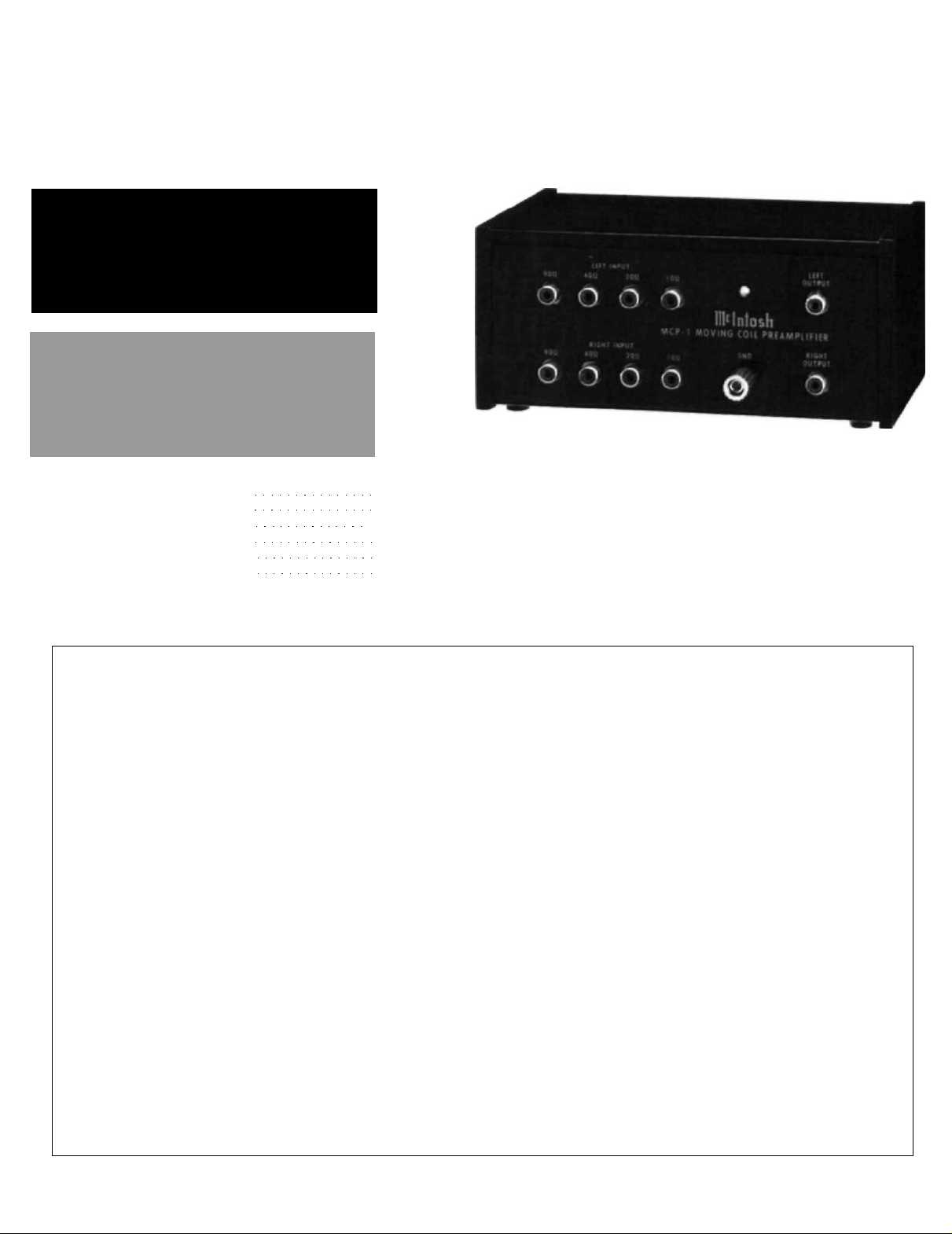
Connect the leads from your turntable to the proper impedance for your
cartridge on the MCP 1 input.
Connect the output of the MCP 1
head amplifier to the moving magnet
phono input on the preamplifier.
Connect the turntable ground to the
MCP 1 ground terminal.
Then, connect a ground wire between
the MCP 1 ground terminal and the
ground terminal on the preamplifier.
It is imperative that there be no ground loops
(multiple grounding paths) on the input and output
cables connecting the MCP 1. Each channel of the
MCP 1 has independent ground circuits. The input
cables from the tonearm must have separate
grounds for each channel and these grounds must
not connect to the turntable frame ground. The output cables from the MCP 1 should have independent
ground paths to the preamplifier. If you would like to,
you can test the grounding system using an ohm
meter. When testing the MCP 1 without any connections to other equipment, the ohm meter should
measure 200 ohms between the left and right channel grounds and 100 ohms from each channel
ground to the MCP 1 ground terminal.
2
Page 3

Performance Limits
And Ratings
Performance Limits
Performance limits are the maximum deviation
from perfection permitted for a Mcintosh instrument. We promise you that when you purchase a
new MCP 1 from a Mcintosh franchised dealer, it will
be capable of or can be made capable of performance at or exceeding these limits or you can return
the unit and get your money back. Mcintosh is the
only manufacturer that makes this statement.
INPUT IMPEDANCES—10, 20, 40 and 90 ohms
GAIN —10W - 31 dB, 20W - 26 dB, 400 - 20 dB, 90W - 13
dB
FREQUENCY RESPONSE— + 0, -0.5 dB, 20 Hz to
70 kHz
TOTAL HARMONIC DISTORTION —Less than .01%
SIGNAL TO NOISE RATIO—83 dBA (re: 500µV input
at 1 kHz, 10W input, with RIAA equalization)
(equivalent to - 149 dBV at input at 1 kHz).
PHASE SHIFT—Non inverting
CHANNEL SEPARATION —More than 90 dB, 20 Hz
to 20 kHz
GENERAL INFORMATION
SEMICONDUCTOR COMPLEMENT—
22 Bipolar Transistors
2 Integrated Circuits
11 Diodes
POWER REQUIREMENT—85-135 V, 50/60 Hz, 2 watts
MECHANICAL INFORMATION
Size—7 inches wide (17.8 cm) by 33/16 inches high (8.1
cm) by 5 inches deep (12.7 cm)
FINISH—Cabinet is rosewood finish on solid
macassar ebony. Front panel is black with gold
nomenclature. Chassis is black.
WEIGHT—3 pounds (1.4 kg) net, 5.5 pounds (2.5 kg)
in shipping carton
3
Page 4

How To Design A
Head Amp
The input transistors, input circuit configuration,
and the power supply required critical design consideration since noise and hum must be held to an
absolute minimum.
Transistor noise is characterized by two noise
components; en, Equivalent Short-circuit RMS Noise
Voltage, and in, Equivalent Open-circuit RMS Noise
Current. The resistance or impedance of the MC cartridge and resistance in the input circuit of the
amplifier also contribute Thermal Noise Voltage, er,
as a result of random electron movement within
these resistances. The combined noise voltage, en,
appearing at the input of the amplifier can be
calculated as:
The significance of this equation is that it tells us
the noise in a MC preamplifier is largely determined
by en, transistor noise voltage and not in, transistor
noise current, since R
transistor design. For a transistor to have low en it
must have low base diffusion resistance, rbb. This
requires that the transistor must have a large base
diffusion area with a long case perimeter and use a
low resistivity silicon material. Also, surface
leakage must be absolutely minimum.
The complementary input stage transistors in the
MCP 1 have these characteristics. The equivalent
rbb can be lowered further by parallelling a number
of transistors. Eight transistors are parallelled in the
MCP 1 which gives a reduction of 9 dB in noise level
over using just one transistor. This design ap-
proaches closely the theoretical optimum. To
guarantee performance each input transistor is in-
dividually tested for noise voltage and noise current
at 100 Hz, 1 kHz, and 10 kHz before it is mounted in
the MCP 1. This testing is time consuming but
assures noise free operation.
Each channel of amplification in the MCP 1 uses
two stages of amplification. The first stage has eight
low noise bipolar transistors in a parallel complementary push-pull configuration. This stage
amplifies the signal between 2.5 and 20 times (8 to
26 dB) depending on which input impedance is used.
The second stage uses a pair of complementary
bipolar transistors with a gain of 1.8 times (5 dB).
The over all amplifier is described as a noninverting
parallel cascaded complementary low noise bipolar
transistor amplifier circuit.
The two cascaded stages of amplification in the
is small. This dictates the
gen
MCP 1 preserve the phase of the input signal and in-
crease the signal handling ability or dynamic range.
The input stage inverts the signal and the second
stage restores the phase to zero. The inverting input
stage has an important additional noise advantage.
If the input is open circuited the noise output
reduces instead of increasing as in some other
designs.
The power supply circuit required a new approach
with very careful design. Many MC amplifiers use
batteries to avoid hum and noise problems. These
amplifiers, of course, require battery replacement
and usually the noise and distortion performance is
compromised to allow better battery life. The MCP 1
uses a line voltage power source to eliminate the
need to compromise its noise performance. But the
usual problem of a power transformer had to be solved first. Power transformers which use 50/60 Hz have
external magnetic fields which can modulate the
minute signal in the moving coil cartridge, add hum
and noise to the cartridge, to the cartridge connecting cable and even to the main preamplifier. The
design of the MCP 1 eliminates all of these problems. Knowing that a 50/60 Hz hum field simply
could not be tolerated the Mcintosh design group
chose a totally new approach. A high frequency,
completely shielded, solid state switch mode power
supply was used.
The AC power line feeds a reactive voltage divider
and a full wave bridge rectifier. The rectifier produces 24 volts DC which is filtered and supplied to a
15 volt series voltage regulator. This regulator has 70
dB ripple rejection and reduces the power line hum
to a negligible level. The 15 volts DC powers a stable
multivibrator/frequency divider with an output frequency of 200 kHz. The 200 kHz drives a push-pull
power switching amplifier followed by a ferrite core
toroidal transformer. This transformer has two
secondary windings bifilarly wound. Each winding
feeds a separate rectifier and filter system. The two
outputs are completely independent. One feeds the
left amplifier channel and the other feeds the right.
Filters and shielding are used to contain the 200 kHz
switching within the power supply itself and there is
no unwanted interference radiation or conduction.
The MCP 1 has three independent grounding
systems to prevent ground loops when connecting
input and output cables. The steel metal enclosure
connects to a ground post for grounding to the turn-
table frame and associated amplifying equipment.
The left and right channels have separate grounds.
There is no hum or noise introduced as a result of
the routing of input and output cables.
4
 Loading...