

Page 1

MCD751 Compact Disc Transport
OWNERS
MANUAL
MCD751
McIntosh Laboratory, Inc. 2 Chambers Street Binghamton, New York 13903-2699 Phone: 607-723-3512 FAX: 607-724-0549
Page 2

Thank You, Please Take A Moment,
Customer Service and Table of Contents
Thank You
Your decision to own this McIntosh MCD751 Compact
Disc Transport ranks you at the very top among discriminating music listeners. You now have The Best. The
McIntosh dedication to Quality, is assurance that you
will receive many years of musical enjoyment from this
unit.
Please take a short time to read the information in this
manual. We want you to be as familiar as possible with all
the features and functions of your new McIntosh.
Please Take A Moment
The serial number, purchase date and McIntosh dealer
name are important to you for possible insurance claim or
future service. The spaces below have been provided for
you to record that information:
Serial Number:
Purchase Date:
Dealer Name:
Technical Assistance
If at any time you have questions about your McIntosh
product, contact your McIntosh dealer who is familiar with
your McIntosh equipment and any other brands that may
be part of your system. If you or your dealer wish additional help concerning a suspected problem, you can receive technical assistance for all McIntosh products at:
McIntosh Sales Corporation
661 W. Redondo Beach Blvd.
Gardena, CA 90247
Phone: 888-979-3737
Fax: 310-217-9288
Customer Service
If it is determined that your McIntosh product is in need of
repair, you can return it to your dealer. You can also return
it to the McIntosh Laboratory Service Repair department.
For assistance on factory repair return procedure, contact
the McIntosh Repair Department at:
Table of Contents
Thank You.......................................................................... 2
Please Take a Moment ....................................................... 2
Technical Support .............................................................. 2
Customer Service............................................................... 2
Table of Contents............................................................... 2
Safety Instructions ............................................................. 3
Introduction ....................................................................... 4
Performance Features ........................................................ 4
Installation ......................................................................... 5
Rear Panel Connections and Switch .................................. 6
How to Connect the MCD751 ........................................... 7
Front Panel Controls, Displays, Push-Buttons,
and Switch ......................................................................... 8
How to Operate the MCD751............................................ 9
Remote Control Push-Buttons ......................................... 12
How to Operate by Remote Control ................................ 13
Specifications .................................................................. 14
Packing Instruction .......................................................... 15
NOTES:
1. The following Connecting Cable is available from the
McIntosh Parts Department:
Data and Power Control Cable Part No. 170-202
Six foot, shielded 2 conductor, with 1/8 inch stereo mini
phone plugs on each end.
2. For additional connection information, refer to the owners
manual(s) for any component(s) connected to the MCD751
Compact Disc Transport.
3. The MCD751 Laser Pickup assembly is protected from
shocks and movement during transit by a transport locking
mechanism. When the mechanism is in the LOCK position,
the MCD751 Disc Tray will still open or close, however, the
Laser assembly will not move and a disc will not play until
the Locking mechanism is moved to the FREE position.
Access the mechanism through a clearance hole in the
bottom panel of the player, near to the decal as illustrated
below and adjust the mechanism with the supplied tool or a
small screwdriver.
McIntosh Laboratory, Inc.
2 Chambers Street
Binghamton, New York 13903
Phone: 607-723-3515
Fax: 607-723-1917
Copyright 1999 by McIntosh Laboratory, Inc.
2
Decal
Supplied Tool
Page 3
IMPORTANT SAFETY
INSTRUCTIONS!
PLEASE READ THEM BEFORE
OPERATING THIS EQUIPMENT.
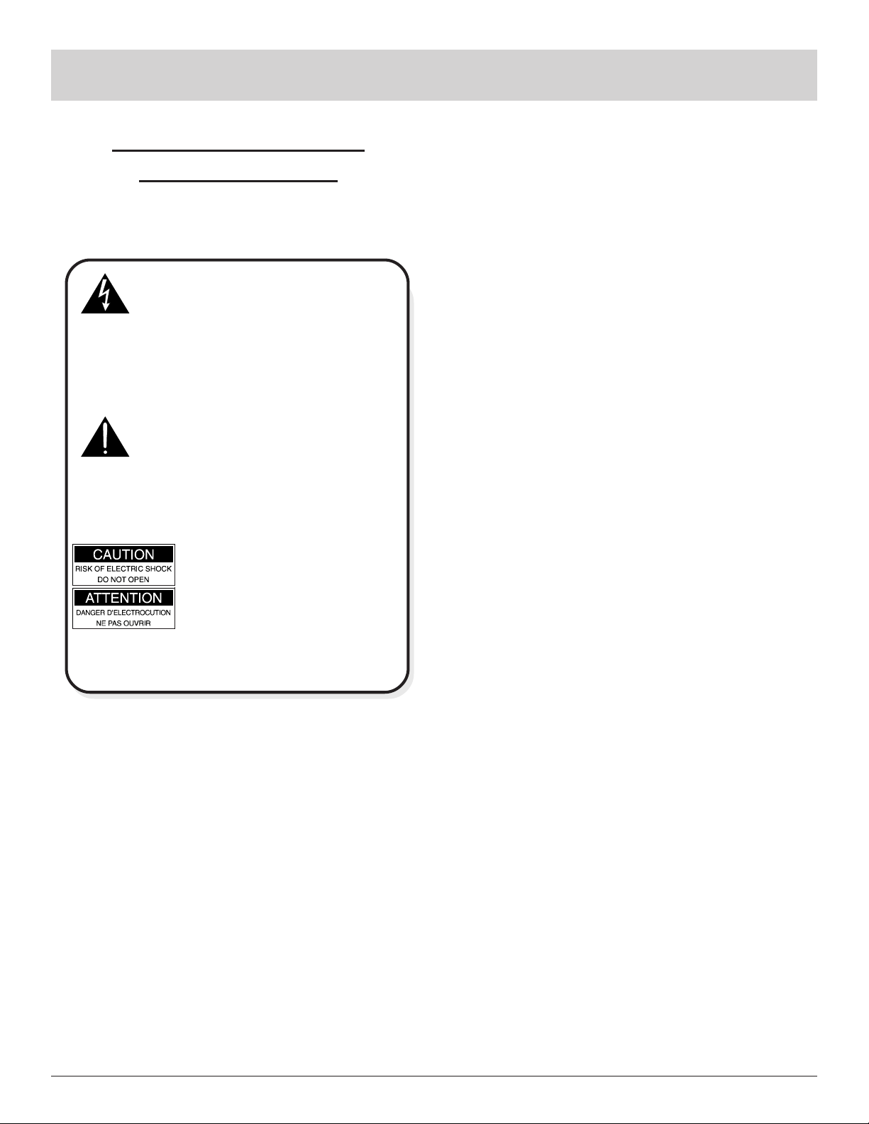
WARNING SHOCK HAZARD DO NOT OPEN.
The lightning flash with arrowhead, within an equilateral
triangle, is intended to alert the user to the presence of
uninsulated dangerous voltage within the products
enclosure that may be of sufficient magnitude to consti-
tute a risk of electric shock to persons
AVIS RISQUE DE CHOC NE PAS OUVRIR.
The exclamation point within an equilateral triangle is
intended to alert the user to the presence of important
operating and maintenance (servicing) instructions in
the literature accompanying the appliance.
NO USER-SERVICEABLE
PARTS INSIDE. REFER
SERVICING TO
QUALIFIED PERSONNEL
To prevent the risk of electric shock, do not remove
cover (or back). No user serviceable parts inside. Refer
servicing to qualified personnel.
General:
1. Read all the safety and operating instructions, contained in this owners manual, before operating this
equipment.
2. Retain this owners manual for future reference about
safety and operating instructions.
3. Adhere to all warnings and operating instructions.
4. Follow all operating and use instructions.
5. Warning: To reduce risk of fire or electrical shock,
do not expose this equipment to rain or moisture.
This unit is capable of producing high sound pressure levels. Continued exposure to high sound pressure levels can cause permanent hearing impairment or loss. User caution is advised and ear protection is recommended when playing at high volumes.
6. Caution: to prevent electrical shock do not use this
(polarized) plug with an extension cord, receptacle
or other outlet unless the blades can be fully inserted to prevent blade exposure.
.
Safety Instructions
Attention: pour pevenir les chocs elecriques pas
utiliser cette fiche polarisee avec un prolongateur,
une prise de courant ou un autre sortie de courant,
sauf si les lames peuvent etre inserees afond ans en
laisser aucune partie a decouvert.
7. For added protection for this product during a lightning
storm, or when it is left unattended and unused for long
periods of time, unplug it from the wall outlet. This
will prevent damage to the product due to lightning or
power line surges.
8. Do not use attachments not recommended in this
owners manual as they may cause hazards.
Installation:
9. Locate the equipment for proper ventilation. For example, the equipment should not be placed on a bed,
sofa, rug, or similar surface that may block ventilation
openings; or, placed in a built-in installation, such as a
bookcase or cabinet, that may impede the flow of air
through the ventilation openings.
10. Locate the equipment away from heat sources such as
radiators, heat registers, stoves, or other appliance (including amplifiers) that produce heat.
11. Mount the equipment in a wall or cabinet only as described in this owners manual.
12. Do not use this equipment near water; for example,
near a bathtub, washbowl, kitchen sink, laundry tub, in
a wet basement or near a swimming pool, etc.
13. Do not place this product on an unstable cart, stand,
tripod, bracket, or table. The equipment may fall, causing serious injury to a person, and serious damage to
the product.
Connection:
14. Connect this equipment only to the type of AC power
source as marked on the unit.
15. Route AC power cords so that they are not likely to be
walked on or pinched by items placed upon or against
them, paying particular attention to cords at plugs, convenience receptacles, and the point where they exit
from the instrument.
16. Do not defeat the inherent design features of the polarized plug. Non-polarized line cord adapters will defeat
the safety provided by the polarized AC plug. If the
plug should fail to fit, contact your electrician to replace your obsolete outlet. Do not defeat the safety
purpose of the grounding-type plug.
3
Page 4

Safety Instructions cont,
Introduction and Performance Features
17. Do not overload wall outlets, extension cords or integral convenience receptacles as this can result in a risk
of fire or electric shock.
Care of Equipment:
18. Clean the instrument by dusting with a dry cloth. Unplug this equipment from the wall outlet and clean the
panel with a cloth moistened with a window cleaner.
Do not use liquid cleaners or aerosol cleaners.
19. Do not permit objects of any kind to be pushed and/or
fall into the equipment through enclosure openings.
Never spill liquids into the equipment through enclosure openings.
20. Unplug the power cord from the AC power outlet
when left unused for a long period of time.
Repair of Equipment:
21. Unplug this equipment from the wall outlet and refer
servicing to a qualified service personnel under the following conditions:
A. The AC power cord or the plug has been damaged.
B. Objects have fallen, or liquid has been spilled into
the equipment.
C. The equipment has been exposed to rain or water.
D. The equipment does not operate normally by fol-
lowing the operating instructions contained within
this owners manual. Adjust only those controls
that are covered by the operating instructions, as an
improper adjustment of other controls may result
in damage and will often require extensive work by
a qualified technician to restore the product to its
normal operation.
E. The equipment has been dropped or damaged in any
way.
F. The equipment exhibits a distinct change in perfor-
mance - this indicates a need for service.
22. Do not attempt to service beyond that described in the
operating instructions. All other service should be referred to qualified service personnel.
23. When replacement parts are required, be sure the service technician has used replacement parts specified by
McIntosh or have the same characteristics as the original part. Unauthorized substitutions may result in fire,
electric shock, or other hazards.
24. Upon completion of any service or repairs to this product, ask the service technician to perform safety checks
to determine that the product is in proper operating
condition.
Introduction
The new McIntosh MCD751 Compact Disc Transport offers the latest concepts in mechanical excellence for precise CD reproduction. Combine the MCD751 with a McIntosh MDA700 D/A Converter, Decoder or Control Center
with a digital input and you will enjoy reproduction of your
favorite Compact Discs with unparalleled sonic beauty and
accuracy.
Performance Features
· Precision Transport Mechanism
Included is a Vibration-Free Rigid Disc Clamping System
consisting of a CD size die-cast, high density aluminum
overhead turntable with a high precision helicoid clamp.
The motor bridge and clamping system are made of high
molecular material containing polyester fibers and ceramic
powders.
· Digital Servo Control Motors
The Brushless Hall Effect Drive Spindle Motor for disc rotation coupled with the Linear Laser Assembly Motor together helps boost clarity and maintain exacting levels of
digital sound reproduction.
· Remote Control
The Remote Control is included that will allow complete
control of major functions.
· Remote Power and Data Control
Remote Power Control In/Out allows the MCD751 to turn
on/off with a McIntosh Control Center. The Data In/Out for
remote control operation from another McIntosh component.
· Special Power Supply
A fully regulated power supply with a special power transformer ensures stable noise free operation even though the
power line should vary.
4
Page 5

Installation
The MCD751 can be placed upright on a table or shelf,
standing on its four feet. It also can be custom installed in a
piece of furniture or cabinet of your choice. The required
panel cutout, ventilation cutout and unit dimensions are
shown.
Always provide adequate ventilation for your MCD751.
Cool operation ensures the longest possible operating life
for any electronic instrument. Do not install the MCD751
directly above a heat generating component such as a high
powered amplifier. If all the components are installed in a
single cabinet, a quiet running ventilation fan can be a defi-
Front View of the MCD751
custom installed
End Caps
5-3/8"
136.9mm
Installation
nite asset in maintaining all the system components at the
coolest possible operating temperature.
A custom cabinet installation should provide the following minimum spacing dimensions for cool operation. Allow
at least 2 inches (5.1cm) above the unit and 1 inch
(2.54cm) on each side of the control center, so that airflow
is not obstructed. Allow 16 inches (40.64cm) depth behind
the mounting panel, which includes clearance for connectors. Allow 3/4 inch (1.9cm) in front of the mounting panel
for clearance. Be sure to cut out a ventilation hole in the
mounting shelf according to the dimensions in the drawing.
17-1/2"
444mm
7/32"
5.3mm
4-7/8"
123.8mm
1/4"
6mm
Panel Height
5-5/16"
134.9mm
17-1/16"
433.4mm
Outline of Front Panel
Edge of Cutout
(Front View)
Side View of the MCD751
custom installed
Bottom View of the MCD751
custom installed
Mounting Surface
Mounting Surface
Bottom of Cutout
and Top of Support
Shelf Must Coincide
(Side View)
6"
3/16"
5.1mm
Outline of Unit
Support Shelf
15"
Cut Out Center
for Ventilation
(Bottom View)
9"
Support Shelf
Mounting Bracket at Both Sides of the Rear Panel.
Fasten with 6-32 x 3/8 Machine Scr ew and Washer to Chassis.
Fasten with 6 x 1/2 Wood Screw and Washer to Support Shelf.
5
Page 6

MCD751 Rear Panel Connections
MCD751 Rear Panel
Connections
POWER CONTROL IN receives turn on signals from a
McIntosh component and
POWER CONTROL OUT
sends turn on signals on to another McIntosh Component
DATA IN receives operating
data from a McIntosh Control
Center or D/A Converter and
DATA OUT sends operating
data to a McIntosh component
DIGITAL COAXIAL
OUTPUT send signals to
an external D/A Converter or Control Center
with a D/A Converter
DIGITAL OPTICAL
OUTPUT send signals to
an external D/A Converter
or Control Center with a
D/A Converter
Connect the MCD751 power
cord to a live AC outlet. Refer
to information on the back
panel of your MCD751 to determine the correct voltage for
your unit
6
Page 7

How to Connect the MCD751
1. Connect the MCD751 power cord to a live AC outlet.
2. Connect a Power Control Cable from the POWER
CONTROL OUT of a McIntosh MDA700 D/A Converter or Control Center to the MCD751 POWER
CONTROL IN.
3. Connect a Data Cable from the MCD751 DATA IN
Jack to a DATA OUT Jack on a McIntosh MDA700 D/
A Converter or Control Center.
4. Remove the protective cap from the MCD751 OPTICAL DIGITAL OUT connector.
How to Connect the MCD751
5. Connect an Optical Cable from the MCD751 OPTICAL DIGITAL OUT to the OPTICAL DIGITAL INPUT of a McIntosh MDA700 D/A Converter, Decoder
or Control Center.
Note: An optional connecting method is to use a coaxial cable
from the MCD751 Coaxial Output to the Coaxial
Digital Input of a McIntosh MDA700 D/A Converter,
Decoder or Control Center.
McIntosh Control Center
To AC Outlet
McIntosh D/A Converter
7
Page 8

MCD751 Front Panel Display, Push-Buttons
and Switch
MCD751 Front Panel Display,
Push-Buttons and Switch
Indicates when the disc tray
is opening or closing and
when a disc is in the tray
Indicates when the
Pause Mode is active
Disc Tray opens to load
and unload a disc
Standby Power
On Indicator
IR Sensor receives
commands from a
remote control
Opens the disc
tray for loading
or unloading
discs
8
Stops disc
play
Use to pause
during play
Starts disc play
Indicates Time, Track
and different Modes of
Operation
Move rapidly
backward
through a disc
during play
Move rapidly
forward
through a disc
during play
Move back
one track at
a time
POWER
switch turns
all AC power
completely
ON or OFF
Move forward
one track at a
time
Page 9

How to Operate the MCD751
Power On
The MCD751 can be turned on manually with the front
panel POWER SWITCH. When a Power Control cable is
connected to a McIntosh DA Converter or Control Center,
the MCD751 POWER SWITCH can be left on, and the
player will turn on automatically whenever the other component turns on. Refer to front panel drawing on the opposite page.
How to Operate the MCD751
Pause Play
1. Open the tray and load a disc.
2. Press the PAUSE pushbutton.
3. The tray will close, the player will enter Pause Mode.
4. When the Track Time Display appears and indicates
(0m 00s), the player will be ready to immediately start
playing Track 1 when either the PAUSE or PLAY
pushbutton is pressed.
How to Load a Disc
1. Press the OPEN/CLOSE pushbutton. The Red LED
above the pushbutton will start flashing and the disc
tray will slide out.
The front panel
display will indicate OPEN. Refer to Figure 1.
Figure 1
2. Place a disc within the guides, on the tray with the label facing up.
Note: There is a recessed area on the disc tray to
accommodate 3 inch (7.6cm) mini discs.
3. Press the OPEN/CLOSE pushbutton a second time.
The Red LED above the pushbutton will start flashing,
the display will indicate CLOS and the disc tray will
close. The LED
will stop flashing
and stay on as
long as a disc is in
Figure 2
the tray or playing. Refer to Figure 2. After the disc
tray closes, for a few seconds the Time display will indicate the total
number of tracks
and total play
time of the disc
Figure 3
just inserted. Refer to Figure 3.
Disc Play Modes
Listed below are six different modes for playing all or part
of a Compact Disc:
Standard Play
1. Press the PLAY pushbutton and play will start from the
first track on the disc.
Note: After a disc is inserted in the tray, you can also press
just the Play pushbutton to both close the disc tray and
start playing the disc.
Direct Access Play
1. Open the disc tray and load a disc.
2. Press a NUMBER pushbutton on the Remote Control
corresponding to the desired disc track.
3. The disc tray will close and play will start from the
specified track without need for pressing PLAY.
4. For track numbers above 9, press the +10 pushbutton
first and then required number. The +10 pushbutton
must be pressed once for each multiple of ten track
numbers. For example, for track number 25, press +10
twice and then 5.
Single Track Play
1. Press the SINGLE pushbutton on the Remote. The
Single Indicator
on the front
panel display
will light. Refer
Figure 4
to Figure 4.
2. Press the NUMBER pushbutton(s) on the Remote that
corresponds to the desired disc track you wish to play.
3. The selected track will play once, and then the
MCD751 will Stop.
4. To play another single track, repeat Step 2.
5. To cancel the Single Mode, press the SINGLE
pushbutton again.
Preselected Track Play
Up to 20 specific tracks on a disc can be selected to play in
any desired order.
1. Load a disc in the player.
2. Press the PGM pushbutton on the Remote. Refer to
Figure 5.
3. Press the NUMBER
pushbutton(s)
Figure 5
on the Remote
to select the desired track(s) to play.
9
Page 10

How to Operate the MCD751, cont
How to Operate the MCD751,
cont
4. If you wish to change a selection, press the CLEAR
pushbutton and then the number for the new track selection.
5. Press the REVIEW pushbutton to review the details of
each track selected for playback.
6. Press the PLAY pushbutton and each of the tracks will
play in the order you selected.
Note: Track selection is performed when the player is in Stop
Mode. The track selection memory will be retained
when all tracks have played or when the STOP
pushbutton is pressed. To cancel the track selection
memory, press the STOP pushbutton twice, press the
PGM pushbutton or open and close the disc tray.
Delete Play
You can delete any tracks on a disc that you do not wish to
listen to.
1. Load a disc into the tray.
2. Press the DELETE pushbutton. Refer to Figure 6.
3. Press the
NUMBER
pushbutton (s)
on the Remote
Figure 6
to select the
tracks you wish to delete.
4. If you wish to change a selection, press the CLEAR
pushbutton and then the number for the new track selection to delete.
5. Press the REVIEW pushbutton to view the details of
each track selected to delete.
6. Press the PLAY pushbutton and all the tracks except
the ones deleted will play.
7. Cancel the Delete function by pressing the DELETE
pushbutton a second time, pressing the STOP
pushbutton or open and then close the disc tray.
Pause Mode
1. Press the PAUSE pushbutton to temporarily stop play
operation at any time. The Red LED above the PAUSE
pushbutton will light. Refer to Figure 7.
2. Press the PAUSE pushbutton a second time to resume
playing the disc.
Stop Mode
Press the STOP pushbutton at any time to stop disc play.
Index Search Mode
The INDEX pushbuttons allow direct access to any index
point encoded in a disc track.
1. Press either a LEFT(lower number) or RIGHT(higher
number) INDEX pushbutton to select a desired Index
Number in a
specific disc
track. Refer to
Figure 8.
Figure 8
2. The disc will
automatically start playing from the selected Index
Point.
Note: The Index Numbers appear to the right of the Track
Numbers in the Display Panel. Not all discs will have
Index Numbers.
Reverse or Fast Forward
Press REV or FF pushbuttons to move rapidly through all
tracks on a disc. Speeded up sound will be audible during
this operation.
10
Figure 7
Page 11

How to Operate the MCD751, cont
How to Operate the MCD751,
cont
Back and Next
Press BACK or NEXT pushbuttons to jump from the beginning of one track to another. This operation can be performed in either Stop or Play Mode. If a track is playing,
pressing BACK once, and play will restart at the beginning
of the track that is playing. Pressing BACK twice will
move back to the start of the previous track and start playing.
Note: BACK and NEXT can be performed when the disc is
playing, or in the Stop Mode.
Repeat Functions
The repeat function allows repeat play of an entire disc, a
single track, a preselected track, a disc with deleted tracks
or a portion of a disc determined by a start and stop point.
Note: Press the REPEAT pushbutton to activate Repeat
function in Delete Play, Single Track Play and
Preselected Track Play Modes.
Repeat an entire disc
1. Press the REPEAT pushbutton. Refer to Figure 9.
2. Press the PLAY
pushbutton. The
entire disc will
play to the end,
Figure 9
start over and
continue playing repeatedly.
Note: The Repeat Mode can be engaged at any time during the
playing of a disc.
3. Cancel the entire disc Repeat Play Mode by pressing
the REPEAT pushbutton a second time.
Repeat play between two points
1. Load a disc and start it playing.
2. When the point on the disc that you wish to start Repeat Play is reached, (Point A), press the A-B
pushbutton. This sets the beginning of the disc segment
you wish to play repeatedly. The disc will continue to
play. Refer to
figure 10.
3. When the point
on the disc is
Figure 10
reached where you want Repeat Play to end, (Point B),
press the A-B pushbutton a second time. This sets the
ending of the disc segment you wish to play repeatedly.
This disc segment will now start to play repeatedly.
4. Cancel A-B play mode by pressing A-B again or
pressing Stop.
Time Display
1. When the Disc is loaded and the tray closes, the total
number of tracks and total disc time are displayed for
a few seconds. Refer to Figure 11.
Note: When the
player is in
Stop Mode,
press the
TIME
pushbutton once to display for a few seconds the total
number of tracks and total disc time.
Figure 11
2. When disc play starts, the elapsed time of each track
is indicated.
3. Press the Remote Control TIME pushbutton once and
the remaining
track time is
displayed. Refer to Figure
12.
Figure 12
4. Press the Remote Control TIME pushbutton a second
time and the
total remaining
time on the
disc is displayed. Refer
Figure 13
to Figure 13.
Reset of Microprocessors
In the event that the MCD751 stops functioning, turn the
POWER SWITCH OFF for approximately 10 Seconds.
This will reset the transport microprocessors. Refer to figure 7.
11
Page 12

Remote Control Push-Buttons
Use to review each
preselected or deleted
disc track
Remote Control Push-Buttons
Select disc tracks or any
numbered operation
Use to delete specific disc tracks
from playing
Use to preselect up
to 20 specific disc
tracks for playback
Use with number
pushbuttons to select
and play just a single
track
Use to play a
selected track or
a complete disc
repeatedly
Press to move
rapidly forward
or backward on
a disc
Use to clear a
preselected track
Use together with a
number pushbutton
to select track numbers higher than 10
Use in conjunction with
number pushbuttons to
select inputs on an
MDA700 D/A Converter
Selects front panel disc
time display mode
Selects a start and
stop time on a disc
with continuous repeatable playback
Use to jump back and
forth between disc tracks
12
Press to stop
disc playback
Use to pause and then
resume disc playback
Press to start
disc playback
Selects index numbers
on a track
Page 13

How to Operate the Remote Control
Numbered and +10 Pushbuttons
Press 1 through 9 to directly access these disc tracks. For
track numbers above 9, press the +10 pushbutton first and
then required number. The +10 pushbutton must be pressed
once for each multiple of ten track numbers. For example,
for track number 25, press +10 twice and then 5.
How to Operate the Remote Control
Index
Press either an LEFT(lower number) or RIGHT(higher
number) INDEX pushbutton to select a desired Index
Number in a specific disc track. The disc will start to play
from the selected index number. Not all discs have Index
numbers.
PGM
Press PGM and then the number(s) for all the specific
tracks you wish to select to play in any random order.
Clear
Press CLEAR to erase a selected track and replace with
another track.
Review
Press REVIEW to show on the display the details of the
first track selected to play in random order or a track deleted from playback. Each time the REVIEW pushbutton is
pressed, the display will show the details of the next track
selected or deleted.
Delete
Press DELETE and then one or more NUMBER
pushbutton(s) to delete tracks on a disc that you do not
want to play. Cancel the Delete function by pressing DELETE again or the STOP pushbutton.
Single
Press SINGLE and a specific number pushbutton (s) to select and play a single track.
Stop
Press the STOP pushbutton to stop the disc playing.
Note: The MCD751 Remote Control can also be used in a
remote area of any McIntosh remote control system to
operate the player by sending control signals to
McIntosh keypad or IR sensor. All the MCD751 Remote
Control pushbuttons are active in this configuration.
Alternate Remote Control Pushbutton Functions
Most basic MCD751 operating functions can be performed
with Remote Controls of other McIntosh products. Additional MCD751 functions can be performed with other Remote Controls by using pushbuttons that are labeled differently from the player Remote. The chart below lists the
MCD751 operations that can be performed by these different pushbuttons on Remote Controls of other McIntosh
products.
MCD751 Function Alternate Remote Pushbutton
+10 Review
REVerse Seek Down
FF (Fast Forward) Seek Up
Pause E (Enter)
MDA700 Function Alternate Remote Pushbutton
Input AM
Time
Press TIME to select the time display of elapsed track time,
remaining track time or total disc remaining time.
Input
Use together with NUMBER pushbuttons to select inputs
on an MDA700 D/A Converter.
Pause
Press the PAUSE pushbutton to momentarily stop play operation at any time. Press the PAUSE pushbutton a second
time to resume playing the disc.
13
Page 14

Specifications
Digital Output
Optical: -15dbm to -21dbm*
Coaxial: 0.5V p-p/75 ohm*
*Digital Audio Format, IEC958, S/P DIF
Transport
Pickup: Optical 3-beam laser
Objective Lens Drive System: 2-Dimentional parallel
Laser Type: GaAIAs semiconductor
Laser Beam Wavelenght: 780nm
Digital Signal Format
Sampling Frequency: 44.1KHz
Quantizaton Bit: 16-bit linear/channel
Bit Rate: 4.3218Mb/sec
Modulation Code: Eight to Fourteen Modulation
Error Correction: Cross Interleave Reed Solomon
Specifications
Power Requirements
100 Volts, 50/60Hz at 20 watts
110 Volts, 50/60Hz at 20 watts
120 Volts, 50/60Hz at 20 watts
220 Volts, 50/60Hz at 20 watts
230 Volts, 50/60Hz at 20 watts
240 Volts, 50/60Hz at 20 watts
Note: Refer to the rear panel of the MCD751 for the correct
voltage.
Dimensions
Front Panel:17-1/2 inches (44.5cm) wide, 5-3/8 inches
(13.7cm) high, depth behind front mounting panel is 15
inches (38.1cm) including clearance for connectors. Panel
clearance required in front of mounting panel is 3/4 inch
(1.9cm).
Note: When the CD tray is opened, the panel clearance
required in front of mounting panel is 6-3/4 inches
(17.2cm).
14
Page 15

Packing Instructions
Packing Instructions
In the event it is necessary to repack the equipment for shipment, the equipment must be packed exactly as shown below. It is very important that the four plastic feet are attached to the bottom of the equipment. This will ensure the
proper equipment location on the bottom pad. Failure to do
this will result in shipping damage.
Use the original shipping carton and interior parts only if
they are all in good serviceable condition. If a shipping carton or any of the interior part(s) are needed, please call or
write Customer Service Department of McIntosh Laboratory. Please see the Part List for the correct part numbers.
Quantity Part Number Description
1 034075 Shipping carton only
4 033837 Foam end cap
1 034076 Inside carton only
1 033726 Top pad
1 034036 Bottom pad
1 034077 Inner carton pad
4 017218 Plastic foot
4 100159 #10-32 x 3/4 screw
4 104083 #10 x 7/16 Flat washer
1 049270 Shipping carton complete with
all the above parts
15
Page 16

McIntosh Laboratory, Inc.
2 Chambers Street
Binghamton, NY 13903
McIntosh Part No. 040624
 Loading...