

Page 1
COMPACT DISC
CHANGER
CONTENTS
Performance Specifications ....................................... 2
Notes ......................................................................... 2
Rear View and Section Location ................................. 3
Block Diagram ........................................................... 4
Interconnection Diagram ........................................... 5
SERVICE MANUAL
Audio/Power Schematic and PCB ........................ 7 - 12
Display Schematic and PCB ................................ 13 -16
Parts List ............................................................ 17 - 18
Exploded View and Parts Lists ........................... 19 - 20
Repacking Instructions ............................................. 21
Page 2

PERFORMANCE SPECIFICATIONS
Frequency Response
+0, -0.5dB from 5Hz to 20,000Hz
Signal T o Noise Ratio
108dB (IHF A-weighted)
Dynamic Range
100dB
Harmonic Distortion
0.002%
Channel Separation
105dB
Maximum Output Level
2.0Vrms Balanced
2.0Vrms Unbalanced
Output Impedance
600 ohms Balanced
600 ohms Unbalanced
Sampling Frequency
44,100Hz
D/A Converter
24-bit dual converters with 8 times over sampling digital
filter
Error Correction
CIRC
Quantization
16-bit linear
T ransport Signal Readout T ype
Semiconductor Optical Laser
Disc Rotational V elocity
200 to 500rpm (constant linear velocity)
Wow and Flutter
Below current measurement limits
Power Requirements
100 Volts, 50/60Hz at 25 watts
110 Volts, 50/60Hz at 25 watts
120 Volts, 50/60Hz at 25 watts
220 Volts, 50/60Hz at 25 watts
230 Volts, 50/60Hz at 25 watts
240 Volts, 50/60Hz at 25 watts
Note: Refer to the rear panel of the MCD205 for the
correct voltage.
Dimensions
Front Panel: 17-1/2 inches (44.5cm) wide, 5-3/8
inches (13.7cm) high. Depth behind front
mounting panel is 15 inches (38.1cm) including
clearance for connectors. Panel clearance required
in front of mounting panel is 3/4 inch (1.9cm).
Note: When a CD Disc is inserted or ejected,
the panel clearance required in front
of mounting panel is 3-3/4 inches (9.5cm).
Weight
21 pounds (9.5kg) net, 35 pounds (15.9kg) in
shipping carton
Digital Output
Optical: -15dBm to –21dBm
Coaxial: 0.5v p-p/75 ohm
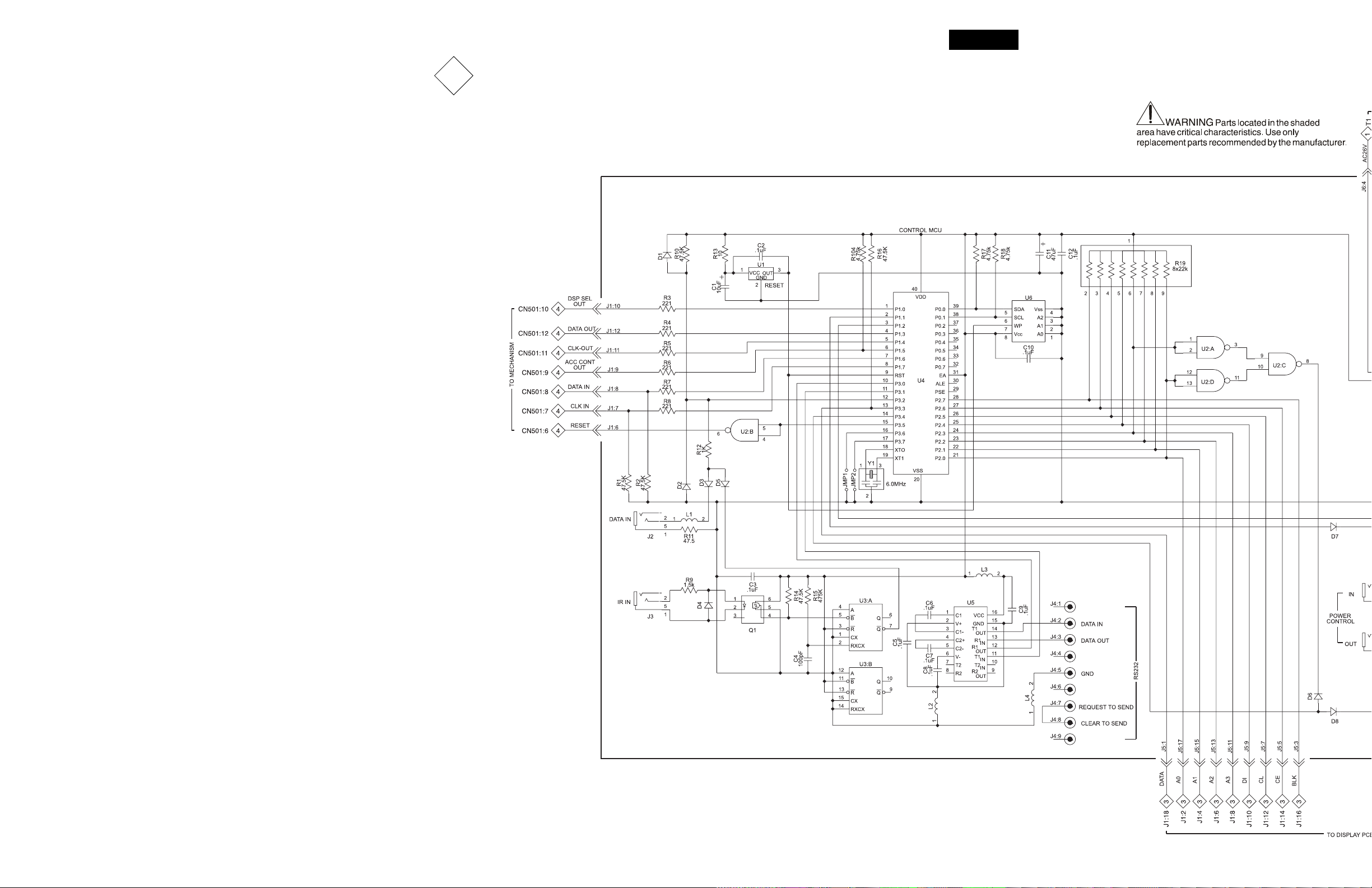
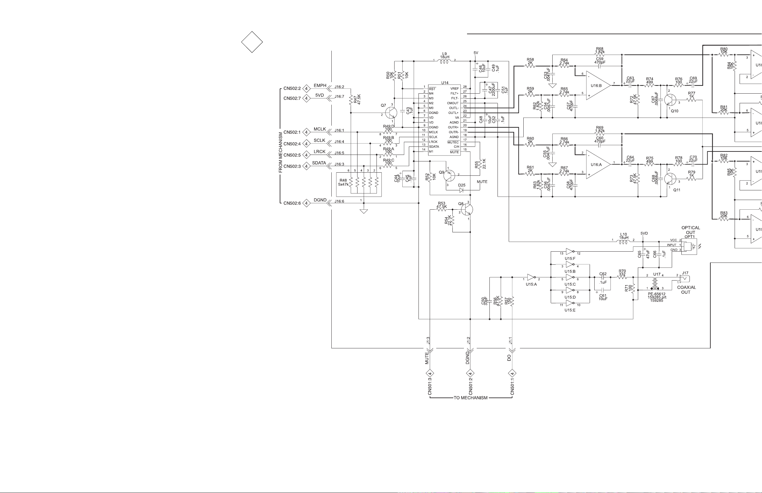
1. The heavy notes on the schematic denote the primary
signal path.
2. Unless otherwise noted, all voltages indicated on the
schematics are measured under the following conditions:
a. AC input at 120 volts, 50/60Hz.
b. All voltages are +/-10% with respect to ground. A
high impedance (10 megaohm) voltmeter must be used.
3. Unless otherwise specified:
a. Resistor values are in ohms.
b. Capacitor values are microfarads (uF).
c. Inductor values are in microhenries (uH).
NOTES
4. On PC board drawings, Square pad indicates:
a. Polarized Capacitors - Positive
b. Diodes - Cathode
c. Others - Pin 1
5. WARNING
Parts marked with the symbol have critical
characteristics. Use only replacement parts recommended by the manufacturer.
MusicBankTM is a registered trademark of the Nakamichi Corporation
2
Page 3
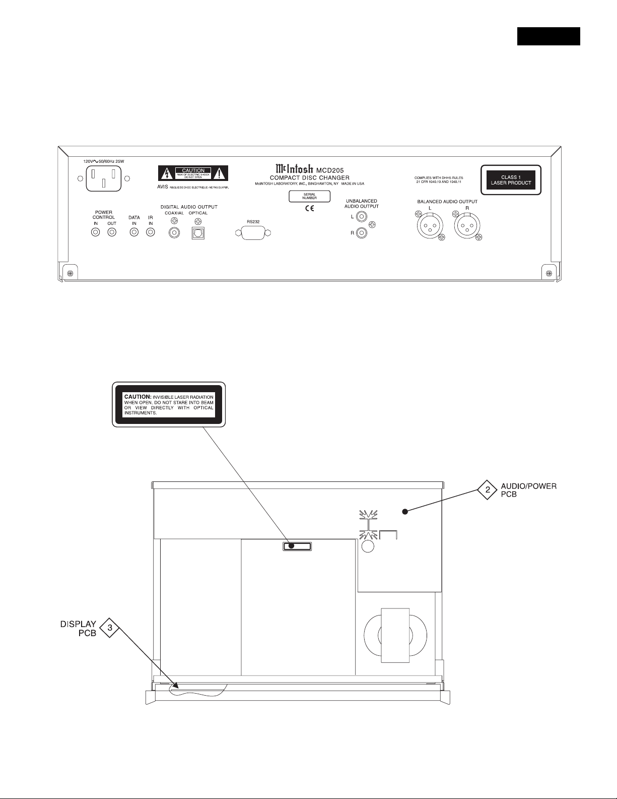
REAR VIEW
MCD205
SECTION LOCATION
TOP VIEW WITH COVER REMOVED
3
Page 4
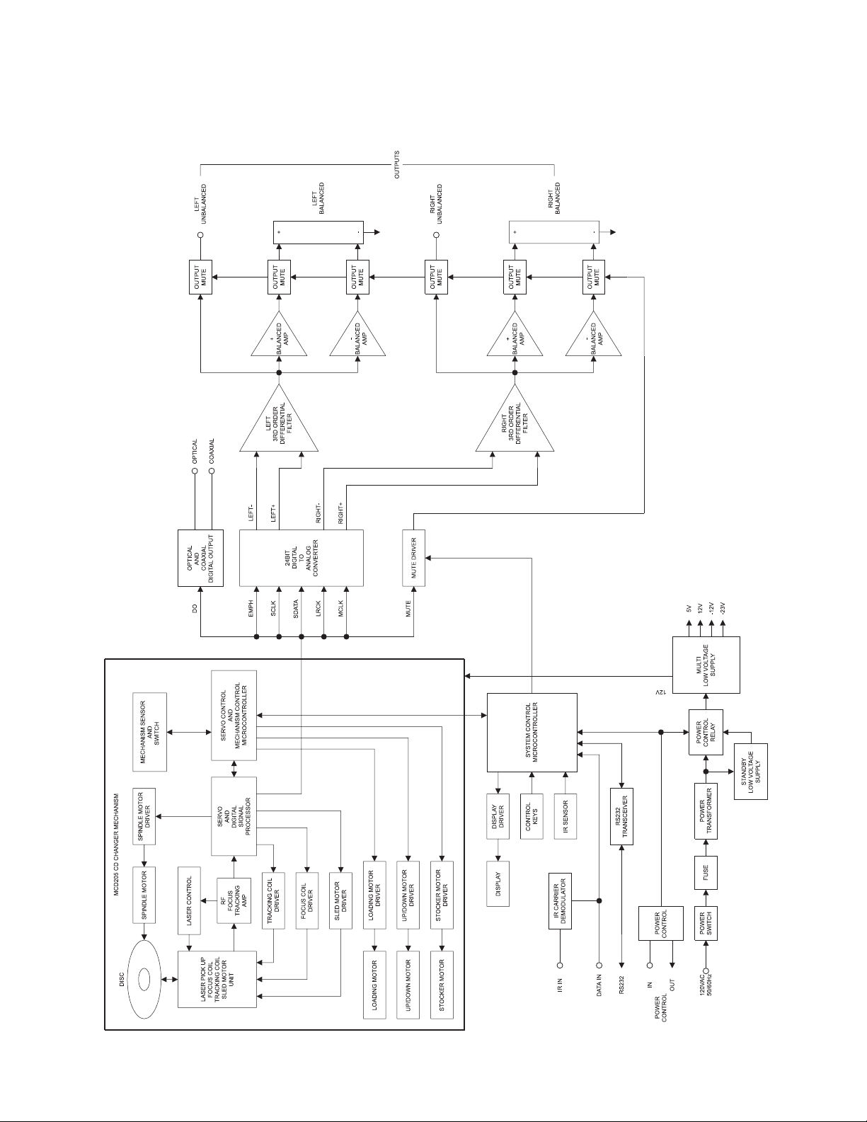
BLOCK DIAGRAM
4
Page 5
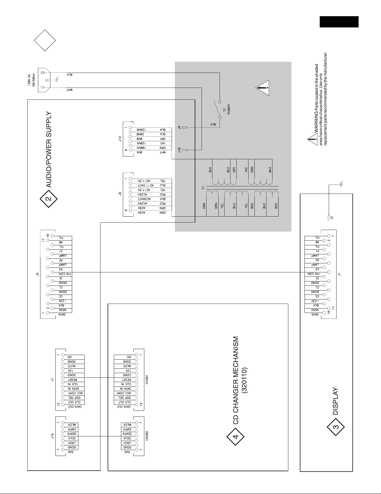
MCD205
1
INTERCONNECT
5
Page 6

NOTES
6
Page 7
MCD205
2
AUDIO/POWER 049730 SH 1 OF 2
7 8
Page 8

98
Page 9
2
AUDIO/POWER 049730 SH 2 OF 2
10 11
Page 10

121
Page 11
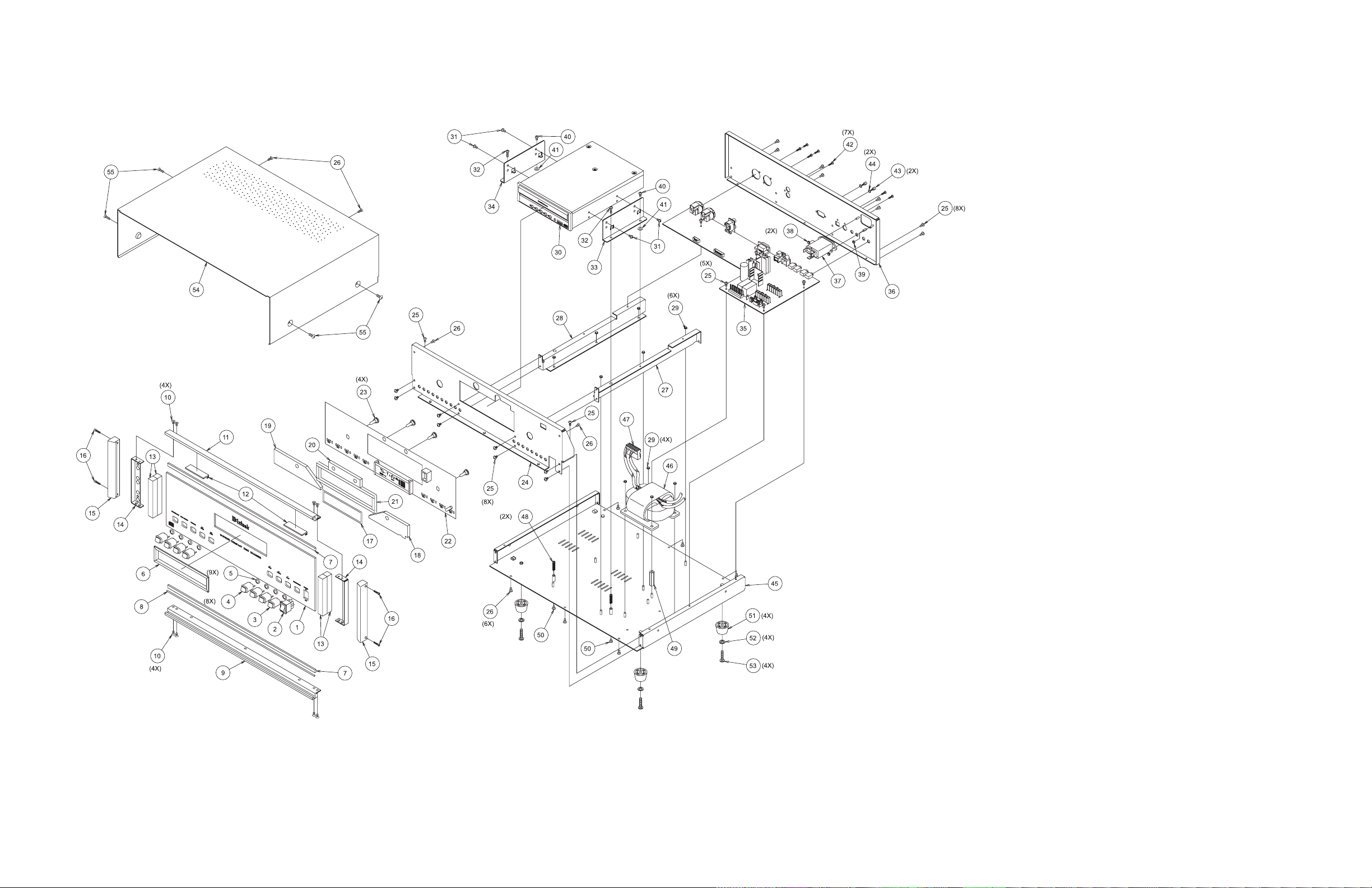
EXPLODED VIEW and PARTS LIST
Ref
No.
1 016468 GLASS
2 148073 SWITCH DPDT ROCKER
3 017531 PUSHBUTTON ASSY RED
4 017517 PUSHBUTTON ASSY BLK
5 078033 O-RING
6 017879 BEZEL GLASS
7 094016 TAPE FOAM 1/4 X 1/8
8 098113 CORD DIAL .027 BLACK BRAID SILK
9 018588 EXTRUSION BOTTOM
10 100147 SCREW MACHINE 6-32 X 3/16 PHIL
11 018585 EXTRUSION TOP
12 017798 GUIDES PRINTED CIRCUIT
13 094360 TAPE FOAM 1/2 X 1/2
14 005090 BRACKET EXTRUSION
15 018611 ENDCAP 5”
16 101042 SCREW TS 4-40 X 1/2 SLOT FILLISTER
17 092419 FILTER DISPLAY
18 017885 PLEXIGLAS DISPLAY RIGHT
19 017892 PLEXIGLAS DISPLAY LEFT
20 017886 PLEXIGLAS LOGO
21 094017 TAPE FOAM 1/4 X 1/4
22 049731 ASSY PCB DISPLAY
23 058153 LAMP INCANDESCENT
24 005224 SUBPANEL
25 101196 SCREW TAP SEMS 6-32 X 1/4 PH PN
26 101054 SCREW TAPTITE 6-32 X 1/4 PH PN
27 005222 ZEE BRACKET RIGHT
28 005223 ZEE BRACKET LEFT
29 102003 NUT MACHINE 6-32 W/LOCK
30 320110 5 DISC CD CHANGER
31 310330 METRIC SCREWS MCD205 CHANGER
32 100300 SCREW MACH SEMS 6-32 X 1 PH PN
33 005228 BRACKET MOUNTING RIGHT
34 005229 BRACKET MOUNTING LEFT
35 049730 ASSY PCB AUDIO-POWER
36 005227 REAR PANEL
37 117755 RECEPTACLE INPUT & LINE FILTER
38 102001 NUT KEP 4-40 CADMIUM PLATE
39 102020 NUT 6-32 SELF-LOCK
40 100271 SCREW SEMS 6-32 X 1/4 PH PN
41 104005 WASHER FLAT STEEL 6 X 3/8 X .032
42 101197 SCREW HI/LO 4-24 X 3/8 PH RD BLK
43 112015 STANDOFF
44 104142 WASHER LOCK 2.5mm INT STAR ZINC
45 005226 CHASSIS
46 159334 TRANSFORMER R-CORE POWER
47 117800 MTA CONNECTOR 8 PIN .156
48 019058 SPRING
49 112083 STANDOFF 6-32 X 1.250
50 100180 SCREW 6-32 X 1/8 PH PN
51 017218 FOOT PLASTIC BLACK
52 104083 WASHER #10 PLATED
53 100159 SCREW MACH 10-32 X 3/4 PH PN BLK
54 005102 COVER TOP
55 101078 SCREW TAP 8-32 X 5/16 PH PN BLK
Part
No.
Description
19 20
Page 12

REPACKING INSTRUCTION
MCD205
21
Page 13

COMPACT DISC CHANGER
SERVICE MANUAL
The continuous improvement of its products is the policy of McIntosh Laboratory Incorporated, who reserve the right to improve design without
notice. Because of the constant upgrading of McIntosh products’ circuitry and components, the Company cannot insure, and does not warrant, the
accuracy of the within schematic material, which is intended for information only.
McINTOSH LABORATORY, INC., 2 CHAMBERS STREET, BINGHAMTON, NEW YORK 13903 Printed in U.S.A. Part Number 040834
 Loading...