

Page 1
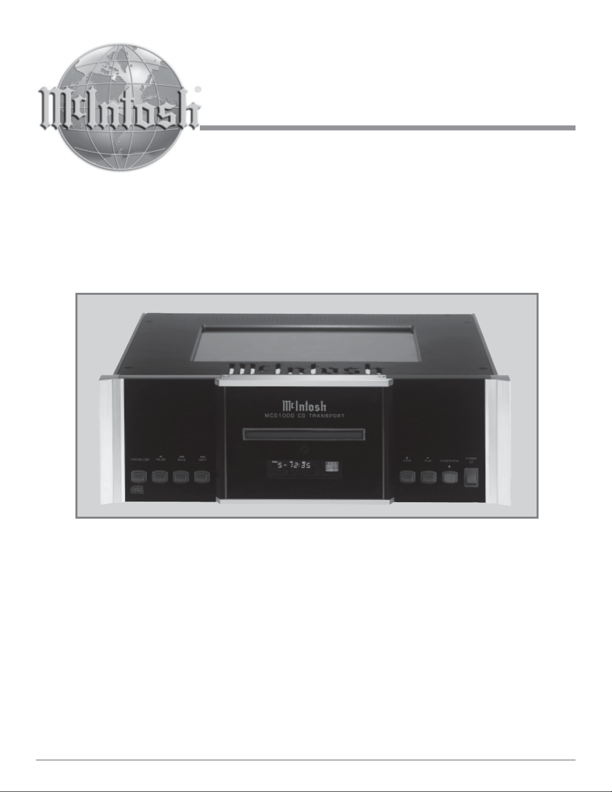
CD Transport
MCD1000
Owner ’s Manual
McIntosh Laboratory, Inc. 2 Chambers S treet Binghamton, New York 13903-2699 Phone: 607-723-3512 F AX: 607-724-0549
Page 2
The lightning flash with arrowhead, within
an equilateral triangle, is intended to alert
the user to the presence of uninsulated
“dangerous voltage” within the product’s
enclosure that may be of sufficient magnitude to constitute a risk of electric
shock to persons.
The exclamation point within an equilateral triangle is intended to alert the
user to the presence of important operating and maintenance (servicing)
instructions in the literature accompanying the appliance.
W ARNING - TO REDUCE RISK OF
FIRE OR ELECTRICAL SHOCK, DO
NOT EXPOSE THIS EQUIPMENT TO
RAIN OR MOISTURE.
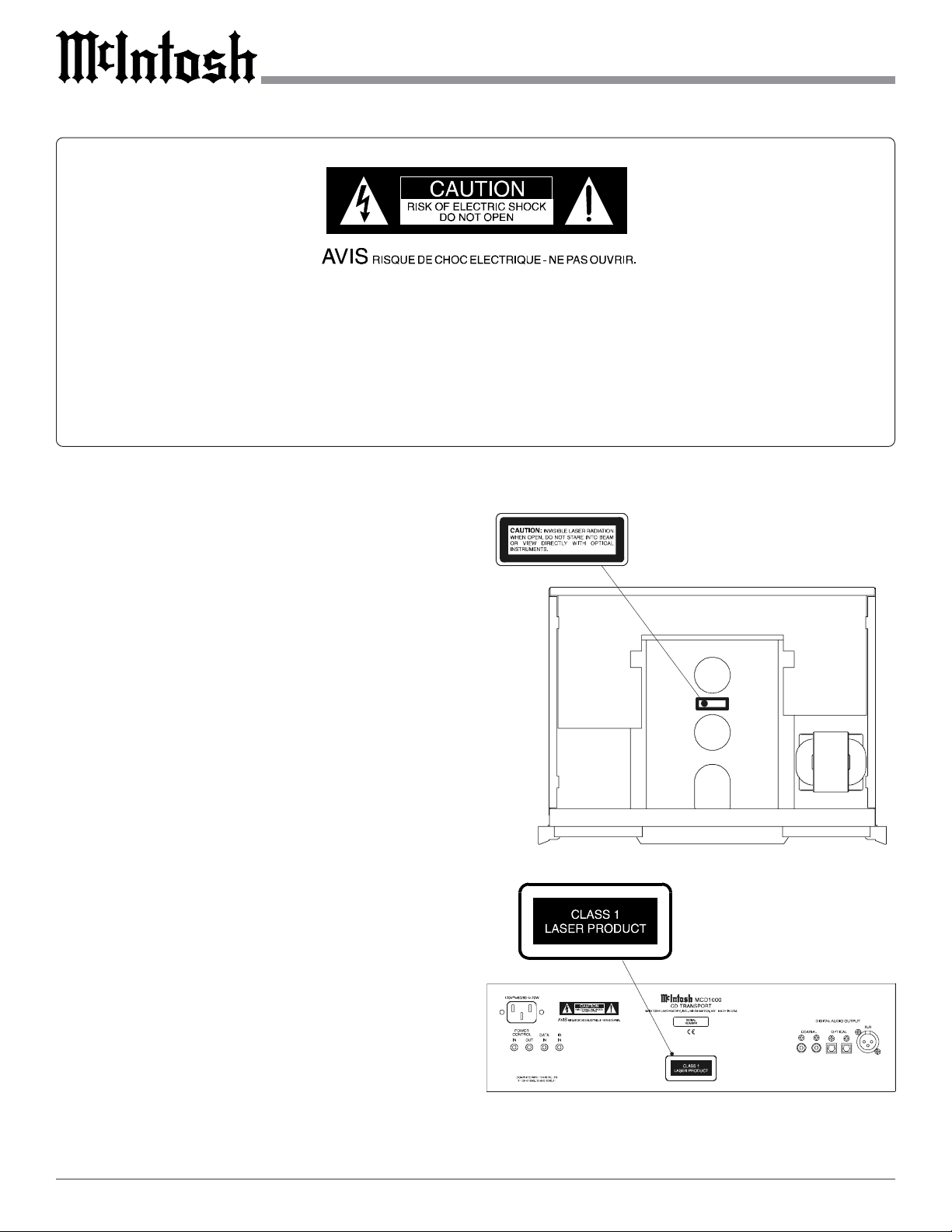
CAUTION -
Invisible Laser Radiation when open. DO
NOT stare into the beam or view directly
with optical instruments. Use of controls or
adjustment or performance of procedures
other than those specified in the Owners
Manual may result in Hazardous Radiation
Exposure.
LUOKAN 1 LASERLAITE
KLASS 1 LASER APPARAT
NO USER-SERVICEABLE PARTS
INSIDE. REFER SERVICING TO
QUALIFIED PERSONNEL.
T o prevent the risk of electric shock, do not remove cover or
back. No user serviceable parts inside.
VAROITUS!
VARNING!
This product incorporates an embedded
2
Laitteen kayttaminen muulla kuin
tassa kayttoohjeessa mainitulla tavalla
saattaa altistaa kaytt ajan
turvallisuusluokan 1 ylittavalle
nakymattomalle lasersateiiylle.
Om apparaten anvands pa annat satt
an i denna bruksanvisning
specificerats, kan anvandaren utsattas
for osynbg laserstraining, som
overskrider gransen for laserklass 1.
CLASS 1 Laser (CFR).
Page 3

IMPORTANT SAFETY
INSTRUCTIONS!
PLEASE READ THEM BEFORE
OPERATING THIS EQUIPMENT.
1. Read these instructions.
2. Keep these instructions.
3. Heed all warnings.
4. Follow all instructions.
5. Do not use this apparatus near water.
6. Clean only with a dry cloth.
7. Do not block any ventilation openings. Install in
accordance with the manufacturer’s instructions.
8. Do not install near any heat sources such as
radiators, heat registers, stoves, or other
apparatus (including amplifiers) that produce heat.
9. Do not defeat the safety purpose of the polarized
or grounding-type plug. A polarized plug has two
blades with one wider than the other . A grounding
type plug has two blades and a third grounding
prong. The wide blade or the third prong are
provided for your safety. If the provided plug
does not fit into your outlet, consult an electrician
for replacement of the obsolete outlet.
10. Protect the power cord from being walked on or
pinched particularly at plugs, convenience
receptacles, and the point where they exit from
the apparatus.
11. Only use attachments/accessories specified by the
manufacturer.
12. Use only with the cart, stand, tripod, bracket, or
table specified by the manufacturer, or
sold with the apparatus. When a cart
is used, use caution when moving the
cart/apparatus combination to avoid
injury from tip-over .
13. Unplug this apparatus during lightning storms or
when unused for long periods of time.
14. Refer all servicing to qualified service personnel.
Servicing is required when the apparatus has been
damaged in any way , such as power -supply cord
or plug is damaged, liquid has been spilled or
objects have fallen into the apparatus, the
apparatus has been exposed to rain or moisture,
does not operate normally, or has been dropped.
15. Do not expose this equipment to dripping or
splashing and ensure that no objects filled with
liquids, such as vases, are placed on the
equipment.
16. To completely disconnect this equipment from the
a.c. mains, disconnect the power supply cord
plug from the a.c. receptacle.
17. The mains plug of the power supply cord shall
remain readily operable.
3
Page 4

Thank Y ou
Table of Contents
Your decision to own this McIntosh MCD1000 CD Transport ranks you at the very top among discriminating music
listeners. You now have “The Best.” The McIntosh dedication to “Quality ,” is assurance that you will receive many
years of musical enjoyment from this unit.
Please take a short time to read the information in this
manual. We want you to be as familiar as possible with all
the features and functions of your new McIntosh.
Please Take A Moment
The serial number, purchase date and McIntosh Dealer
name are important to you for possible insurance claim or
future service. The spaces below have been provided for
you to record that information:
Serial Number:
Purchase Date:
Dealer Name:
T echnical Assistance
If at any time you have questions about your McIntosh
product, contact your McIntosh Dealer who is familiar with
your McIntosh equipment and any other brands that may be
part of your system. If you or your Dealer wish additional
help concerning a suspected problem, you can receive technical assistance for all McIntosh products at:
McIntosh Laboratory , Inc.
2 Chambers Street
Binghamton, New York 13903
Phone: 607-723-1545
Fax: 607-723-3636
Customer Service
If it is determined that your McIntosh product is in need of
repair, you can return it to your Dealer. You can also return
it to the McIntosh Laboratory Service Department. For assistance on factory repair return procedure, contact the
McIntosh Service Department at:
McIntosh Laboratory , Inc.
2 Chambers Street
Binghamton, New York 13903
Phone: 607-723-3515
Fax: 607-723-1917
Copyright 2003 © by McIntosh Laboratory, Inc.
Safety Instructions ............................................................ 2
Thank You and Please T ake a Moment ............................. 4
T echnical Assistance and Customer Service ..................... 4
T able of Contents .............................................................. 4
Important Information....................................................... 4
Connector Information ...................................................... 5
Introduction....................................................................... 5
Performance Features ....................................................... 5
Dimensions........................................................................ 6
Installation ........................................................................ 7
Rear Panel Connections ..................................................... 8
How to Connect ................................................................. 9
Front Panel Indicator, Push-buttons and Switch.............. 10
Front Panel Display ......................................................... 11
Remote Control Push-buttons .......................................... 12
How to Operate the Remote Control ................................ 13
How to Operate the MCD1000........................................ 14
Specifications ................................................................... 22
Packing Instructions......................................................... 23
Important Information
1. It is recommended that a qualified professional assist you in
the choice and installation of a McIntosh Audio System for
your home.
2. Before making any connections to the MCD1000, make sure
that the Main POWER Switch is in the Off position. When
the MCD1000 and other McIntosh Components are in their
Standby Mode the Microprocessor’s Circuitry inside each
component is active and communication is occurring
between them. Failure to do so could result in
malfunctioning of some or all of the system’s normal
operations.
3. The following Connecting Cable is available from the
McIntosh Parts Department:
Data and Power Control Cable Part No. 170-202
Six foot, 2 conductor shielded, with two 1/8 inch stereo
mini phone plugs.
4. When the MCD1000 Digital XLR Output is used to connect
with the Digital XLR Input of the McIntosh MDA1000 D/A
Converter, it is important to use a twisted pair shielded
cable.
5. For additional connection information, refer to the owner’s
manual(s) for any component(s) connected to the
MCD1000.
6. The MCD1000 basic transport functions may also be
controlled by using the Remote Control that comes with a
McIntosh Control Center or Preamplifier. McIntosh
Keypads connected to a McIntosh Control Center or
Preamplifier will also allow remote operation.
7. Before moving or transporting the MCD1000 CD Transpor t
remove any CD Disc from the tray to prevent possible
damage to the Transport and/or Discs.
4
Page 5
8. The MCD1000 Compact Disc Player is designed to play all
standard CD Discs that conform to the Official Compact
Disc Standards which is indicated by the Symbol. It
will also play most CD-R discs, however some discs may
not be able to play due to the condition of the recording.
9. Compact Discs that are not round (e.g. Novelty discs with
octagonal or heart shapes) will not play properly in the
MCD1000 and should not be tried, as possible damage may
occur.
10. The following list of Compact Disc Accessories should not
be used with the MCD1000:
A. Compact Disc Stabilizers.
B. Disc Protectors.
C. Lens/Laser Cleaning Discs and devices.
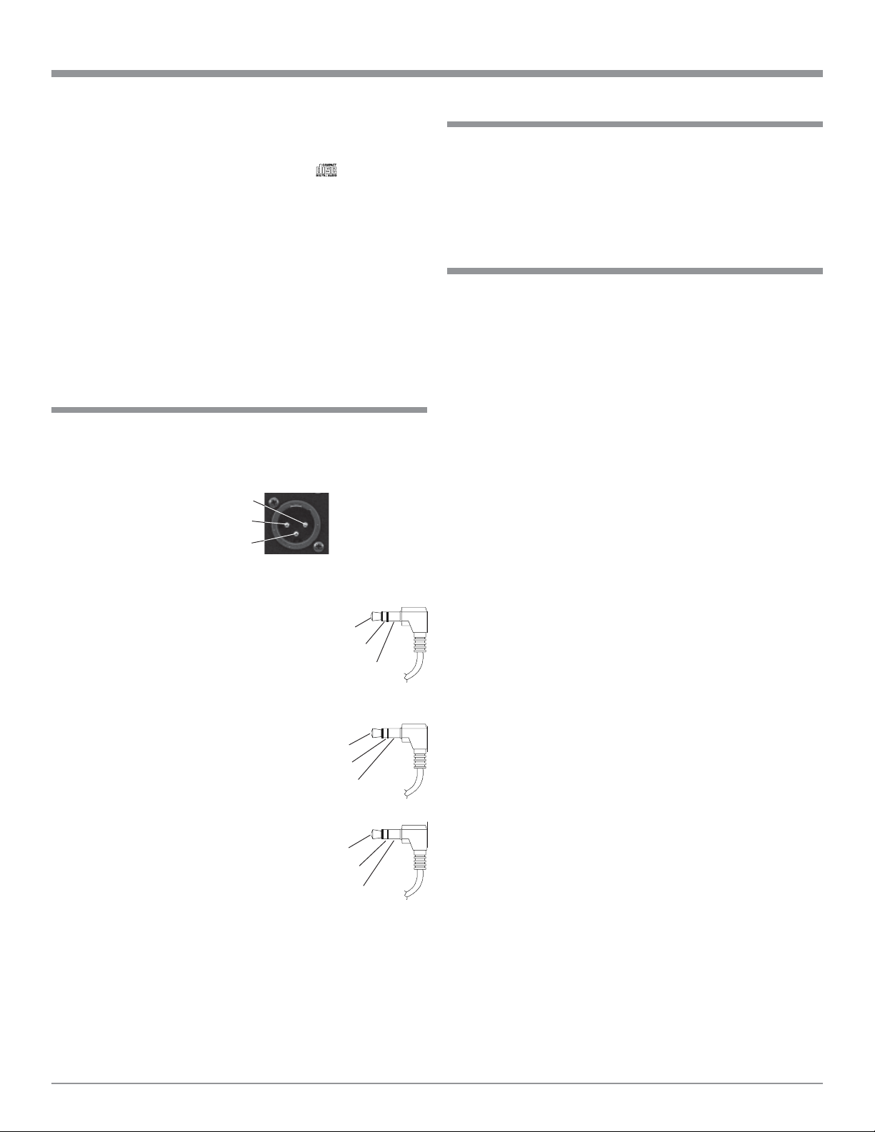
Connector Information
XLR Connectors:
Below is the Pin configuration for the XLR Balanced Digital Audio Output Connectors on the MCD1000. Refer to the
diagram for connection:
PIN 1: Shield/Ground
PIN 2: + Signal
PIN 3: - Signal
Power Control and T rigger Connectors
The MDA1000’ s Power Control Outputs provide a 5 volt
signal. Use a 1/8 inch stereo mini phone
plug to connect to the Power Control Input on other McIntosh Components.
Data and IR Port Connectors
The MDA1000’ s Data Port Output provides Remote Control Signals and the IR
Input Port allows for the
connection of other
brands IR Sensors. Use a
1/8 inch stereo mini
phone plug to connect to
the Data Port Inputs on
McIntosh Source Units.
Pin 2
Pin 1
Pin 3
Positive
N/C
Ground
Data Port Connector
Data Signal
N/C
Data Ground
IR Input Port Connector
Data Signal
N/C
Ground
Introduction and Performance Features
Introduction
The McIntosh MCD1000 CD Transport of fers the latest in
technology and provides state of the art reproduction of
Compact Discs. A full complement of performance features
together with the advanced mechanical design ensures many
years of smooth trouble free operation.
Performance Features
••
• Advanced Transport
••
The MCD1000 has a custom designed precision-machined
metal disc tray for safe and gentle disc handling. The servocontrolled transport with a shock resistant suspension incorporating the latest in error correction circuitry for reading
imperfect discs.
••
• Four Playback Modes
••
The MCD1000 Compact Disc Player allows for Disc Playback, Intro Playback, Program Playback and Random Playback.
••
• Front Panel Display
••
The Display indicates the Disc, T rack and T ime information
along with the Playback Mode in use.
••
• Remote Power , Data Contr ol and External IR Input
••
Remote Power Control In/Out allows the MCD1000 to turn
On/Off with a McIntosh Audio Control Center. The Data
Port Input allows Remote Control Operation from another
McIntosh Component. The IR Input allows for the connection of an IR Receiver.
••
• Special Power Supply
••
A fully regulated Power Supply with a special R-Core
Power Transformer , ensures stable noise free operation even
though the power line varies.
••
• Fiber Optic Solid S tate Front Panel Illumination
••
The Illumination of the Glass Front Panel, with a three dimensional look, is accomplished by the combination of custom designed Fiber Optic Light Diffusers and extra long life
Light Emitting Diodes (LEDs). This provides even Front
Panel Illumination and is designed to ensures the pristine
beauty of the MCD1000 will be retained for many years.
••
• Machined T op and Side Panels
••
The Top and Side of the MCD1000 are machined from
thick aluminum panels with a smooth black anodized finish.
In the recessed area of the Top Panel is a screened glass
panel with a block diagram of the MCD1000’s circuitry.
5
Page 6
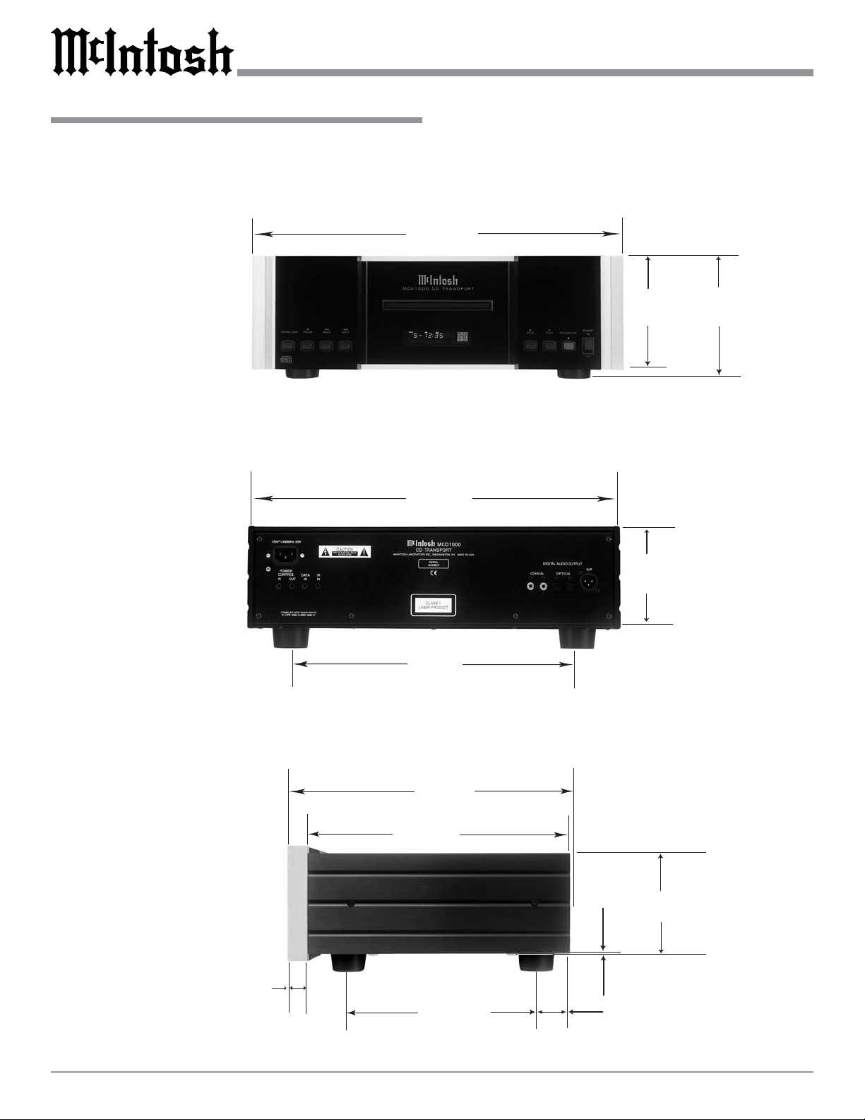
Dimensions
The following dimensions can assist in determining the best
location for your MCD1000. There is additional information on the next page pertaining to installing the MCD1000
into cabinets.
17-
1/2
44.45cm
Dimensions
"
Front View
of the
MCD1000
Rear View
of the
MCD1000
17"
43.18cm
13-
1/4
33.65cm
5-
5/16
"
6"
13.49cm
4-
5/8
11.75cm
15.24cm
"
"
15-
7/8
"
40.32cm
12
-1/8
"
30.79cm
Side View
of the
MCD1000
15/16
"
2.38cm
6
9
"
22.86cm
3/16
"
0.48cm
1-
3.65cm
4-
13/16
12.22cm
7/16
"
"
Page 7
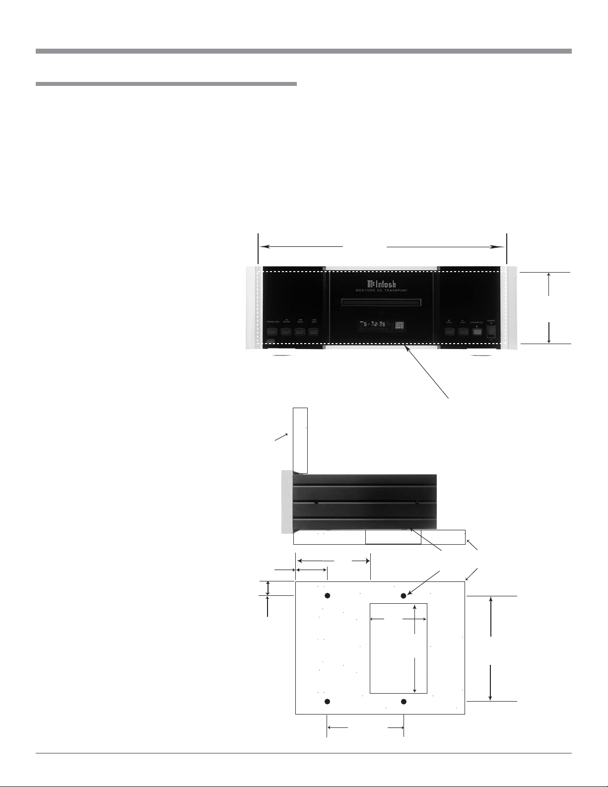
Installation
The MCD1000 can be placed upright on a table or shelf
standing on its four feet. It also can be custom installed in a
piece of furniture or cabinet of your choice. The four feet
may be removed from the bottom of the MCD1000 when it
is custom installed as outlined below. The four feet together
with the mounting screws should be retained for possible
future use if the MCD1000 is removed from the custom installation and used free standing. The required panel cutout,
ventilation cutout and unit dimensions are shown.
Always provide adequate
ventilation for
your
MCD1000.
Cool operation
ensures the
longest possible
operating life
for any electronic instrument. Do not
install the
MCD1000 directly above a
heat generating
component such
as a high powered amplifier .
If all the components are installed in a
single cabinet, a
quiet running
ventilation fan
can be a definite asset in
maintaining all
the system components at the
coolest possible
operating temperature.
A custom
cabinet installation should provide the following minimum
spacing dimen-
MCD1000 Front Panel
Custom Cabinet Cutout
MCD1000 Side View
in Custom Cabinet
MCD1000 Bottom View
in Custom Cabinet
Cabinet
Front
Panel
3-
3/32
7.86cm
1"
2.54cm
"
Installation
sions for cool operation. Allow at least 2 inches (5.08cm)
above the top, 2 inches (5.08cm) below the bottom and 1
inch (2.54cm) on each side of the CD T ransport, so that airflow is not obstructed. Allow 17 inches (43.18cm) depth behind the front panel. When a CD Disc is inserted or removed, the panel clearance required in front of the mounting
panel is 3-3/4 inches (9.5cm). Be sure to cut out a ventilation hole in the mounting shelf according to the dimensions
in the drawing.
17-
1/16
"
43.34cm
4-
7/8
"
12.38cm
Cutout Opening for Custom Mounting
Cutout Opening
for Ventilation
7"
17.78cm
6
15.79cm
4
10.16cm
-7/32
Chassis
Spacers
"
12"
30.48cm
Cutout
Opening
for
Ventilation
"
Support
Shelf
13-
1/4
33.66cm
"
7
Page 8
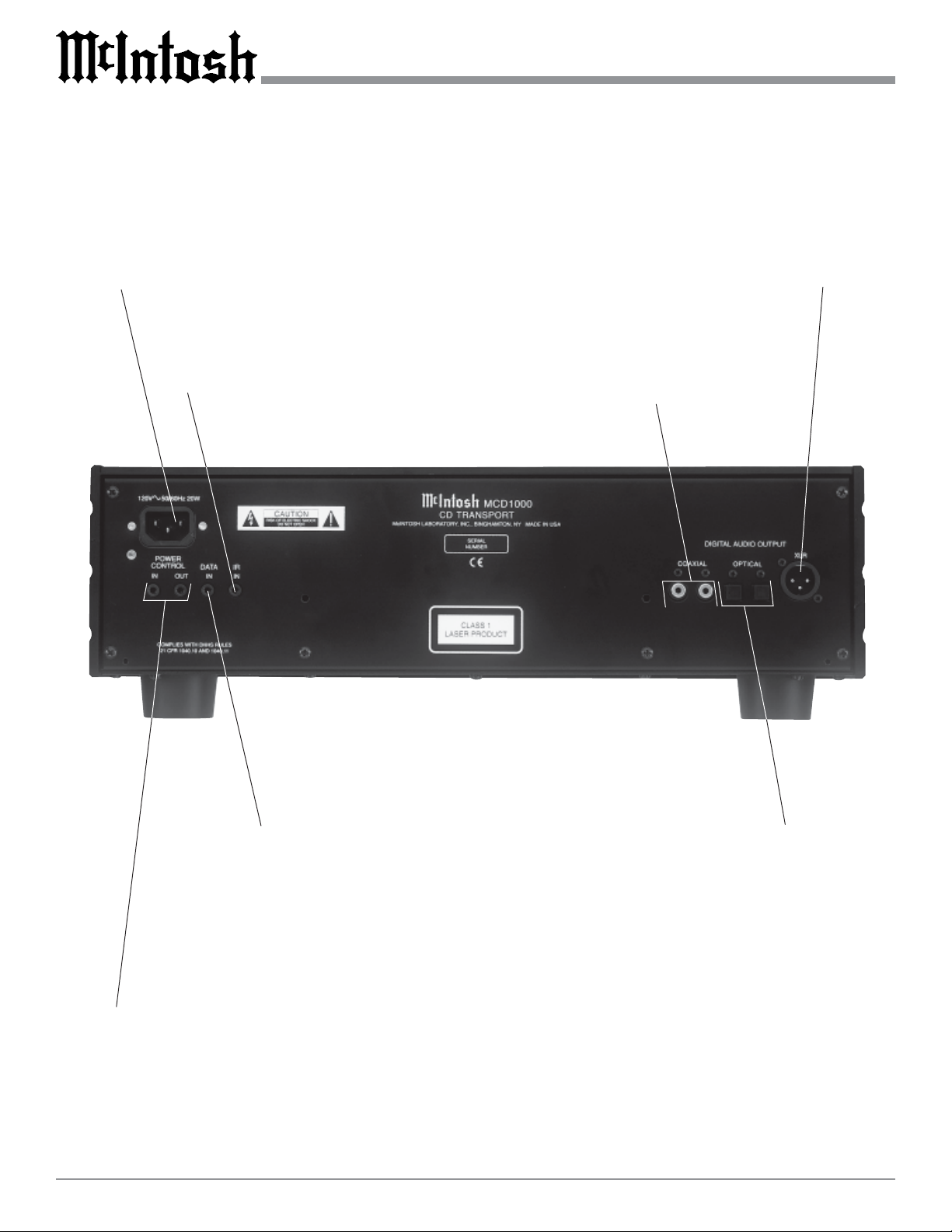
Rear Panel Connections
Connect the MCD1000
power cord to a live
AC outlet. Refer to information on the back
panel to determine the
correct voltage
IR INPUT for
connecting an
IR Receiver
Balanced XLR DIGITAL AUDIO OUTPUT sends digital
audio signals from the McIntosh MCD1000 CD Transport
to the MDA1000 D/A Converter
COAXIAL DIGITAL
AUDIO OUTPUTS
send digital audio
signals to a D/A Converter
DATA IN receives
operating data from
a McIntosh Control
Center
POWER CONTROL IN
receives turn-On signals
from a McIntosh Component and POWER CONTROL OUT sends turn-On
signals on to another McIntosh Component
8
OPTICAL DIGITAL
AUDIO OUTPUTS
sends digital audio
signals to a D/A Converter
Page 9

How to Connect
1. Connect a Power Control Cable from the MDA1000
Power Control Out Jack to the POWER CONTROL IN
Jack on the McIntosh MCD1000.
Notes: 1. If the MCD1000 CD Transport is not
connected to a McIntosh MDA1000 D/A
Converter and instead connected to a
McIntosh A/V Control Center with digital
inputs, the MCD1000’s Power Control In
should be connected to the appropriate Power
Control Out Jack on the A/V Control Center.
2. When the MCD1000 and MDA1000 are
connected in a non-McIntosh Preamplifier
System, the Power Control Cable should be
connected from the MCD1000 Power Control
Out to the MDA1000 Power Control In.
2. Connect a Data Control Cable from the MDA1000
Line 1 Switched Data Output Jack to DAT A IN Port on
the McIntosh MCD1000.
How to Connect
Note: If the MCD1000 CD Transport is not connected to
a McIntosh MDA1000 D/A Converter and instead
connected to a McIntosh A/V Control Center with
digital inputs, the MCD1000’s Data In should be
connected to the appropriate Data Out Jack on the
A/V Control Center.
3. Connect a Coaxial Digital Cable from the MDA1000
Coaxial 1 Digital Audio Input to either COAXIAL
DIGITAL AUDIO OUTPUT Jack on the MCD1000.
Note: When the MCD1000 CD Transport is connected to
a McIntosh MDA1000 D/A Converter the Digital
Optical Output or the Balanced Digital XRL
Output may be used instead of the Coaxial Digital
Output. If MCD1000 CD Transport is connected to
a McIntosh A/V Control Center with digital inputs
either the Coaxial or Optical Outputs my be used.
4. Connect the MCD1000 Power Cord to a live AC outlet.
T o AC Outlet
McIntosh MDA1000 D/A Converter
9
Page 10

Front Panel Indicator , Push-Buttons and Switch
Open and Close
the Disc Door for
loading or unloading discs
Disc Tray opens to
permit the loading
and unloading of a
disc
IR Sensor receives
commands from a
remote control
Front Panel
Display
Power Switch turns all
AC power completely
On or Off
Standby Power
On Light
Use to pause
during Playback
10
Move back
one track at
a time
Move forward
one track at a
time
Stops disc
Playback
Standby/On Pushbutton turns the
MCD1000 On or
Off (Standby)
Starts disc
Playback
Page 11

Front Panel Display
Indicates the Program Track Play
Mode is active
Indicates Track
Number
Indicates the current Track
Time, Remaining Track
Time, Total Disc Playing
Time and various Programming information
Indicates the
Number of Tracks
and the Total
Playing Time of
the Disc when the
player is stopped
Indicates when
the Time Display
is showing the
Remaining Time
Indicates the number
of tracks on the disc
and the Program
Step Number(s)
Indicates the Random
Track Play Mode is
active
Indicates when in
the Play Mode
Indicates when
in the Pause
Mode
Indicates when the
Repeat All Play
Mode is active
Indicates when the
first ten seconds of
each track is being
played
Indicates when the
A-B Repeat Play
Mode is active
11
Page 12

Press a Number Push-button
to select the desired Track
Remote Control Push-Buttons
Press the Up or Down
Push-button to adjust the
volume level of the
MDA1000
Use to Program
specific tracks for
playback
Press to move
rapidly backward
through a Track
on the Disc
Press to move
rapidly forward
through a Track
on the Disc
Press to sample
the first 10 seconds of each
Track on the
Disc
Press the Input push-button
followed by pressing one of
the Numbered Push-Buttons
to select the desired Digital
Input of the MDA1000
Press to display the Current
Track Time, Elasped Time
or Total Disc Time
Move forward one Track at a
time
Move backward one Track at a
time
Press to activate Random
Track Playback
12
Press to Repeat
various Playback
Modes
Press to Stop
Disc Playback
at any time
Starts Standard Disc Playback and Program Playback
Press to Pause
Disc Playback at
any time
Notes: The Remote Control illustrated above is supplied with the matching
MDA1000 D/A Converter. It is also available as an accessory for the
MCD1000, check with your McIntosh Dealer for additional details. The
buttons with the “small text descriptions” are used to control various
functions of the McIntosh MDA1000 D/A Converter.
Page 13

How to Operate the Remote Control
How to Operate the Remote Control
Numbered Push-buttons
Press a NUMBER Push-button (1 through 9) followed by
pressing the PLA Y Push-button to directly access the desired disc track. Track numbers above 9 require the pressing
of two NUMBER Push-buttons. If the desired Track Number is higher than 9, first press and hold down the NUMBER Push-button until the number entered shifts its position
to the “T ens Digit”, as indicated on the Front Panel
Aphanumeric Display , followed by pressing the NUMBER
Push-button for the “Units Digit”.
Program
The PGM(Program) Push-button is used to enter desired
Track Selections into memory for Playback. Refer to page
17 for additional information on Programming.
Intro
Press the INTRO Push-button to audition the first 10 seconds of each track on the CD Disc.
Random
Press the RANDOM Push-button to playback Tracks in a
random order.
Repeat
Press the REPEAT Push-button to allow continuous playback of Standard Play Mode, Random Play Mode or Program Play Mode.
MCD1000
Function
Back and Next
Press the NEXT Push-button to move forward or the
BACK Push-button to move backward one track at a
time.
REV and FF
Press the REVerse Push-button or FF(Fast Forward)
Push-button to start moving rapidly through a track.
Note: Audio level is automatically reduced during this
operating mode.
Stop
Press the STOP Push-button to stop the disc playing.
Alternate Remote Control Push-button Functions
Most basic MCD1000 Operating Functions can be performed with Remote Controls of McIntosh A/V Controllers,
A/V Control Centers or Preamplifiers and McIntosh Keypads. Additional MCD1000 functions can be performed
with other McIntosh Remote Controls by using push-buttons that are labeled differently from the Compact Disc Remote Control. The chart below lists the MCD1000 operations that can be performed by these different pushbuttons
on Remote Controls of other McIntosh products.
Other McIn tosh Remote Control Devices
A/ V Con t r ol
Center
WK2
Keypad
WK3
Keypad
WK4
Keypad
Play
Press the PLAY Push-button to start Playback
of the currently selected disc or a stored Program.
Time
During standard Disc Playback, pressing the
TIME Push-button will allow the Front Panel
Alphanumeric Display to indicate either the Current Track Time, T rack Elapsed Time, Track Remaining T ime, Disc Elapsed T ime, Disk Remaining T ime or only the T rack Number.
Note: These five Track/Time Display Modes are
not available during Intro Play Mode,
Random Play Mode and Program
Playback.
Play Play Play Play Play
Stop Stop Stop Stop Stop
Pause Pause - -
Next Next Next Next Next
Back Back Back - Back
Fast Forward Fast Forward Seek Up - Channel Up
Fa st R everse Fast Reve rse Se ek Down - Channel Down
Numbe r s 0- 9 Numbe r s 0- 9 N umbe r s 0- 9 - N umbe r s 0- 9
Pause
Press the PAUSE Push-button to momentarily stop Playback operation at any time. Press the PLAY Push-button
to resume Playback of the disc.
13
Page 14

How to Operate the MCD1000
Press the POWER switch to ON, the Red LED above the
ST ANDBY/ON Push-button lights to indicate the
MCD1000 is in Standby Mode. To Switch On the
MCD1000 press the STANDBY/ON Push-button. With no
CD Disc loaded in the CD T ransport the Front Panel Alphanumeric Display will indicate “Track 0” Refer to figures 1
and 8.
Notes: For normal operation, switch the MCD1000 On and
Off with the Standby/On Push-button. If the Disc
Player is not going to be used for an extended period
of time, turn Off all AC Power with the Power
Switch. When the MCD1000 Power Control Jack is
connected (via a cable) to a McIntosh MDA1000 D/A
Converter, Control Center, A/V Multizone System
Controller or Preamplifier, the MCD1000 will
automatically switch ON and OFF with the system.
When power is first applied, the MCD1000 will
determine if a disc is present inside and during that
time the OPEN/CLOSE Push-button is not active
until a triangle appears on the Alphanumeric
Display.
ing Tray will draw the Disc into the Transport. Refer to
figure 3.
Disc seated
Figure 3
Note: The Disc Tray will also close by giving the front
edge of the tray a nudge, refer to figure 4.
Give the
Figure 1
Loading a Compact Disc
Before inserting a disc into the MCD1000 CD T ransport
please read Important Notes Numbers 8, 9 and 10 found on
page 5 for important information.
1. Press the Front Panel OPEN/CLOSE Push-button and
the Disc Loading T ray will slide open to permit the insertion of a Disc into the MCD1000. Refer to figures 2
and 8.
Figure 2
2. Insert the disc into the Disc T ray and press the Front
Panel OPEN/CLOSE Push-button and the Disc Load-
Figure 4
3. The Front Panel Alphanumeric Display will indicate the
number of Tracks and the Total playing time. Refer to
figure 5.
Figure 5
4. Press the PLAY Push-button to start playback of the
disc.
Unloading Compact Discs
The steps for removing the disc from the MCD1000 CD
14
Page 15

Transport is similar to the Loading Disc Process, except in
reverse.
1. Press the Front Panel STOP Push-button if a Disc is
playing.
2. Press the OPEN/CLOSE Push-button and the Disc
Loading Tray will slide open to permit removal of the
Disc from the MCD1000 CD Transport.
Disc Playback
Press the PLAY Push-button and the disc will start playing. The Front Panel Display will indicate the current T rack
Number, the Time into the Track and a T riangle. When all
of the tracks on the disc have played the MCD1000 will
stop, unless the Repeat Playback Mode has been activated.
Refer to figure 6.
Figure 6
Direct T rack Selection
T o select a specific track on a Compact Disc perform the
following using a McIntosh Remote Control.
1. Press the NUMBER Push-button to select the desired
Track.
Note: If the desired Track Number is higher than 9, first
press and hold down the NUMBER Push-button until
the number entered shifts its position to the “Tens
Digit” followed by pressing the NUMBER Pushbutton for the “Units Digit”. Refer to figure 7.
Disc Pause
While a Disc is playing, press the PAUSE Push-button to
temporarily stop playback. To cancel the Pause Mode, press
the PLAY Push-button or press the P AUSE Push-button
again and the disc will resume playing. The Front Panel
How to Operate the MCD1000
Figure 7
Display will indicate that the MCD1000 is in Pause Mode
with double vertical rectangles positioned to the right of the
Play Triangle. Refer to figure 9.
Figure 9
Stop Mode
Press the STOP Push-button at any time to stop Disc
Playback. If the MCD1000 is in Random, Intro and/or Program Modes of Playback, pressing the STOP Push-button
will stop playing the disc and cancel the Random, Intro and/
or Program Modes of Playback. Refer to figure 8.
Back Track
Pressing the BACK Push-button while a Disc is playing will either return playback to the beginning of the same
Track or to the previous Track. If the push-button is pushed
once, playback of the current track will start playing. When
the push-button is pushed twice, the previous track will start
playing. Holding down the push-button will allow for rapid
selection of the desired Track.
Next T rack
For each press of the NEXT Push-button the
MCD1000 will advance to the next Track. Holding down
the push-button will allow for rapid selection of the desired
Track.
Figure 8
15
Page 16

Important Operational Information
The optional MDA1000 Remote Control is needed to perform the following Operation Functions:
Fast Forward or Reverse
Press the FF (Fast Forward) or REV (Reverse)
Push-buttons to move back and forth rapidly through the
Track currently playing on a disc. The accelerated sound
will be audible during this operation, at a reduced volume
level. Releasing the push-button will return playback to normal speed and volume level.
T rack and Time Display
The Front Panel Display can indicate five different Disc/
Track T ime Displays; Track Elapsed T ime, T rack Remain-
ing Time, Disc Elapsed Time, Disk Remaining Time and
only the Track Number. With each press of the TIME Pushbutton on the Remote Control, the Front Panel Alphanumeric Display will indicate one of the five different displays. Refer to figures 10 thru 14.
Intro Play Mode
The Introduction Playback Mode when activated, allows for
listening to the first 10 seconds of each track on the CD. To
start the Intro Playback Mode, press the INTRO Push-button on the Remote Control. When the desired track is located, press the PLA Y Push-button on the Remote Con-
trol. This will restart the desired track from the beginning
and cancel the Intro Playback Mode. Refer to figure 15.
Note: The Intro Playback Mode may be cancelled at any time
by pressing the STOP Push-button.
Figure 10
Figure 11
Figure 12
Figure 13
Figure 14
Figure 15
Repeat Mode
This allows continuous playback of all the Tracks on the
disc or a portion of a single track when the MCD1000 is in
the Standard Play Mode. If either the Random and/or Program Modes of Playback are active, the Repeat Mode may
also be activated for continuous playback of those Modes.
1. Press the REPEAT Push-button once to activate the Repeat Mode. The Front Panel Display will indicate the
Repeat Mode is active. Refer to figure 16.
Figure 16
2. Press the REPEAT Push-button twice or the STOP
Push-button to cancel the Repeat Mode.
A-B (Partial Track) Repeat Mode
1. Press the REPEAT Push-button once to activate the Repeat Mode and establish the “A - starting point”, press
the REPEAT Push-button again to set the “B - ending
point”. Refer to figure 17.
Note: The A-B Repeat Mode is intended for use within a
single track.
16
Page 17

Figure 17
2. Press the REPEAT Push-button twice or the STOP
Push-button to cancel the Repeat Mode.
Random Play Mode
The MCD1000 CD Transport has the ability to playback
Tracks in a random order during S tandard Play Mode.
1. Press the RANDOM Push-button to activate the Random Play Mode.
Note: The Front Panel Alphanumeric Display of Pause
“ ” and “Track 1” indicators will momentarily
illuminate while a Random Play List is being
generated in memory. Refer to figure 18.
How to Operate the MCD1000 con’t
and time of each track for the CD disc. The reading of this
information occurs when the Disc Loading T ray draws the
Disc into the CD Transport.
1. Pressing the PGM (Program) Push-button on the Remote Control will activate the Programing Mode of the
MCD1000 CD Transport. Refer to figure 20.
Figure 20
Note: The Front Panel Alphanumeric Display will
indicate the Pause Mode is active, three dashes
appear under Track Number, the Time of the first
Track on the Disc and the First Program Step
Number “ 1 ” will be flashing.
2. Press the PAUSE Push-button and the first track will
start playing and the current memory location is available. Refer to figure 21
Figure 18
2. The Random Play Mode may be repeated by pressing
the REPEAT Push-button after Random playback of
Figure 19
tracks has started. Refer to figure 19.
Note: While in the Random Play Mode, the next random
track may be selected by pressing the NEXT
Push-button or the previous random track by
pressing the BACK Push-button.
3. To cancel the Random Play Mode press the STOP Pushbutton.
Program Playback
The MCD1000 has the ability to store up to 16 different
Program Steps. This allows the playback of desired tracks
in a specific order from the CD Disc. In order to program
tracks from a disc, it is first necessary to read the the Table
of Contents (TOC). The T OC contains the number of tracks
Figure 21
3. To enter this track into memory, press the PGM Pushbutton. If a different track is desired, use either the
NEXT and BACK Push-buttons or the NUM-
BER (0 thru 9) Push-buttons to select the desired track
and then press the PGM Push-button to enter it into
memory . Refer to figure 22.
Figure 22
Note: The Front Panel Alphanumeric Display will
momentarily indicate three dashes under the Track
Number followed by the track number, the First
Program Step Number “ 1 ” is now on
continuously and a flashing Second Program Step
Number “ 2 ” will appear.
4. Additional T rack Selections may be entered into
memory at this time by pressing the PGM Push-button
and selecting the track using the NEXT and
BACK Push-buttons or the NUMBER (0 thru 9).
17
Page 18

How to Operate the MCD1000 con’t
The Front Panel Alphanumeric Display indicates that
Program Steps “ 1 ” and “ 2 ” are on continuously and
the next available Program Step will be flashing. Refer
to figure 23.
Figure 23
5. To start playback of the just entered into memory Program Selections, press the PLA YPushbutton. Refer to
figure 24.
Figure 24
Note: If the first program track selection doesn’t need to
be changed, just press the PGM Push-button and
the second Program Step Location will become
available for changing. Continue to press the
PGM Push-button until the track to be changed is
audible and perform step 3 to enter the new
selection.
4. Add any new program steps by repeating step 3.
5. To start playback of the Program Selections just entered
into memory , press the PLA YPushbutton.
Resetting of Micropr ocessors
In the event that the controls of the MCD1000 stop functioning, place the POWER Switch in the OFF position for 5
seconds, then back ON. This will reset the MCD1000 Microprocessors.
Deleting a Program
The MCD1000 will keep an entered Program in its nonvolatile memory for Playback, even if AC Power is removed. To
delete the Program stored in memory press the Front Panel
OPEN/CLOSE Push-button.
Modify a Program
Sometimes after a Playback Program has been created, it
might be desirable to make changes to the existing Program
instead of deleting it and starting all over again.
Note: Changes to a program include the changing of any
tracks currently entered into memory and adding new
program steps to the end.
1. Press the PGM (Program) Push-button on the Remote
Control to activate the Programing Mode on the
MCD1000.
2. Press the PAUSE Push-button and the first track of
the stored program will start playing.
3. To change the first progam track use either the
NEXT and BACK Push-buttons or the NUM-
BER (0 thru 9) Push-buttons to select the new track and
then press the PGM Push-button to enter it into the current memory location.
18
Page 19

Notes
19
Page 20

20
Page 21

Notes
21
Page 22

Specifications
Digital Audio Format
IEC958, S/PDIF
Digital Outputs
Optical: -15 ~ -20dBm
Coaxial: 0.5Vp-p @75ohms
XRL: 5V p-p @110 ohms (AES/EBU)
Transport
Pickup: Optical 3-beam laser
Objective Lens Drive System: 2-Dimensional parallel
Laser T ype: GaAIAs semiconductor
Laser Beam W avelength: 780nm
Digital Signal Format
Sampling Frequency: 44.1kHz
Quantization Bit: 16-bit linear/channel
Modulation Code: Eight to Fourteen Modulation
Error Correction: Cross Interleave Reed Solomon
Specifications
Power Requirements
100 Volts 50/60Hz, 20 watts
110 Volts 50/60Hz, 20 watts
120 Volts 50/60Hz, 20 watts
220 Volts 50/60Hz, 20 watts
230 Volts 50/60Hz, 20 watts
240 Volts 50/60Hz, 20 watts
Note: Refer to the rear panel of the MCD1000 for the correct
voltage.
Overall Dimensions
Width is 17-1/2 inches (44.45cm)
Height is 6 inches (15.24cm) including feet
Depth is 16-1/8 inches (40.96cm) including the Front Panel
and Knobs
Weight
27.5 pounds (12.47 kg) net, 41.5 pounds (18.83 kg) in shipping carton
22
Page 23

Packing Instructions
Packing Instructions
In the event it is necessary to repack the equipment for shipment, the equipment must be packed exactly as shown below.
It is very important that the four plastic feet are attached to the bottom of the equipment. This will ensure the
proper equipment location on the bottom pad. Failure to do
this will result in shipping damage.
Use the original shipping carton and interior parts only if
they are all in good serviceable condition. If a shipping carton or any of the interior part(s) are needed, please call or
write Customer Service Department of McIntosh Laboratory . Please see the Part List for the correct part numbers.
Quantity Part Number Description
1 034075 Shipping carton only
4 033837 End cap
1 034076 Inside carton only
1 033726 Top pad
1 034255 Bottom pad
1 034077 Inner carton pad
4 017937 Plastic foot
4 100159 #10-32 x 3/4” screw
4 104083 #10-7/16” Flat washer
23
Page 24

McIntosh Laboratory, Inc.
2 Chambers Street
Binghamton, NY 13903
The continuous improvement of its products is the
policy of McIntosh Laboratory Incorporated who
reserve the right to improve design without notice.
Printed in the U.S.A.
McIntosh Part No. 040889
 Loading...