

McIntosh MCC-404 Owners Manual
MCC404/MCC404M Power Amplifier
Owners
Manual
MCC404
MCC404M
McIntosh Laboratory, Inc. 2 Chambers Street Binghamton, New York 13903-2699 Phone: 607-723-3512 FAX: 607-724-0549

WARNING - TO REDUCE RISK OF
FIRE OR ELECTRICAL SHOCK, DO
NOT EXPOSE THIS EQUIPMENT TO
RAIN OR MOISTURE.
IMPORTANT SAFETY INSTRUCTIONS!
PLEASE READ THEM BEFORE OPERATING THIS EQUIPMENT.
NO USER-SERVICEABLE PARTS
INSIDE. REFER SERVICING TO
QUALIFIED PERSONNEL.
To prevent the risk of electric shock, do not remove
bottom cover. No user serviceable parts inside.
General:
1. Read these instructions.
2. Keep these instructions.
3. Heed all warnings.
4. Follow all instructions.
5. Warning: To reduce risk of fire or electrical shock,
do not expose this equipment to rain or moisture.
This unit is capable of producing high sound pressure levels. Continued exposure to high sound pressure levels can cause permanent hearing impairment or loss. User caution is advised and ear protection is recommended when playing at high volumes.
6. Disconnect this equipment when unused for long periods of time.
7. Only use attachments/accessories specified by the
manufacturer.
Installation:
8. Do not block any ventilation openings. Install in accordance with the manufacturers instructions.
9. Do not install near any heat sources such as radiators,
heat ducts or other equipment that produce heat.
10. Do not use this equipment near water.
11. Do not expose this equipment to dripping or splashing
and ensure that no objects filled with liquids are
placed on the equipment.
12. Do not mount this product with an unstable bracket as
the equipment may fall, causing serious injury to a
person, and serious damage to the product.
Connection:
13. Route DC power cords so that they are not likely to be
pinched by items placed upon or against them, paying
particular attention to the point where they enter the
instrument.
Care of Equipment:
14. Clean only with dry cloth.
15. Do not permit objects or liquids of any kind to be
pushed, spilled and/or fall into the equipment through
enclosure openings.
Repair of Equipment:
16. Refer all servicing to qualified service personnel. Servicing is required when the equipment has been damaged in any way, such as power-supply cord or plug is
damaged, liquid has been spilled or objects have fallen
into the equipment, the equipment has been exposed to
rain or moisture, does not operate normally, or has
been dropped.
17. Do not attempt to service beyond that described in the
operating instructions. All other service should be referred to qualified service personnel.
18. When replacement parts are required, be sure the service technician has used replacement parts specified by
McIntosh or have the same characteristics as the original part. Unauthorized substitutions may result in fire,
electric shock, or other hazards.
19. Upon completion of any service or repairs to this product, ask the service technician to perform safety checks
to determine that the product is in proper operating
condition.
2
McIntosh MCC404 Amplifier
Thank You
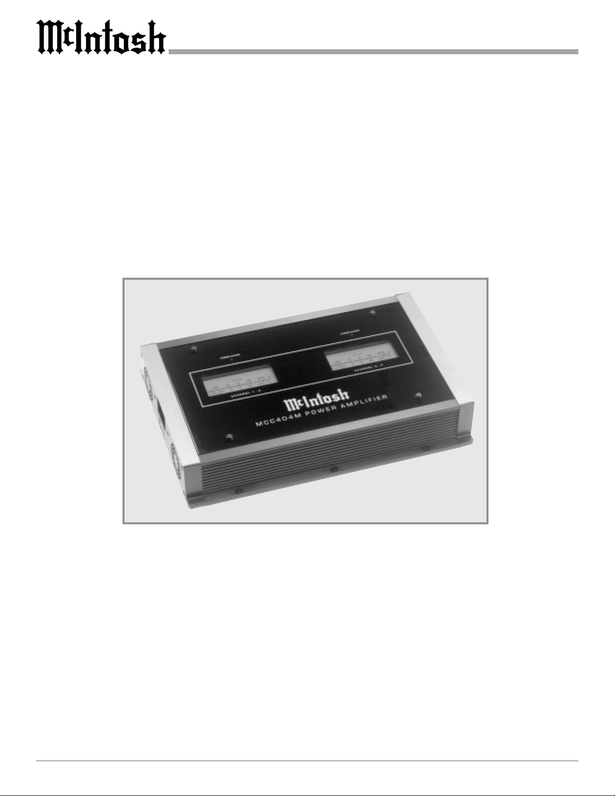
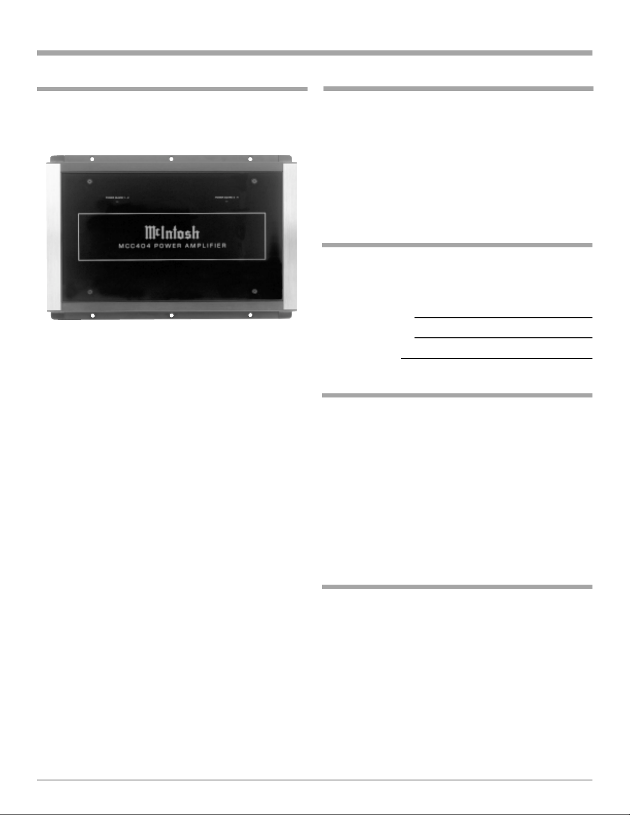
The McIntosh MCC404 Power Amplifier is identical to the
McIntosh MCC404M illustrated throughout this manual in
every aspect except the MCC404 is without the Power Output Meters.
Your decision to own this McIntosh MCC404/MCC404M
Four Channel Power Amplifier ranks you at the very top
among discriminating music listeners. You now have The
Best. The McIntosh dedication to Quality, is assurance
that you will receive many years of musical enjoyment
from this unit.
Please take a short time to read the information in this
manual. We want you to be as familiar as possible with all
the features and functions of your new McIntosh.
Please Take A Moment
The serial number, purchase date and McIntosh dealer
name are important to you for possible insurance claim or
future service. The spaces below have been provided for
you to record that information:
Serial Number:
Purchase Date:
Dealer Name:
Technical Assistance
If at any time you have questions about your McIntosh
product, contact your McIntosh dealer who is familiar with
your McIntosh equipment and any other brands that may
be part of your system. If you or your dealer wish additional help concerning a suspected problem, you can receive technical assistance for all McIntosh products at:
McIntosh Laboratory, Inc.
2 Chambers Street
Binghamton, New York 13903
Phone: 607-723-1545
Fax: 607-723-3636
Customer Service
If it is determined that your McIntosh product is in need of
repair, you can return it to your dealer. You can also return
it to the McIntosh Laboratory Service Repair department.
For assistance on factory repair return procedure, contact
the McIntosh Repair Department at:
McIntosh Laboratory, Inc.
2 Chambers Street
Binghamton, New York 13903
Phone: 607-723-3515
Fax: 607-723-1917
Copyright 2000 ã by McIntosh Laboratory, Inc.
3

Table of Contents
Introduction
Safety Instructions ............................................................. 2
Thank You.......................................................................... 3
Please Take a Moment ....................................................... 3
Customer Service ............................................................... 3
Table of Contents ............................................................... 4
Introduction ....................................................................... 4
Performance Features ........................................................ 4
Dimensions ....................................................................... 5
Installation ........................................................................ 6
Side Panel Cooling and Connections ................................ 7
How to Connect for Four Channels ................................... 8
How to Connect for Three Channels ................................. 9
How to Connect for Two Channels ................................. 10
How to Connect with Subwoofer Channels .................... 11
Top Panel Controls, Displays and Switches .................... 12
How to Operate the MC404/MC404M ............................ 13
How to Operate in Four or Three Channel Mode ............ 14
How to Operate in Two Channel or Subwoofer Mode .... 15
How to Replace the Fuses ............................................... 16
Block Diagram ................................................................. 17
Specifications .................................................................. 18
Packing Instruction .......................................................... 19
General Notes
1. An optional McIntosh External Subwoofer Rotary Control,
Model Number R1163, is available from your McIntosh
Dealer.
2. Do not connect the Amplifier Speaker Negative Terminal
Connection directly to the Vehicle Chassis. Failure to observe
this could result in damage to your Amplifier.
3. For additional connection information, refer to the owner s
manual(s) for any component(s) connected to the MCC404/
MCC404M Amplifier.
4. There is a built-in turn on delay which will mute the speaker
outputs for approximately two seconds when the amplifier is
turned on.
5. It is very important that loudspeaker cables of adequate size
be used in your music system, to ensure that there will be no
power loss or heating. If your loudspeaker cables are 25 feet
(7.62m) or less, use at least 16 Gauge wire size or larger.
6. It is advisable to place an in-line fuse as close as possible to
the battery.
7. The MCC404/MCC404M Line Level OUTPUTs are wired as a
Y connection with the INPUTs to pass the input signals on
to additional amplifiers (keep cable lengths as short as
possible). The McIntosh MX406 Control Center is capable of
driving several additional
power amplifiers with no
degradation of the signal.
8. The MCC404M/MCC404 can
accept speaker level inputs at
its Input Jacks. Refer to the
diagram for connection.
(-) NEGATIVE SPEAKER OUTPUT
(+) POSITIVE SPEAKER OUTPUT
Now you can take advantage of traditional McIntosh standards of excellence in the MCC404/MCC404M power amplifier. Four 100 watt high current output channels will
drive any high quality loudspeaker system to its ultimate
performance. The MCC404/MCC404M reproduction is
sonically transparent and absolutely accurate. The McIntosh Sound is The Sound of the Music Itself.
Performance Features
· Power Output
The MCC404/MCC404M consists of four separate power
amplifier channels, each capable of 100 watts into 4ohm
speakers with less than 0.005% distortion.
· Four Bridgeable Channels
The MCC404/MCC404M includes four 100 watt amplifier
channels. Each pair of channels can be set in bridged configuration for 400 watts output into 4 ohm loudspeakers
with less than 0.007% distortion.
· High Current Output
A peak output current of 20 amperes ensures that the
MCC404/MCC404M will successfully drive high quality
loudspeakers, such as McIntosh, for a truly exciting sound
experience.
· Equalizer and Variable Crossover Filters
The one band equalizer has a center frequency that is variable from 40 Hz to 2,000 Hz that can be either cut or
boosted ±12db. 12dB per octave high pass filters with variable corner frequencies from 5Hz to 5,000Hz and 12dB per
octave low pass filters with variable corner frequencies
from 50Hz to 5,000Hz.
· Power Guard and Sentry Monitor
All channels include the patented McIntosh Power Guard
circuit that prevents the amplifier from being overdriven
into clipping with its harsh distorted sound that can also
damage your valuable loudspeakers. McIntosh Sentry
Monitor power output stage protection circuits are present
on all channels to ensure the MCC404/MCC404M will
have a long and trouble free operating life.
· Speaker Protection
If for any reason, a DC (Direct Current) voltage appears at
the speaker output terminals, a built-in circuit turns off the
amplifier power supplies to prevent damage to your valuable loudspeakers.
4
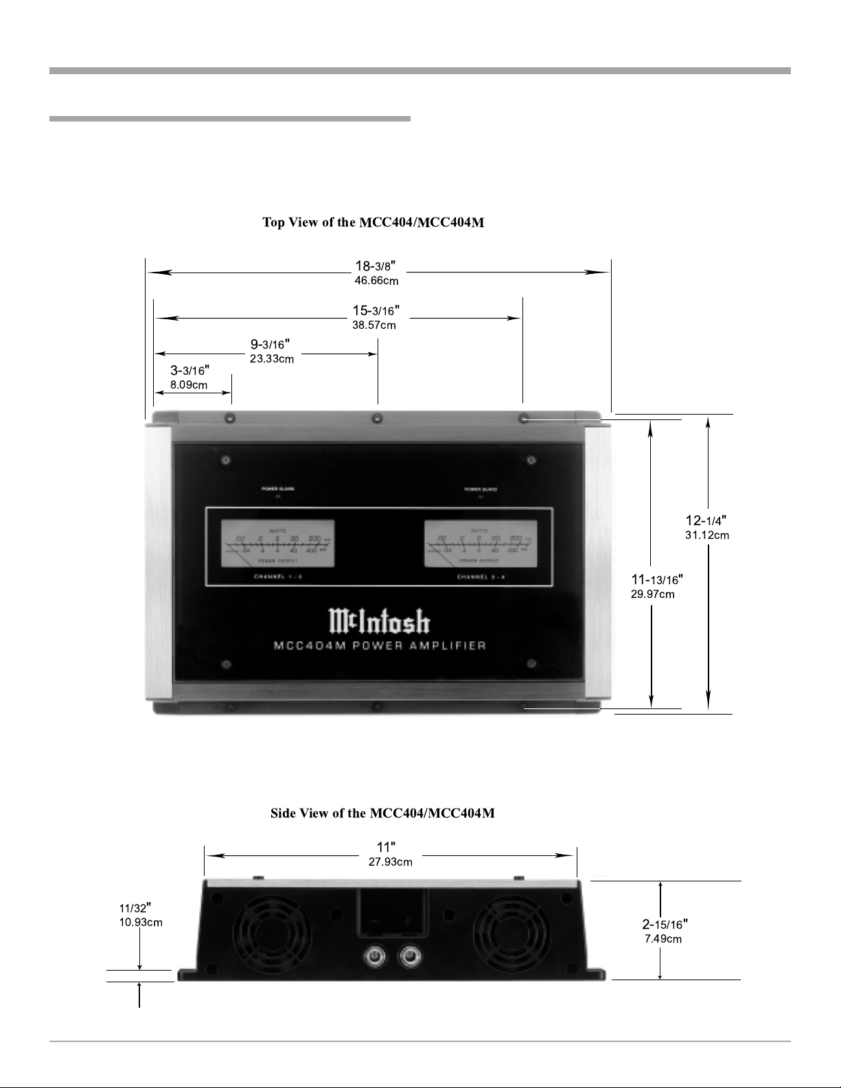
Dimensions
The following dimensions can assist in determining the
best location for your MCC404/MCC404M. There is additional information on the next page pertaining to installing
the MCC404/MCC404M into your vehicle.
Top View of the MCC404/MCC404M
18-
3/8
"
46.66cm
15-
3/16
38.57cm
9-
3/16
"
3-
3/16
8.09cm
"
23.33cm
Dimensions
"
11/32
"
10.93cm
Side View of the MCC404/MCC404M
11"
27.93cm
11-
13/16
29.97cm
2-
15/16
7.49cm
12-
31.12cm
"
"
1/4
"
5
Installation
Installation
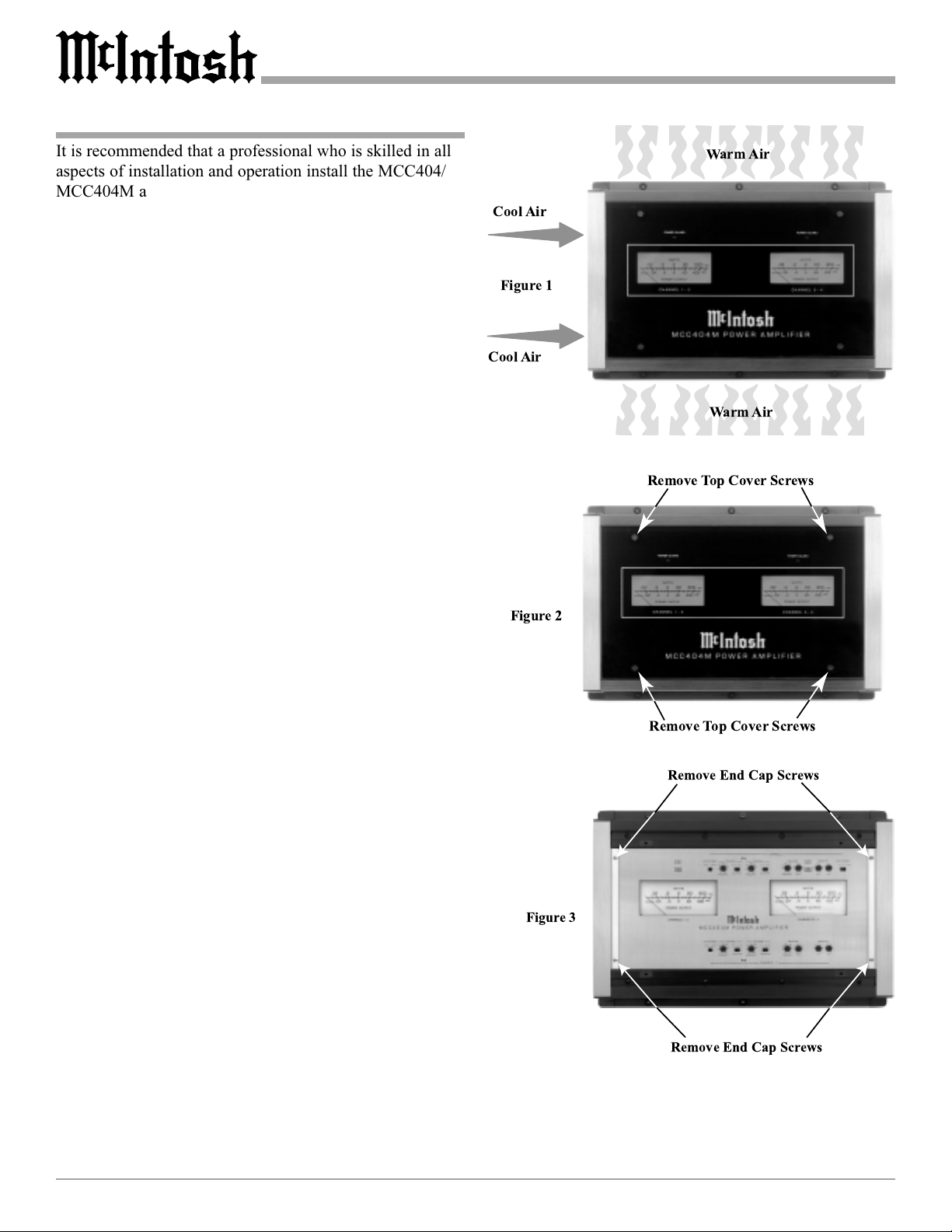
It is recommended that a professional who is skilled in all
aspects of installation and operation install the MCC404/
MCC404M and any associated mobile audio equipment.
Amplifier Ventilation
Always provide adequate ventilation for the MCC404/
MCC404M. The amplifier requires an adequate airflow
into the cooling fans, which are located on the left side of
the amplifier. The warm air exits the amplifier through
vents on the heatsinks. See figure 1. Be sure to provide at
least 1-1/2 inches clearance in front of the cooling fans and
1 inch clearance at the sides of the heatsinks.
The cooling fans are controlled by temperature sensors,
attached to the interior of the tunnel. The fans are normally
off. If the program material contains sustained loud passages demanding high power, the fans will turn-on to increase cooling. If cooling is still not sufficient, additional
heating will shut down the amplifier internal power supply
completely and the Power Guard LEDs will light. The fans
will continue to run and once normal temperatures are restored, operation will resume.
The amplifier can be mounted vertically or horizontally
and may be located under a seat if adequate clearance is
available. The preferred installation method is to mount the
amplifier directly to the vehicle main frame using the hardware supplied with the amplifier.
It is not recommended that the amplifier be mounted
under the hood or in a location where it will be directly exposed to the elements. The openings in the fan housings
and heat tunnel vents can allow internal components to be
damaged by exposure to water, chemicals or any form of
road dust or debris.
WarmAir
Cool Air
Figure 1
Cool Air
WarmAir
Remove Top Cover Screws
Figure 2
Remove Top Cover Screws
Remove End Cap Screws
Removing the Glass Panel
To access the MCC404/MCC404M Controls, remove the
glass panel by removing the four hex bolts with the supplied 3/32 hex key. See figure 2. Attach the supplied suction cup to the top center of the glass panel and carefully
raise it high enough to put your hand under. Temporarily
place the removed glass panel in a safe place, remove the
suction cup and save it for future use.
Removing the End Caps
To access the MCC404/MCC404M Connecting Terminal
Blocks, remove the Glass Panel first (the above step) and
then remove the Phillips Screws holding the End Caps on
both sides of the amplifier and lift the end caps off. See figure 3.
6
Figure 3
Remove End Cap Screws
 Loading...