

Page 1
MC 22O5
POWER AMPLIFIER
SERVICE INFORMATION
STARTING WITH SERIAL NO. AX1001
MclNTOSH
LABORATORY
INC.
BINGHAMTON,
NEW
YORK
13903
038-980
Page 2

MC2205
PERFORMANCE LIMITS & RATINGS
PERFORMANCE
Mc Intosh audio power rat i ngs are in accordance with the Federal Trade Commission Regulation of November 4, 1974 concerning power output claims for ampli-
fiers used in home entertainment pro-
ducts.
POWER OUTPUT
STEREO: 200 watts minimum
sine wave continuous average power output, per channel, both channel's operating
into 1 ohm, 2 ohms, 4 ohms,
or 8 ohms load impedance,
which i s:
14.1 volts RMS across 1 ohm
20.0 volts RMS across 2 ohms
28.3 volts RMS across 4 ohms
40.0 volts RMS across 8 ohms
MONO: 400 watts minimum sine
wave continuous average power
output into 0.5 ohm, 1 ohm,
2 ohms, or 4 ohms load impedance, which is:
14.1 volts RMS across 0.5 ohm
20.0 volts RMS across 1 ohm
28.3 volts RMS across 2 ohms
40.0 volts RMS across 4 ohms
MONO: 0.1% maximum harmonic
distortion at any power level from 250 milliwatts to
400 watts from 20 Hz to
20,000 Hz
INTERMODULATION DISTORTION
STEREO: 0.1% maximum if instantaneous
peak power output is 400 watts or less
per channel with both channels operating for any comb i nat ion of frequencies,
20 Hz to
MONO: 0.1% maximum if instantaneous
peak power output is 800 watts or less
for any combination of frequencies,
20 Hz to 20,000 Hz
20,000
Hz
FREQUENCY RESPONSE
(at one watt output)
20 Hz to 20,000 Hz, +0 -0.25 dB
10 Hz to 100,000 Hz +0 -3.0 dB
NOISE AND HUM
95 dB below rated output
RATINGS
OUTPUT VOLTAGES
OUTPUT LOAD IMPEDANCE
STEREO: 1 ohm, 2 ohms, 4 ohms,
and 8 ohms; separate terminals
are provided for each output
MONO: 0.5 ohm, 1 ohm, 2 ohms,
and 4 ohms; obtained by con-
necting together the appro-
priate terminals of both chan-
nel s
RATED POWER BAND
20 Hz to 20,000 Hz
TOTAL HARMONIC DISTORTION
STEREO: 0.1% maximum harmon-
ic distortion at any power
level from 250 milliwatts to
200 watts per channel from
20 Hz to 20,000 Hz, both
channels operat ing
25 volts for distribution lines
DAMPING FACTOR
STEREO: 16 at I ohm output, 50 at 2
ohms output, 30 at 4 ohms output,
16 at 8 ohms output
MONO: 16 at 0.5 ohms, 50 at 1 ohm,
30 at 2 ohms, and 16 at 4 ohms
output
INPUT IMPEDANCE
100,000 ohms
INPUT SENSITIVITY
Switchable: 0.75 volt or 2.5 voltsLevel control provided for higher
input voltages
POWER REQUIREMENTS
120 volts 50/60HZ, 70 to 550 watts.
Page 3
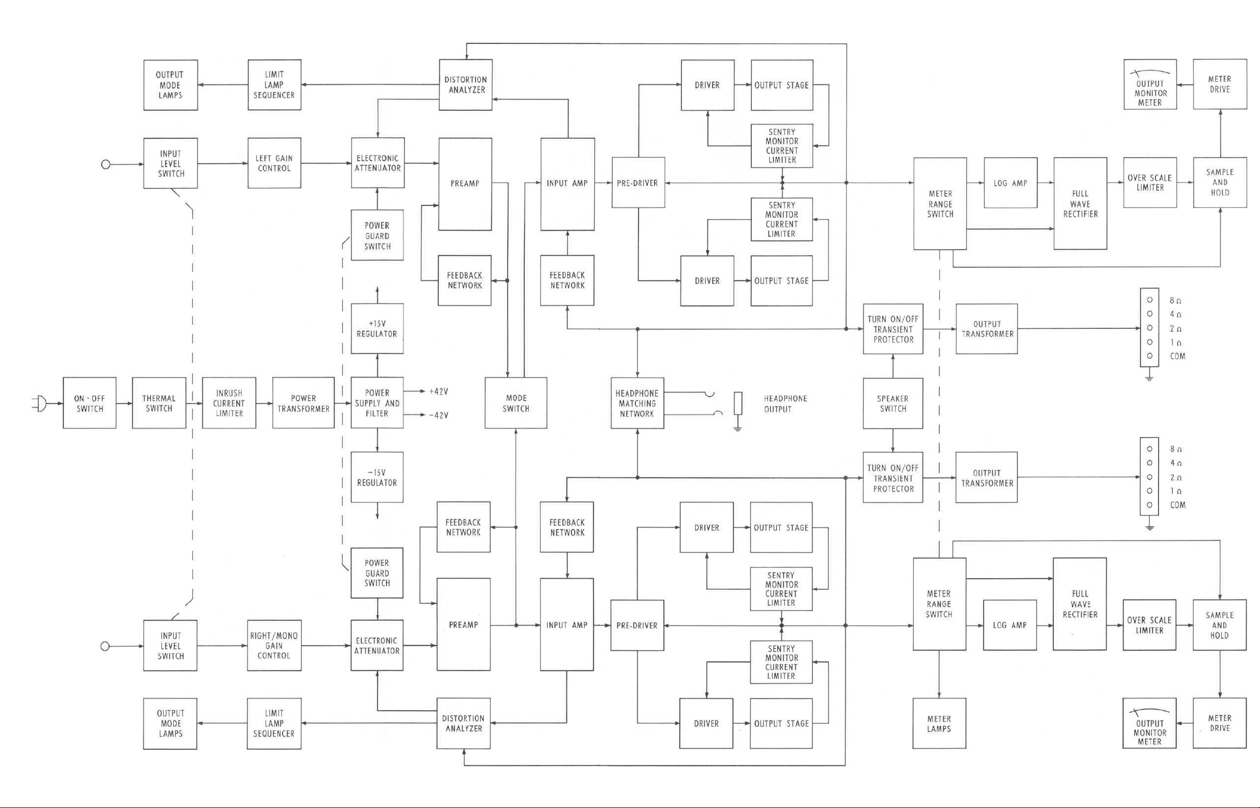
LEFT INPUT
MC2205
LEFT
SPEAKER
OUTPUT
AC
LINE
RIGHT
SPEAKER
OUTPUT
RIGHT/MONO
INPUT
BLOCK DIAGRAM
Page 4
LEFT
CHANNEL
OUTPUT
HEADPHONE
LEFT INPUT
RIGHT/MONO
INPUT
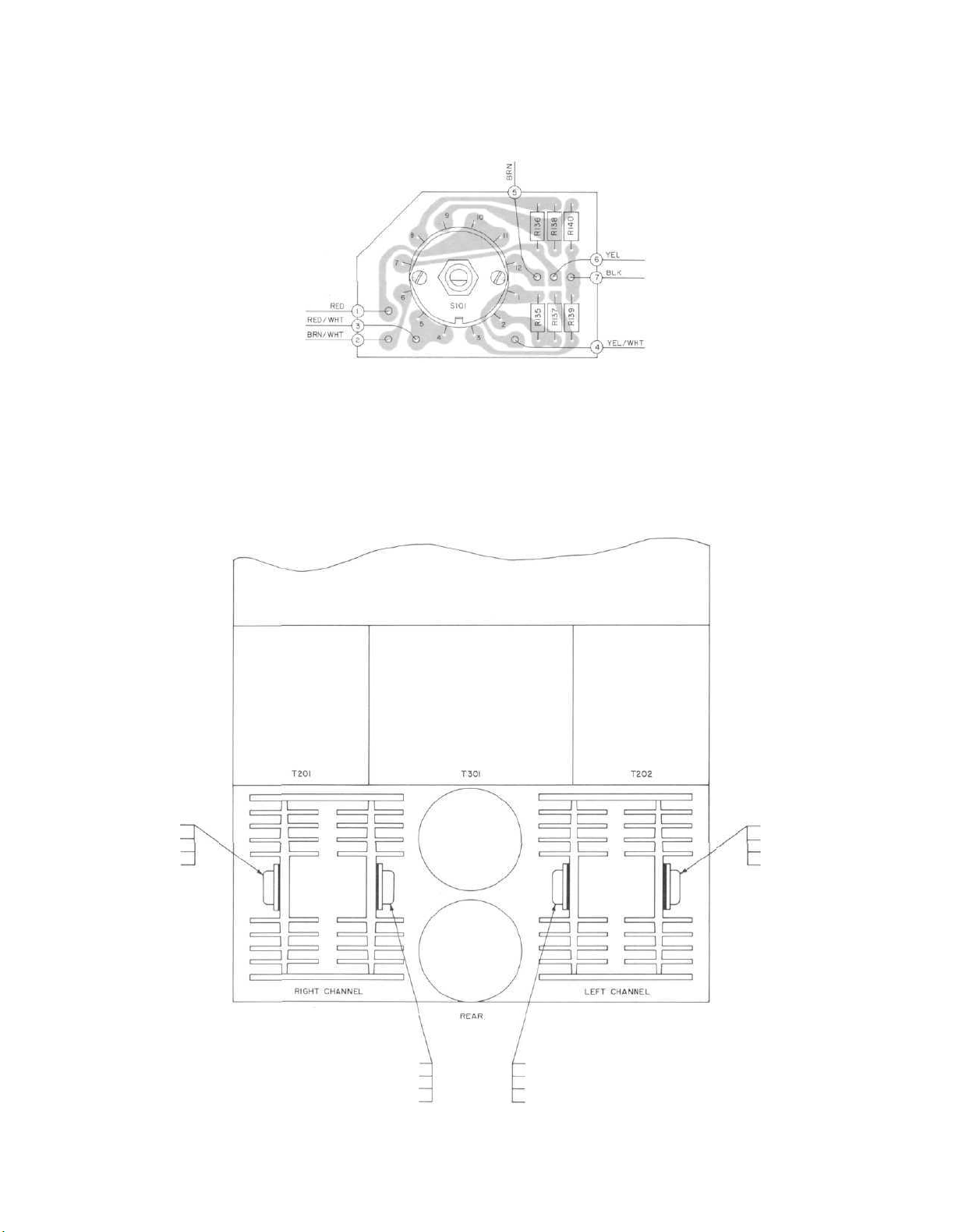
INTERCONNECTION
Page 5

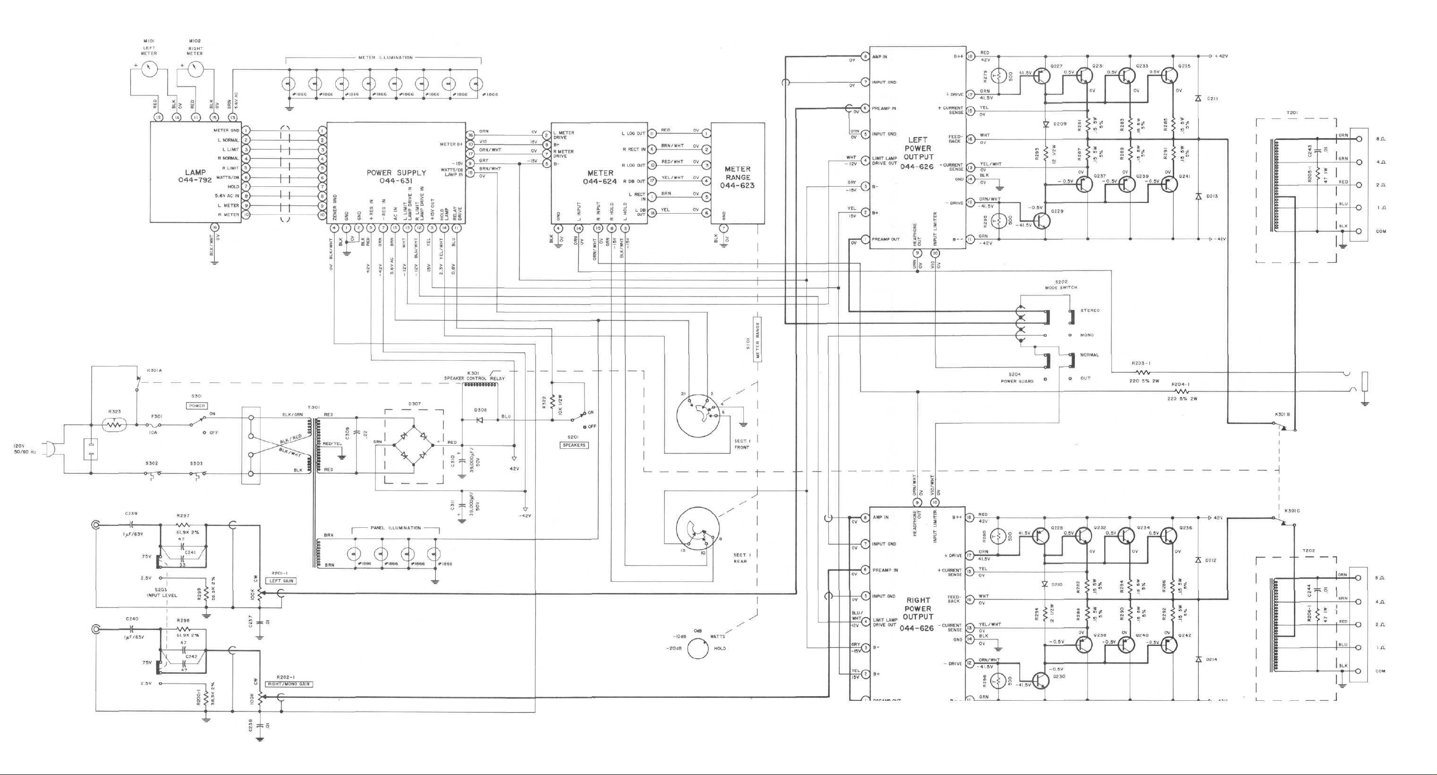
SCHEMATIC NOTES
1.
Unless otherwise
capacitance values sma llr than 1 a re in microfarads (µF) : capacitance values greater
than 1 are in picofarads (pF); inductors are in microhenries (µH).
2 . Printed circuit board components a re ou t1i ned on the schema tics by dotted lines. The
c i rcled numbers on the dotted lines correspond to the numbers on the PC board layouts.
3. The heavy li nes on the schema tics denote the pr ima ry signal path.
4. The terminal number ing of rotary switches is for reference only.
5. All voltages i nd i cated on the schemat i cs a re measu red under the fo11owi ng cond i t i ons;
a. Use of an 11 megohm impedance VTVM.
b. All voltages ± 10% with respect to chassis ground.
c. No signal at input terminals.
d. AC
input
e. Front pane l con t rols at: Rear panel swi tches a t:
Left Gain FULLY CCW Input Level 0.75V
Meter Range WATTS Mode S tereo
Right/Mono Gain FULLY CCW Power Guard Normal
Speakers ON
Power ON
6. Relay K301 shown in energized pos i t i on.
7. Meter adjustments:
Amplifier
into 8 ohm loads with 1 KHz input signal.
a. Set METER RANGE switch to WATTS.
b. Adj us t pot en t i ometer R125 on meter board for a reading of 200 watts on the left meter.
c. Adjust R126 for a reading of 200 watts on the right meter.
d. Set METER RANGE switch to 0 dB
e. Adjust potenti ometer R105 on meter board for a reading of 0 on the DECIBEL scale of the
f. Adjust RI06 for a reading of 0 on the right meter.
must
left meter.
spec
ified:
at 120
volts
be
working properly
Resistance values
AC,
50/60Hz.
to
adjust meters.
are in
ohms,
Ope
1/4
rate
amplifier
watt,
and 10% to
at
full
power
1erance;
MC2205
(40V rms)
8. Power amplifier bias adjustment:
Operate
(approximately 50 watts) or current (approximately O.4 amps). The bias potentiometers R241 &
R242 are located on the power output PC boards.
MC
2205
at 120
volts
line
input
with
no
input
signal.
Measure
the
input
power
a. Turn both bias potentiometers f u l l ccw
b.
Rotate
i
ncrease
bias
then
ad jus
back
tment
off
cw to the
slightly
point
to the
where
point
the
line
where
the
input
line
power
in put
or
current
reaches
begins
its l
owest
va l ue .
c . Repeat step b for each channel independently.
to
Page 6
MC2205
METER
RANGE
PC
BOARD
044-623
Q242
Q240
Q238
Q230
TOP
BOTTOM
Q236
Q234
Q232
Q228
TOP
BOTTOM
Q235
Q233
Q231
Q227
TOP
BOTTOM
LOCATION OF TRANSISTORS NOT ON PC BOARD
Q241
Q239
Q237
Q229
TOP
BOTTOM
Page 7

MC2205
METER RANGE
SWITCH IS SHOWN FRONT VIEW
PC
BOARD
IN WATTS POSITION
044-623
METER RANGE
Page 8

MC2205
LAMP
PC
BOARD
044-792
Page 9

LAMP
PC
BOARD
MC2205
044-792
LAMP
Page 10

MC2205
METER
PC
BOARD
044-624
Page 11

METER
Page 12

MC2205
POWER SUPPLY
Page 13

MC2205
POWER SUPPLY PC BOARD 044-631
Page 14

MC2205
LEFT
CHANNEL
POWER
OUTPUT
PC
BOARD
044-626
Page 15

POWER OUTPUT
Page 16

MC2205
POWER OUTPUT
Page 17

MC2205
RIGHT CHANNEL
POWER
OUTPUT
PC
BOARD
044-626
Page 18

MC2205
REPLACEMENT PARTS
All parts
able f r om
Rep l a cement pa rts may be obta i ned when
by PART NUMBER from:
Symbol
Number
C1O1
, 102
C109,
C1 13, 114
Cl 15
Cl 18
C201 ,202
C203,204
C207,208
C213,214
C215,216
C219,220
C227,228
C229,230
C231 ,232
C233,234
C235,236
C239,240
C301
C305,306
C307,308
C309
C310,31 1
D101
, 102
D
103,
D
105,
D
107,
D
109,
D111,112
D113,1 14
Dl 15, 1 16
D117,1 18
D119
D120
not
listed
radio parts jobbers.
Mclntosh Laboratory, Inc.
Customer Service Department
2 Chambers Street
Binghamton, New York 13903
(telephone 607-723-3512)
Elect 10µF 35V
1 10
Mylar 1 .5µF 1 00V
Elect 10µF 50V
Elect 22µF 35V
Elect 47µF 16V
Elect 10µF 50V
Elect .47µF 50V
Elect 10µF 35V
Elect lO^F 35V
Elect .47µF 50V
Elect 220µF 1 6V
Mylar .0047µF 100V
Poly .01µF 2.5% 63V
Mylar .068µF 1 00V
Poly .01µF 2.5% 63V
Mylar .0047µF 1 00V
Elect 1µF 63V
Elect 10µF 50V
Elect 100µF 16V
Elect 2200µF 1 6V
Mylar .22µF 630V
Elect 39000µF 50V
are
common i tems
CAPACITORS
Descr i pt i on
DIODES
Si. si gna l d i ode
104
106
108
1 10
Si. si gna l d i ode
St. si gna l d iode
Si. si gna l d i ode
Si. si gna l d i ode
Si. si gna l d i ode
Si. si gna l d i ode
Si. si gna l d iode
Si. si gna l d i ode
Zener diode
S i . rect i f i er
obta i n-
ordered
Part
Number
066-173
064-143
066-221
066-214
066-182
066-221
066-244
066-173
066-173
066-244
066-218
064-132
064-142
064-136
064-142
064-132
066-248
066-221
066-226
066-247
064-052
066-225
070-047
070-047
070-047
070-047
070-047
070-047
070-047
070-047
070-047
070-085
070-031
D201 ,202
D203,204
D205.206
D207,208
D209,210
D21 1
,212
0213,214
D215,216
D217,218
D301
D302,303
D304,305
D306
D307
D308
F301
M101
, 102
Q101
, 102
Q103,
104
Q105
Q201 ,202
Q203,204
Q205,206
Q209,210
Q21 1
,212
Q213,214
Q215,216
Q217,218
Q219.220
Q221
,222
Q223,224
Q225,226
Q227,228
Q229,230
Q231 ,232
Q233,234
Q235,236
Q237,238
Q239,240
Si. si gna l d i ode
Si. si gna l d i ode
Si. si gna l d i ode
Si. si gna l d i ode
S i . rect i f i er
S i , rect i f i er
S i . rect i f ier
Si. si gna l d i ode
Si. si gna l d i ode
Si. si gna l d i ode
Si. si gna l d i ode
Zener d i ode 1 6V
Zener d i ode 1 6V
Rect i f i er br i dge
S i . rect i f i er
FUSES
Fuse 10A
METERS
Meter (power level )
TRANSISTORS
S i . NPN trans i stor
S i . PNP trans i stor
S i . NPN trans i stor
Si . NPN transistor
S i . PNP trans istor
Dual
NPN
trans i stor
S i . PNP trans i stor
S i . PNP trans istor
S i . NPN trans-i stor
S i . NPN trans i stor
S i . PNP trans i stor
S i . PNP trans i stor
S i . NPN trans i stor
S i . NPN trans i stor
S i . PNP trans i stor
S i . PNP trans i stor
S i . NPN transistor
Si . NPN transistor
S i . NPN trans i stor
S i . NPN trans i stor
S i . PNP trans i stor
S i . PNP trans i stor
070-047
070-047
070-047
070-047
070-031
070-031
070-031
070-047
070-047
070-047
070-031
070-089
070-089
070-050
070-031
089-034
124-026
132-092
132-096
132-092
132-093
132-096
132-155
132-096
132-096
132-149
132-093
132-148
132-150
132-143
132-136
132-147
132-151
132-152
132-164
132-164
132-164
132-165
132-165
Page 19

MC2205
Q241 ,242
Q301
Q302
Q303
Q304
Q305
Q306
Q307
Q308
IC101
, 102
IC
103,
104
IC105,106
IC201 ,202
R105,
106
R125, 126
R241 ,242
R201-1,202-1
S i , PNP trans i stor
S i . NPN trans i stor
S i . NPN trans i stor
Power t rans i stor
S i . PNP trans i stor
S i . NPN trans i stor
S i . NPN trans i stor
Si . NPN transistor
S i . NPN trans i stor
INTEGRATED CIRCUITS
I ntegrated c i rcu i t
I n tegrated c i rcu i t
I ntegra ted c i rcu i t
I ntegrated c i rcu i t
POTENTIOMETERS
dB Adjust
Log Adjust
Bias Adjust
Ga i n control s
132-165
132-090
132-078
132-079
132-096
132-090
132-143
132-090
132-143
133-037
133-037
133-037
133-037
134-294
134-293
134-298
134-273
S101
S201
S301
S302,303
K301
T201 ,202
T301
SWITCHES
Meter range swi tch
Power on-off swi tch
Speaker sw i tch
Thermal cutout
RELAY
Speaker control
TRANSFORMERS
Output transformer
Power transformer
FRONT PANEL & TRIM
Front panel
Front pane l end caps
Knobs (al l control s)
LAMPS
#1866 Panel & meters
#7382
Normal & limit
#7381 Hold, dB & watts
146-180
146-167
146-167
153-017
087-017
044-636
044-637
044-634
018-173
090-156
058-014
058-061
058-062
R135,136
R137,138
R
139,
140
R141
, 142
R229,230
R249,250
R251 ,252
R255,256
R257,258
R279,280
R281 ,282
R283,284
R285,286
R287,288
R289,290
R291 ,292
R295,296
R297,298
R299
R323
R200-1
R203-1,204-1
RESISTORS
Fi 1m 2.49K 2% 1 /4W
Film
649R
Fi 1m 274R 2% 1 /4W
Thermi s tor
Fi 1m 365n 1% 1/4W
Film
909R
Film 82. 5R 1% 1/4W
Fi 1m 82.5R 1% 1/4W
Film
909R
Thermistor
W i rewound . 1 5R 5W
W i rewound . 1 5R 5W
W i rewound . 1 5R 5W
W i rewound . 1 5R 5W
W i rewound . 1 5R 5W
W i rewound . 1 5R 5W
Therm i stor
Fi 1m 61 .9K 2%
Film 38. 3K 2% 1/4W
Thermi s tor
Film 38. 3K 2% 1 /4W
Wirewound 220R 2W
2%
1/4W
1%
1/4W
1% 1 /4W
1/4W
144-049
144-050
144-048
144-075
144-071
144-073
144-072
144-072
144-073
144-074
139-105
139-105
139-105
139-105
139-105
139-105
144-074
144-077
144-076
144-012
144-076
139-076
PANLOC SYSTEM
Shelf bracket (right)
Shelf bracket ( left)
Mounting template #300
Hardware package
MISCELLANEOUS ITEMS
Plast ic feet
Sh i pp i ng carton
Owners manua l
Line cord
Fuse hol der ,
043-678
043-679
038-244
044-871
017-218
045-008
038-950
170-021
178-001
Page 20

MC2205
038-980
BE072003
15C1105S7-M6980-3
 Loading...