

Page 1
Mclntosh engineering has advanced power amplifier
technology and performance five times since 1949. Experience
and knowledge are the foundation on which the
engineering superstructure is built that supports
the fact that Mclntosh is recognized as Laboratory
Standard for the world. A new level of
technology and atigher level of amplifier performance is realized in the NEW
MC 2205 Power Amplifier.
BIPOLAR EPITAXIAL
RESEARCH AND
TRANSISTOR TECHNOLOGY
• Mclntosh life testing of components permits component selection for trouble-free performance;
added care in production engineering and manufacturing results in long product life
HAS PRODUCED
MclNTOSH
• Mclntosh engineers developed a unique output
stage circuit arrangement that is completely
temperature accurate that delivers clean output
power at any level without crossover distortion
• Mclntosh POWER GUARD assures maximum amplifier power without
clipping distortion
• Mclntosh Output Autotransformer delivers full power output and multiple
feedback loops assure lowest distortion at all power levels and all
speaker impedances
• Mclntosh designed turn on/mute circuits provide positive protection from "turn-on transients"
and other potentially
damaging noises
AMPLIFIER PERFORMANCE
NEW ADVANCES
STARTLING
SUPERIOR
IN SAFE
COOL
Shown in optional
walnut veneer cabinet
MC
2205
Page 2
Higher power demands on amplifiers
have presented music listeners with a
form of unplesantness in listening,
amplifier overload (hard clipping) that
looks and acts like square waves. Clipping
is caused when the amplifier is asked to
produce more power output with low
distortion than it can deliver. Clipping of a
complex wave form is largely composed of
odd order harmonics and intermodulation
products. High order odd harmonics and
intermodulation products are dissonant
and are not musically related to the signal
being amplified. They are heard as great
and disappointing discordance and
distortion.
In the past years Mclntosh has
substantially improved the ability of
amplifiers to deliver lower distortion
within their rated power. The
improvement has removed the masking
of the unpleasant, harshly distorted
sounds of clipping. Music demands high
peak power reproduction ability without
clipping.
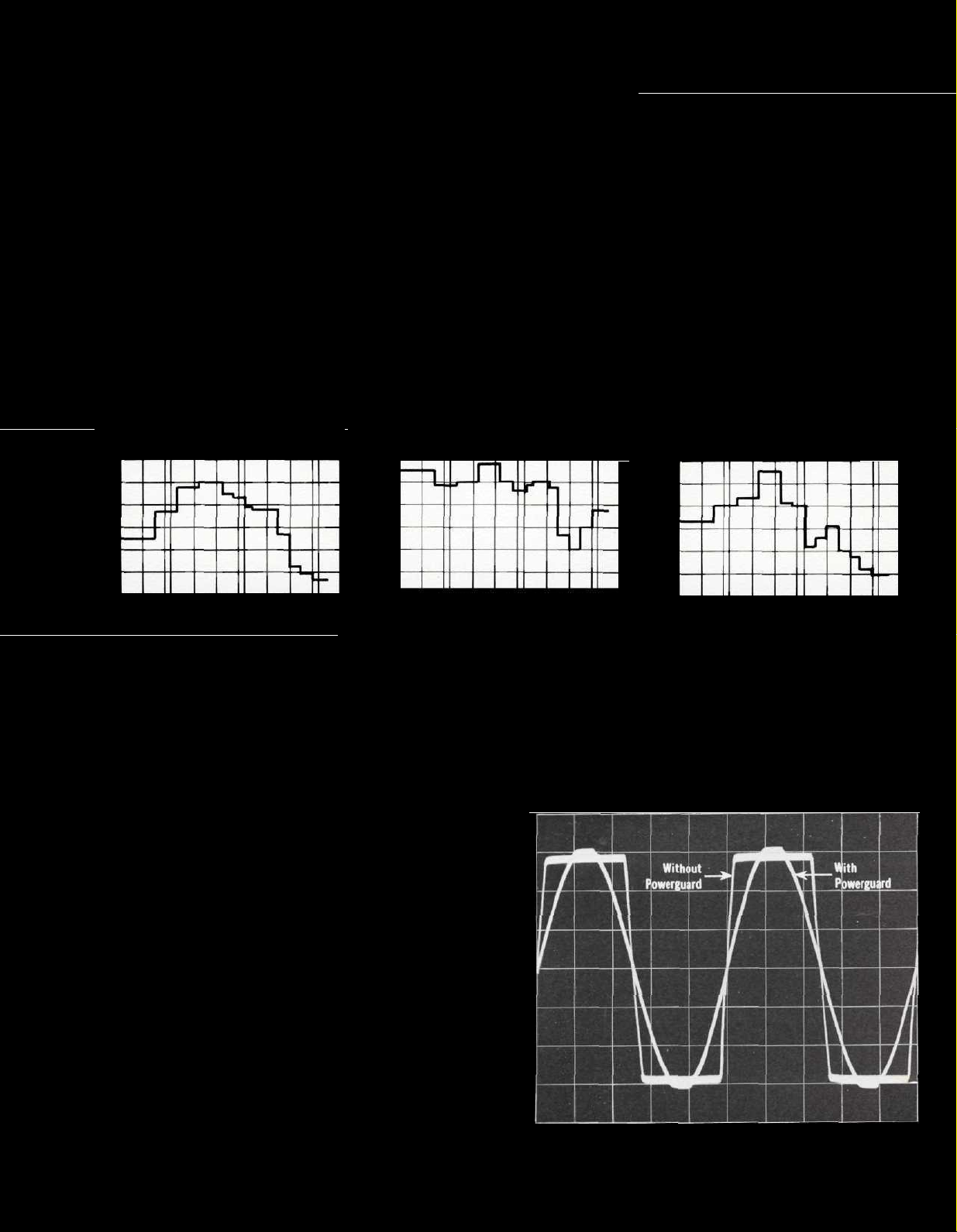
Although we may listen to surprisingly
low average power output, the peak power
requirements can be very high. Consider
these graphs of the power demanded of an
amplifier reproducing the pipe organ, the
piano, and the bass saxophone. The charts
show that the peak power demands is
almost 30 dB or 1000 times the average
power demand. Since it is necessary that
these short interval power spikes be
reproduced with low distortion, it means
the average power output of the power
amplifier must be limited to l/1000th of
its capability or the listener must accept
the discordant distortion of clipping.
2.0 PIANO 10 FT.
30
IN dB
AVERAGE
TO
0
PEAK
PRESSURE
OF
TOTAL
RATIO
-30
20 100 1K 10K
FREQUENCY IN HERTZ
DISTANCE
2.1 PIPE ORGAN 12 FT.
30
0
-30
20 100 1K 10K
.
Amplifiers when driven to clipping are capable of delivering
up to twice the heat load to the loudspeaker. In addition, they
can have more than 40% harmonic distortion. The extra heat
energy content of the clipped signal will damage most speakers. Mclntosh leadership in engineering has developed a new
circuit that ... (1) dynamically prevents power amplifiers
from being overdriven into hard clipping ... (2) which reduces
the heat developed in the loudspeakers ... (3) assures that the
amplifier will produce its maximum output without increased
distortion. That new circuit we call "POWER GUARD."
FREQUENCY IN HERTZ
causing a waveform difference of 0.5% in the output the indicators change from green NORMAL to red LIMIT automatically
and instantaneously. You are always assured that the power
of your amplifier is as clean and distortion free as it can be.
DISTANCE
4.1 BASS SAXOPHONE
30
0
-30
20 100 1K 10K
FREQUENCY IN HERTZ
DISTANCE
3.5 FT.
HOW POWER GUARD WORKS
In Power Guard, a waveform comparison circuit detects
minute amounts of waveform difference between the output
signal and the input signal. A sampling of the program material
at the output of the amplifier is constantly compared with the
program material at the amplifier input. You are alerted, by a
front panel indicator, to waveform differences of 0.5%. Should
the differences reach 1%, Power Guard goes to work. Power
Guard dynamically reduces input level to prevent amplifier
overload yet permits the amplifier to deliver its absolute maxi-
mum power output without extra distortion.
In addition, the output of the "waveform comparator"
activates the front panel NORMAL and LIMIT indicators. Any
time that the input circuit is fed excessive amounts of signal
Oscillogram of output waveform with and without Power Guard. Input
overdriven for each trace 20 dB.
Page 3

Mclntosh developed output monitoring meters add to your
operating ability. The meters are unusually flexible in that
they read directly in watts, can be made to hold the highest
reading and continuously update on higher power or can be
switched to be peak reading — peak locking decibel meters.
When used as a watt meter all the information is direct
reading, without conversions or complicated mathematics.
In addition, as direct reading watt meters they are calibrated
in average watts for a sine wave signal but respond to signal
peaks.
Ordinary meters are incapable of indicating the short in-
terval information in a sound wave. The mass of the meter
movement is too great to respond to the nearly instantaneous
changes in music program material. That short interval information can have a duration as short as one-half of one thousandth of a second. Should the meter be capable of the high
velocity movement the human eye could not perceive the
information.
Mclntosh engineering pursued both problems electrically.
By developing new electronic circuits the meters are made
to respond to short intervals with an accuracy of 98%! To
permit the eye to see such high speed motion the electronic
circuits that drive the meter pointer are time stretched so
the meter pointer position can register in the persistence of
vision characteristics of the human eye.
To achieve long trouble free life in an amplifier it is essen-
tial to have cool operation. Cool operation is the result of
careful design of the output circuit. Correct matching of the
output circuit to the loudspeakers with an autotransformer
and a mechanical layout that uses generous sized, adequately
ventilated heat sinks complete the design for cool operation.
The use of bipolar expitaxial output transistors in the Mc-
lntosh output circuit allows the amplifier to operate as cool
as possible. The predriver, driver, and output stages are fully
complementary and have high circuit efficiency which mini-
mizes heating. Additionally, when there is no signal output
no output transistor is conducting." When there is no signal
no output device is conducting. Conservative Mclntosh engineering keeps operating temperatures low assuring long life.
12
10
8
6
4
amps
2
in
0
current
-2
-4
Output
-6
-8
-10
-12
-100
-90 -80 -70 -60 -50 -40 -30 -20 -10 0 10 20 30 40 50 60 70 80 90 100
characteristics at 8 ohm output of MC 2205
Output volts
Load
and
limiting
The interleaved multifiler wound Mclntosh designed autotransformer transfers all the power you paid for to all impedance taps. You are not power penalized for operating at
an output impedance of less than 8 ohms. The Mclntosh autotransformer does its outstanding job without adding phase
shift, (common in other designs) limiting frequency response
or power output. In short, the Mclntosh autotransformer is
the ideal answer to a difficult problem.
Heat sinks must be large and they must have adequate
ventilation for proper cooling. The MC 2205 has 1100 square
inches (7.64 square feet) of radiating surface. In addition,
the chassis has been designed to permit the maximum amount
of air to flow over the heat sinks to conduct away the life
limiting heat.
With the Mclntosh MC 2205 power amplifier you are Mclntosh protected in five ways
1. The patented Mclntosh Sentry Monitoring
circuit constantly monitors the output signal.
At signal levels up to rated output this circuit
has high impedance and has no effect upon
the output. If the power output exceeds design
maximum, the Sentry Monitoring circuit
operates to limit the signal to the output
transistors. In the event of a short circuit
across the amplifier output or severe
impedance mismatch the Sentry Monitoring
circuit wilt protect the output transistors from
failure. Both positive and negative halves of
the output signal are monitored independently.
2. Should the temperature of the heat sinks
rise above normal through restricted
ventilation or other causes, the AC is
disconnected from the amplifier by an
automatic heat sensing relay. The AC will be
restored when the temperature returns to
normal.
3. Any DC component in the output circuit
from whatever cause is shunted to ground
through the Mclntosh autotransformer. You
and your speakers are protected completely
from this kind of amplifier failure.
4. Mclntosh gives you a money back guarantee
of performance. Your Mclntosh instrument
must be capable of meeting its published
performance limits or you get your money
back. No other manufacturer offers you this
money back guarantee of performance.
5. The famous Mclntosh 3 Year Service
Contract protects you from any cost of repair
for three full years because Mclntosh will
provide all parts, materials and labor needed
to return the measured performance to the
original performance limits free of any charge.
The SERVICE CONTRACT does not cover any
shipping costs to and from the authorized
service agency or the factory.
Page 4

MC 2205 PERFORMANCE LIMITS
Performance Limits are the maximum deviation from perfection permitted for
PERFORMANCE GUARANTEE
a Mclntosh instrument. We promise you that the MC 2205 you buy must be capable of performance at or exceeding these limits or you get your money back.
Mclntosh is the only manufacturer that makes this guarantee.
PERFORMANCE
Mclntosh audio power ratings are in accordance with the Federal Trade Commission Regulation of November 4, 1974 concerning power output claims for
amplifiers used in home entertainment products.
POWER OUTPUT
STEREO
200 watts minimum sine wave continuous average power output, per channel, both channels
operating into 1 ohm, 2 ohms, 4 ohms, or 8
ohms load impedance, which is:
14.1 volts RMS across 1 ohm
20.0 volts RMS across 2 ohms
28.3 volts RMS across 4 ohms
40.0 volts RMS across 8 ohms
MONO
400 watts minimum sine wave continuous average power output into 0.5 ohm, 1 ohm, 2 ohms,
or 4 ohms load impedance, which is:
14.1 volts RMS across 0.5 ohm
20.0 volts RMS across 1 ohm
28.3 volts RMS across 2 ohms
40.0 volts RMS across 4 ohms
OUTPUT LOAD IMPEDANCE
STEREO
1 ohm, 2 ohms, 4 ohms, and 8 ohms; separate
terminals are provided for each output
MONO
0.5 ohm, 1 ohm, 2 ohms, and 4 ohms; obtained
by connecting together the appropriate terminals of both channels
RATED POWER BAND
20 Hz to 20,000 Hz
TOTAL HARMONIC DISTORTION
STEREO
0.1% maximum harmonic distortion at any
power level from 250 milliwatts to 200 watts
per channel from 20 Hz to 20,000 Hz, both
channels operating
MONO
0.1% maximum harmonic distortion at any
power level from 250 milliwatts to 400 watts
from 20 Hz to 20,000 Hz
INTERMODULATION DISTORTION
STEREO
0.1% maximum if instantaneous peak power output is 400 watts or less per channel
with both channels operating for any combination of frequencies, 20 Hz to 20,000
Hz
MONO
0.1% maximum if instantaneous peak power output is 800 watts or less for any
combination of frequencies, 20 Hz to 20.000 Hz
FREQUENCY RESPONSE (at one watt output)
20 Hz to 20,000 Hz, +0 -0.25 dB
10 Hz to 100,000 Hz +0 -3.0 dB
NOISE AND HUM
95 dB below rated output
RATINGS
OUTPUT VOLTAGES
25 volts for distribution lines
DAMPING FACTOR
STEREO
16 at 1 ohm output, 50 at 2 ohms output, 30 at 4 ohms output, 16 at 8 ohms
output
MONO
16 at 0.5 ohms, 50 at 1 ohm, 30 at 2 ohms, and 16 at 4 ohms output
INPUT IMPEDANCE
100,000 ohms
INPUT SENSITIVITY
Switchable: 0.75 volt or 2.5 volts—Level control provided for higher input voltages
GENERAL INFORMATION
POWER REQUIREMENTS
120 volts 50/60 Hz, 50 watts at zero signal output. 750 watts at rated output
SEMICONDUCTOR COMPLEMENT
49 silicon transistors
45 silicon rectifiers and diodes
8 integrated circuits
MECHANICAL INFORMATION
SIZE
Front panel measures 16 3/16 inches wide (41.12 cm) by 7 1/8 inches high
(18. cm). Chassis measures 15 inches wide (38.1 cm) by 6 9/16 inches high
(16.67 cm) by 14 1/2 inches deep (36.83 cm), including connectors. Knob
clearance required is 1 1/2 inches (3.81 cm) in front of mounting panel
FINISH
Front panel is anodized gold and black with special gold/teal nomenclature
illumination. Chassis is chrome and black
WEIGHT
85 pounds (38.6 kg) net, 97 pounds (44.0 kg) in shipping carton
Franchised Dealer:
039-017
2 Chambers St., Binghamton, N.Y. 13903
Phone area 607 723-3512
Design subject to change without notice. Printed in U.S.A.
 Loading...