

Page 1
McIntosh Laboratory, Inc. 2 Chambers Street Binghamton, New York 13903-2699 Phone: 607-723-3512 www.mcintoshlabs.com
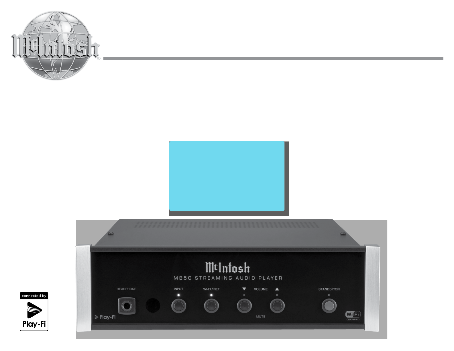
MB50
Streaming Audio Player
Owner’s Manual
Page 2
The lightning ash with arrowhead, within an equilateral triangle,
ATTENTION:
RISQUE DE CHOC ELECTRIQUE - NE PAS OUVRIR
is intended to alert the user to the presence of uninsulated “dangerous voltage” within the product’s enclosure that may be of suf-
cient magnitude to constitute a risk of electric shock to persons.
WARNING - TO REDUCE RISK OF
FIRE OR ELECTRICAL SHOCK, DO
NOT EXPOSE THIS EQUIPMENT TO
RAIN OR MOISTURE.
NO USER-SERVICEABLE PARTS INSIDE. RE-
FER SERVICING TO QUALIFIED PERSONNEL.
The exclamation point within an equilateral triangle is intended to
alert the user to the presence of important operating and maintenance (servicing) instructions in the literature accompanying the
appliance.
To prevent the risk of electric shock,
do not remove cover or back. No
user-serviceable parts inside.
IMPORTANT SAFETY
INSTRUCTIONS!
PLEASE READ THEM BEFORE
OPERATING THIS EQUIPMENT.
1. Read these instructions.
2. Keep these instructions.
3. Heed all warnings.
4. Follow all instructions.
5. Do not use this apparatus near water.
6. Clean only with a dry cloth.
7. Do not block any ventilation openings. Install in accordance with the manufacturer’s instructions.
8. Do not install near any heat sources such as radiators,
heat registers, stoves, or other apparatus (including
ampliers) that produce heat.
9. Do not defeat the safety purpose of the polarized or
grounding-type plug. A polarized plug has two blades
with one wider than the other. A grounding type plug
has two blades and a third grounding prong. The wide
blade or the third prong are provided for your safety. If
the provided plug does not t into your outlet, consult
an electrician for replacement of the obsolete outlet.
10. Protect the power cord from being walked on or pinched
particularly at plugs, convenience receptacles, and the
point where they exit from the apparatus.
11. Only use attachments/accessories specied by the manufacturer.
12. Use only with the cart, stand, tripod, bracket,
or table specied by the manufacturer, or
sold with the apparatus. When a cart is used,
2
use caution when moving the cart/apparatus combination to avoid injury from tip-over.
13. Unplug this apparatus during lightning storms or when
unused for long periods of time.
14. Refer all servicing to qualied service personnel. Servicing is required when the apparatus has been damaged in any way, such as power-supply cord or plug is
damaged, liquid has been spilled or objects have fallen
into the apparatus, the apparatus has been exposed to
rain or moisture, does not operate normally, or has been
dropped.
15. Do not expose this equipment to dripping or splashing
and ensure that no objects lled with liquids, such as
vases, are placed on the equipment.
Ne pas exposer cet appareil à des éclaboussures ou
gouttelettes d’un liquide. Aucun objet remplie de
liquide comme par exemple un vase ne doit être placé
sur l’appareil.
16. If this equipment is supplied with a power supply cord
only, the mains plug of the power supply cord shall
remain readily operable. To completely disconnect this
equipment from the a.c. mains remove the plug from
the a.c. receptacle.
Si l’équipement est uniquement alimenté par un cordon
d’alimentation, la che du cordon d’alimentation doit
demeurer aisément accessible. Pour déconnecter
complètement l’équipement du réseau d’alimentation,
déconnecter la che du cordon d’alimentation de la
prise murale.
17. If this equipment is supplied with AC /DC Adapter with
separate power supply cord or the AC/DC Adapter
plugging directly into an a.c. receptacle, they shall
remain readily operable. To completely disconnect this
equipment from the a.c. mains remove the AC /DC
Adapter mains power supply cord from the a.c. receptacle or remove the AC /DC Adapter when it is directly
plugged into the a.c. receptacle.
Si l’équipement est alimenté par un adaptateur AC/DC
munis d’un cordon d’alimentation ou un adaptateur
AC/DC qui est alimenté directement à la prise murale, ils doivent demeurer aisément accessibles. Pour
déconnecter complètement l’équipement du réseau
d’alimentation, déconnecter l’adaptateur AC/DC de la
prise murale ou déconnecter le cordon d’alimentation
de l’adaptateur AC/DC de la prise murale.
18. WARNING: Do not expose batteries or battery pack to
excessive heat such as sunshine, re or the like.
AVERTISSEMENT: Les batteries ou bloc de batteries
ne doivent pas etre exposees a une chaleur excessive
telle que celle du soleil, feu ou autre source de chaleur
similaire.
19. CAUTION: danger of explosion if battery is incorrectly
replaced. Replace only with the same or equivalent
type.
ATTENTION: danger d’explosion si la pile n’est pas
remplacée correctement. Ne remplacer que par le même
type ou un type équivalent.
20. Connect mains power supply cord only to a mains
socket outlet with a protective earthing connection.
Page 3
Trademark and License Information
FCC INFORMATION (For US and Canada Customers)
a) User Information acc. to FCC15.21 as following:
Changes or modications not expressly approved by the party re-
sponsible for compliance could void the user’s authority to operate
the equipment.
b) Statement for Class B digital device acc. to FCC 15.105 as
following:
NOTE: This equipment has been tested and found to comply
with the limits for a Class A/B digital device, pursuant
to part 15 of the FCC Rules. These limits are designed
to provide reasonable protection against harmful
interference in a residential installation. This equipment
generates, uses and can radiate radio frequency energy
and, if not installed and used in accordance with the
instructions, may cause harmful interference to radio
communications. However, there is no guarantee that
interference will not occur in a particular installation. If
this equipment does cause harmful interference to radio
or television reception, which can be determined by
turning the equipment off and on, the user is encouraged
to try to correct the interference by one or more of the
following measures:
—Reorient or relocate the receiving antenna.
—Increase the separation between the equipment and
receiver.
—Connect the equipment into an outlet on a circuit
different from that to which the receiver is connected.
—Consult the dealer or an experienced radio/ TV
technician for help.
—This device complies with Industry Canada
licence-exempt RSS standard(s). Operation is
subject to the following two conditions: (1) this
device may not cause interference, and (2) this
device must accept any interference, including
interference that may cause undesired operation of
the device.
Le présent appareil est conforme aux CNR
d’Industrie Canada applicables aux appareils radio
exempts de licence. L’exploitation est autorisée
aux deux conditions suivantes : (1) l’appareil ne
doit pas produire de brouillage, et (2) l’utilisateur
de l’appareil doit accepter tout brouillage
radioélectrique subi, même si le brouillage est
susceptible d’en compromettre le fonctionnement.
c) The device must be kept more than 20 cm from all persons.
Trademark and License Information
The McIntosh MB50 incorporates copyright protected
technology that is protected by U.S. patents and other
Trademark Logo License Information
For DTS patents, see http://patents.dts.com.
Manufactured under license from DTS, Inc. DTS,
Play-Fi, the Symbol, and Play-Fi together in
combination with the Symbol are trademarks
of DTS, Inc.
DTS and Play-Fi are registered trademarks of
DTS, Inc. © DTS, Inc. All Rights Reserved.
The Wi-Fi CERTIFIED Logo is a certication
mark of the Wi-Fi Alliance.
intellectual property rights. The MB50 uses the following Technologies:
3
Page 4

Thank You
Your decision to own this McIntosh MB50 Streaming Audio Player ranks you at the very top among
discriminating music listeners. You now have the best.
The McIntosh dedication to precision performance
assures many years of musical enjoyment.
Please take a short time to read the information in this
guide. We want you to be as familiar as possible with
all the features and functions of your new McIntosh.
Please Take A Moment
The serial number, purchase date and McIntosh Dealer
name are important to you for possible insurance
claim or future service. The spaces below have been
provided for you to record that information:
Serial Number: _______________________________
Purchase Date: _______________________________
Dealer Name: ________________________________
Technical Assistance
If at any time you have questions about your McIntosh
product, contact your McIntosh Dealer who is familiar
with your McIntosh equipment and any other brands
that may be part of your system. If you or your Dealer
wish additional help concerning a suspected problem,
you can receive technical assistance for all McIntosh
products at:
McIntosh Laboratory, Inc.
2 Chambers Street
Binghamton, New York 13903
Phone: 607-723-3512
Fax: 607-724-0549
Customer Service
If it is determined that your McIntosh product is in
need of repair, you can return it to your Dealer. You
can also return it to the McIntosh Laboratory Service
Department. For assistance on factory repair return
procedure, contact the McIntosh Service Department
at:
McIntosh Laboratory, Inc.
2 Chambers Street
Binghamton, New York 13903
Phone: 607-723-3515
Fa x : 6 0 7-723-1917
Table of Contents
Safety Instructions ............................................................... 2
FCC Information, Trademark and License Information ..... 3
Thank You and Please Take a Moment ...............................4
Technical Assistance and Customer Service .......................4
Table of Contents ................................................................. 4
General Information ............................................................ 5
Connector and Cable Information ....................................... 5
Introduction ......................................................................... 6
Performance Features .......................................................... 6
Dimensions .......................................................................... 7
Installation ........................................................................... 8
Rear Panel Connections and AC/DC Adapter .....................9
Connecting to a Preamplifier or A/V Control Center ....... 10
Connecting to a Power Amplifier ...................................... 11
Front Panel Display and Push-buttons .............................. 12
How to use the Remote Control .........................................13
How to Set Up the MB50 for Play-Fi ........................... 14-15
How to Operate the MB50 ............................................ 16 -20
Photos ........................................................................ 21
Specifications ............................................................ 22
Packing Instructions ................................................. 23
Copyright 2016 © by McIntosh Laboratory, Inc.
4
Page 5
General Information, Connector and Cable Information
General Information Connector and Cable Information
1. For additional connection information, refer to the
owner’s manual(s) for any component(s) connected
to the MB50 Streaming Audio Player.
2. For the MB50 to receive streaming audio signals
from a mobile device, a wireless router with Wi-Fi
capabilities is required, in order to facilitate com-
munications between the MB50 and the mobile
device.
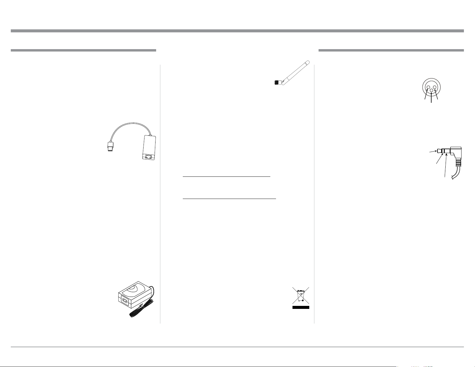
3. When connecting the MB50 to a wired Home
Computer Network (of which
includes a wireless router) a
USB (2.0) to Ethernet (RJ45)
Adapter such as a Monoprice
(109466) is required.
4. The MB50 internal Digital
Circuitry is designed for 2-channel PCM (Pulse
Code Modulation) Digital Audio Signals.
5. The MB50 is designed to be compatible with the
majority of Audio Power Amplifiers. However, do
to a wide range of Power Amplifier Designs, it is
important the input sensitivity of the amplifier be
at least 2 Volts. This will assure music recordings
are reproduced with adequate dynamic range. This
will assure the playback of most music recordings are reproduced with adequate dynamic range.
Check with your McIntosh Dealer for additional
information.
6. If it should become necessary to replace the supplied AC / DC Power Adapter, for use in North
America order part number
75190800. The Power Adapter for
use in other countries, order part
number 75177200. Both Power
Adapters are available from the
McIntosh Parts Department.
7. For proper wireless operation the MB50 requires
connection of both WLAN Anten-
nas. If it should become necessary
to replace one of the supplied Antennas, order part number 12245600
from the McIntosh Parts Department.
8. The performance of the MB50 is dependent upon
the speed and operational range of the Wireless
Router used.
9. When the MB50 is connected to a wired Home
Computer Network with a Wireless Router, the
speed should be 1 Gigabit or faster.
10. The Play-Fi App for Streaming Music and Remote
Control Operation of the MB50 is available at
Web Sites for download free of charge:
For Apple Powered Mobile Devices:
https://itunes.apple.com/us/app/play-fi/
id779245456?mt=8
For Android Powered Mobile Devices:
https://play.google.com/store/apps/details?id=com.
phorus.playf i&hl...
11. When there is an update to the Play-Fi App used
by the MB50, new functionality may be added.
Information about the new functionality would not
be covered in this edition of the MB50 Owners
Manual. Please refer to the Play-Fi Web Site and
the McIntosh Web Site for updated information:
https://www.play-fi.com - (Knowledge Base)
http://www.mcintoshlabs.com - (Products)
12. When discarding the unit, comply with local rules
or regulations. Batteries should never be
thrown away or incinerated but disposed
of in accordance with the local regulations
concerning battery disposal.
13. Periodically, check the McIntosh Web Site at
www.mcintoshlabs.com for the latest information
on the MB50 and other McIntosh Products.
XLR Connectors
Below is the Pin configuration for the XLR Balanced
Output Connectors on the MB50. Refer to the diagram
for connection:
PIN 1: Shield/Ground
PIN 2: + Output
PIN 3: - Output
PIN 1
Power Control Connector
The Trigger Input Jack receives Power On/Off Signals
(+12 volt/0 volt) when connected to other McIntosh
Components. The Trigger Output
Jack sends Power On/Off Signals
(+12 volt/0 volt) when connected
to other McIntosh Components.
Power
Control
Meter
Illumination
Control
Pass Thru
An additional connection is for
controlling the illumination of the Power Output Meters on McIntosh Power Amplifiers. A 3.5mm stereo
mini phone plug is used for connection to the Power
Control Jacks.
PIN 2
Ground
5
Page 6
Introduction
The McIntosh MB50 Streaming Audio Player offers
the latest in audio technology, providing state of the
art audio reproduction from your Audio Mobile and
other Devices. When the MB50 is added to a McIntosh System, the music from this source may be
enjoyed in your home. The advanced design ensures
many years of smooth trouble free operation.
Introduction and Performance Features
• Digital Audio Inputs and Outputs
There are Coaxial and Optical Digital Audio Inputs
and Outputs for connection to other components.
• Unbalanced Analog Inputs and Outputs
The MB50 has both unbalanced Inputs and Outputs
for compatibility with a wide range of audio components.
Performance Features
• Built-in Networking Capability
The MB50 has the ability to connect to an existing
network for connecting to other devices such as NAS
Storage Devices.
• Critical Listening Mode
Retains the original quality of High Resolution Audio
Files up to 96kHz/24 bit, while streaming the music
via Play-Fi. The Critical Listening Mode removes any
Wi-Fi Artifacts like Network Jitter.
• Line In Streaming
The MB50 has the ability to stream the audio from the
selected Audio Input (Digital or Analog) via the PlayFi App to Wireless Loudspeaker Systems, such as the
McIntosh RS100, located in another room.
• Internet Streaming Radio
The MB50 also allows for listening to Internet Radio
Stations when connected to a mobile device using the
Play-Fi App.
• Local AM/FM Radio Stations
The MB50 also allows for listening to local AM/FM
Stations via the Internet when connected to a mobile
device using the Play-Fi App.
• Balanced Analog Outputs
The MB50 has Balanced Outputs which permit long
cable lengths without a loss in sound quality.
• Trigger Control
The Trigger Control Input connection provides conve-
nient Turn-On/Off of the MB50 when connected to a
McIntosh System with Power Control.
• Remote Control
The Remote Control provides operation of the MB50
operating functions when using contemporary components.
• Fiber Optic Solid State Front Panel Illumination
The even Illumination of the Front Panel is accomplished by the combination of custom designed Fiber
Optic Light Diffusers and extra long life Light Emitting Diodes (LEDs).
• Glass Front Panel and Super Mirror Chassis
Finish
The famous McIntosh Illuminated Glass Front Panel
and the Stainless Steel Chassis with Super Mirror
Finish ensures the pristine beauty of the MB50 will be
retained for many years.
6
Page 7
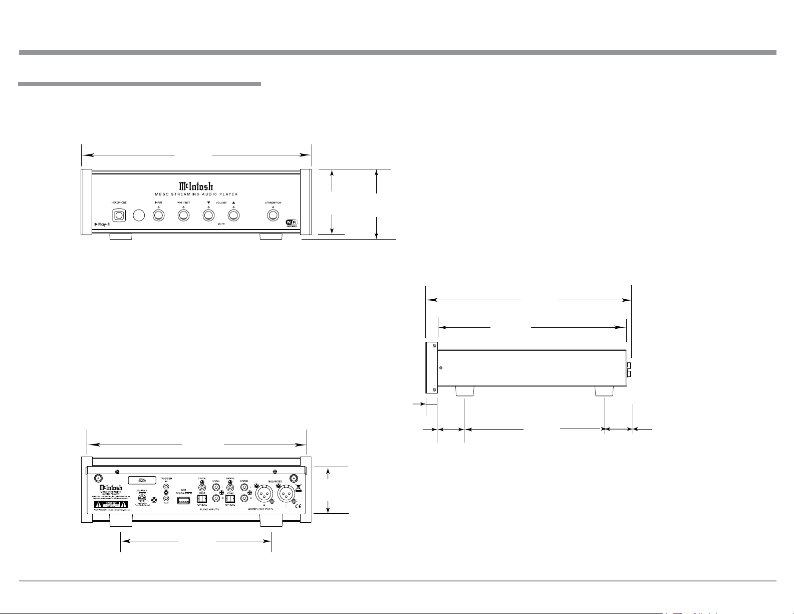
Dimensions
The following dimensions can assist in determining
the best location for your MB50.
Front View of the MB50
11-
1/2"
29.2cm
Dimensions
WLAN ANT 1
Rear View of the MB50
11"
27.9cm
WLAN ANT 2
3-9/32"
8.3cm
2-7/16"
6.2cm
3-25/32"
9.6cm
29/32
1.8cm
"
1-5/8"
4.1cm
Side View of the MB50
13-1/2"
34.3cm
12-7/16"
31.6cm
9"
22.8cm
4-13/16"
12.2cm
7-1/2"
19.0cm
7
Page 8
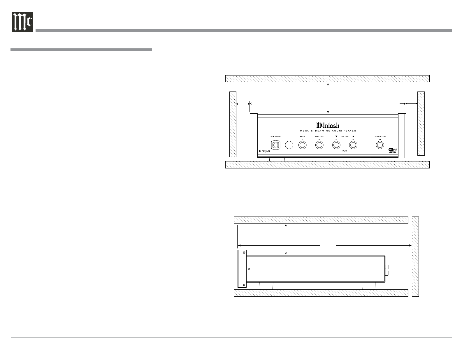
Installation
The MB50 Streaming Audio Player is designed to be
placed upright on a table or shelf, standing on its feet.
The required ventilation requirements are shown.
Always provide adequate ventilation for your MB50.
Cool operation ensures the longest possible operating
life for any electronic instrument. Do not install the
MB50 directly above a heat generating device, such
as a Power Amplifier. Allow at least 1 inch (2.5cm)
above the top, 5/8 inch (1.6cm) below the bottom and 1
inch (2.5cm) on each side of the MB50, so that airflow
is not obstructed. Allow 13-1/2 inches (34.3cm) of
depth for airf low and cable connections.
MB50 Front View
1"
2.5cm
1"
2.5cm
Installation
1"
2.5cm
1"
2.5cm
MB50 Side View
8
13-1/2"
34.3cm
Page 9

Rear Panel Connections and AC/DC Adapter Connections
WLAN 1 (Wireless Local Area Network) ANTenna for receiving Play-Fi
and Wi-Fi signals
The AC/DC Power Adapter supplied
with the MB50 Streaming Audio Player
WLAN ANT 1
USB Connector for
connection to a wired
network via an adapter1
and for service use
BALANCED AUDIO OUTPUTS supply analog audio signals to connect to
Balanced Inputs of other components
COAXial and OPTICAL
DIGITAL AUDIO OUTPUTS
send a Digital Audio Signal to a
Preamplifier or an A/V Control
Center with a D/A Converter or
a decoder
WLAN 2 (Wireless
Local Area Network)
ANTenna for receiving Play-Fi and Wi-Fi
signals
WLAN ANT 2
Connect to the DC IN 5V
connector on the Rear Panel
of the MB50 Streaming
Audio Player
Connect to a live AC outlet (always On)
using the supplied AC Power Cord. Refer to information on the power supply
to determine the correct voltage
Connect the supplied
AC/DC Power Adapter
DC Output Connnector
TRIGGER IN receives turn-on
signals from a McIntosh component
and TRIGGER OUT sends turn-
on signals on to another McIntosh
Component
COAXial and OPTICAL
DIGITAL AUDIO INPUTS
accept a Digital Audio
Signal from a source with
coaxial or optical outputs
UNBALanced AUDIO
OUTPUTS supply analog
audio signals to Unbalanced
Inputs of other components
UNBALanced AUDIO INPUTS
accept high level signals from a
source with an unbalanced output
1
for additional information refer to page 5 “General Infor mation”, number 3
9
Page 10

Connecting to a Preamplifier or A/V
Control Center
Connecting to a Preamplifier or A/V Control Center
The MB50 has the ability to be remotely switched On/
Off from a McIntosh Preamplifier or A/V Control
Center via the Trigger (Power Control) Connection.
The connection instructions below, together with
the MB50 Connection Diagram located on the separate folded sheet “Mc1A”, is an example of a typical audio system. Your system may vary from this,
however the actual components would be connected in
a similar manner. For additional information refer to
“Connector and Cable Information” on page 5.
Trigger (Power Control) Connections:
1. Connect a Control Cable from the Preamplifier
or A/V Control Center Power Control MAIN (or
ACC) Jack to the TRIGGER (Power Control) IN
Jack on the McIntosh MB50 Streaming Audio
Player.
2. Connect a Control Cable from the MB50 TRIGGER OUT Jack to the SACD/CD Transport Power
Control IN.
3. Connect a Control Cable from the SACD/CD
Power Control Out to the AM/FM Tuner Power
Control In.
4. Connect a Control Cable from the AM/FM Tuner
Power Control Out to the Media Bridge Server
Power Control In.
5. Connect any additional components in a similar
manner, as outlined in steps 2 thru 4.
Digital Audio Connections:
6. Connect an Optical Cable from the McIntosh
MB50 DIGITAL AUDIO OPTICAL INPUT to
the Digital Audio Optical Output of the SACD/CD
Player.
7. Connect a Coaxial Cable from the McIntosh
MB50 DIGITAL AUDIO COAXIAL INPUT to
the Digital Audio Coaxial Outputs of the Media
Bridge Server.
10
Analog Audio Connections:
8. Connect Cables from the McIntosh MB50 Streaming Audio Player AUDIO OUTPUT BALANCED
Connectors to the Preamplifier or A/V Control
Center Balanced Input Connectors.
Note: Unbalanced connections may be used instead
of the Balanced Connections.
9. Connect Cables from the McIntosh MB50 UNBALanced AUDIO INPUT to the AM/FM Tuner
Unbalanced Output.
Wired and Wireless Network Connections:
10. Optionally, using an USB to Ethernet Adapter
connect the MB50 USB Connector to the CAT
5/6 Ethernet Cable. Connect the other end of the
CAT 5/6 Ethernet Cable to the Wired Router RJ45
Connector.
11. Connect another CAT 5/6 Ethernet Cable from the
Wired Router to a Wireless Router.
Note: The Wireless Router facilitates communica-
tion and streaming from a mobile device to the
MB50.
12. When the MB50 will be utilizing direct communications with a Wireless Router (no wired
Network Connections), make sure to connect the
supplied WLAN Antennas to the WLAN ANT 1
and WLAN ANT 2 connectors on the MB50 Rear
Panel.
AC Power Cords Connections:
13. Locate the plug at the end of the cable coming out
of the supplied AC/DC Power Supply and connect
it to the DC IN 5V connector on the Rear Panel of
the MB50 Streaming Audio Player.
14. Connect the supplied AC Power Cord between the
socket on the AC/DC Power Supply and a live AC
outlet (that is always On).
Page 11

Connecting to a Power Amplifier
Connecting to a Power Amplifier
The MB50 has the ability to provide a Trigger Output
Signal to remotely switch the Power On/Off to components connected to it via the Trigger (Power Control)
Connection.
The connection instructions below, together with
the MB50 Connection Diagram located on the separate folded sheet “Mc1B”, is an example of a typical audio system. Your system may vary from this,
however the actual components would be connected in
a similar manner. For additional information refer to
“Connector and Cable Information” on page 5.
Trigger (Power Control) Connections:
1. Connect a Control Cable from the MB50 TRIGGER OUT Jack to the SACD/CD Transport Power
Control IN.
2. Connect a Control Cable from the SACD/CD
Power Control Out to the AM/FM Tuner Power
Control In.
3. Connect a Control Cable from the AM/FM Tuner
Power Control Out to the Media Bridge Server
Power Control In.
4. Connect a Control Cable from the Media Bridge
Server Power Control Out Jack to the Power Control In Jack on the Power Amplifier.
5. Connect any additional components in a similar
manner, as outlined in steps 2 thru 4.
Digital Audio Connections:
6. Connect an Optical Cable from the McIntosh
MB50 DIGITAL AUDIO OPTICAL INPUT to
the Digital Audio Optical Output of the SACD/CD
Player.
7. Connect a Coaxial Cable from the McIntosh
MB50 DIGITAL AUDIO COAXIAL INPUT to
the Digital Audio Coaxial Outputs of the Media
Bridge Server.
Analog Audio Connections:
8. Connect Cables from the McIntosh MB50 Streaming Audio Player AUDIO OUTPUT, BALANCED
Connectors to the Power Amplifier Balanced Input
Connectors.
Note: Unbalanced connections may be used instead
of the Balanced Connections.
9. Connect Cables from the McIntosh MB50 UNBALanced AUDIO INPUT to the AM/FM Tuner
Unbalanced Output.
Wired and Wireless Network Connections:
10. Optionally, using an USB to Ethernet Adapter
connect the MB50 USB Connector to the CAT
5/6 Ethernet Cable. Connect the other end of the
CAT 5/6 Ethernet Cable to the Wired Router RJ45
Connector.
11. Connect another CAT 5/6 Ethernet Cable from the
Wired Router to a Wireless Router.
Note: The Wireless Router facilitates communica-
tion and streaming from a mobile device to the
MB50.
12. When the MB50 will be utilizing direct communications with a Wireless Router (no wired
Network Connections), make sure to connect the
supplied WLAN Antennas to the WLAN ANT 1
and WLAN ANT 2 connectors on the MB50 Rear
Panel.
AC Power Cords Connections:
13. Locate the plug at the end of the cable coming out
of the supplied AC/DC Power Supply and connect
it to the DC IN 5V connector on the Rear Panel of
the MB50 Streaming Audio Player.
14. Connect the supplied AC Power Cord between the
socket on the AC/DC Power Supply and a live AC
outlet (that is always On).
11
Page 12

Front Panel Display and Push-buttons
IR Sensor receives commands
from a Remote Control
Indicates by color
which Input has been
selected for listening
Indicates by color and
flashing which Network
has been selected and
communication status
Indicates when minimum
listening level has been
reached and f lashes when
Muting is active
Indicates when maximum
listening level has been
reached and f lashes when
Muting is active
Indicates when the MB50 is in
Standby. It also Indicates the
current operational status
12
Connection for dynamic
type headphones, for
private listening
Select from one of the
various Input Sources
available for listening
Select from one of
the various Network
Sources available for
listening
STANDBY/ON Push-button
switches the MB50 ON or OFF
(Standby) and resets the micro-
processors
Adjusts the listening level for
both channels Up or Down
and also Mutes the sound
Page 13

How to use the Remote Control
The supplied Remote Control performs the various
Operating Functions for the MB50 Streaming Audio
Player.
Notes: 1. Refer to the “How to Operate” Section of
this manual for additional information.
2. The HR079 McIntosh Remote Control is
also supplied with other McIntosh Products.
If the MB50 is connected to a McIntosh
Amplifier (also using the HR079) possible
interaction can occur. To prevent interaction, Remote Control Operation of the MB50
can be switched Off. Refer to “Volume Level
Note” on page 17 for additional information.
Input Source Selection
Press the
gram source.
→ Push-button to select the desired pro-
Tunes Up the Dial with
optional McIntosh Tuner
connected to the MB50
Decreases the volume level
Selects the desired INPUT
How to use the Remote Control
Use to move through the available choices
up, down, left, right; of menu items with an
optional McIntosh Disc Player connected
to the MB50
Tunes Down the Dial with
optional McIntosh Tuner connected to the MB50
Increases the volume level
LED illuminates during the time
a remote command is sent to the
MB50
Volume
Press the + or - Push-button to increase or decrease the listening level.
Mute
Press the (Mute) Push-button to mute the audio.
The VOLUME LED indicators will f lash at a slow
rate during the time audio is muted. Press the MUTE
Push-button a second time to resume listening.
Pause
Press the PAUSE
Push-button to temporarily stop
playback of the music.
Mutes and unmutes the audio
Note: Push-buttons whose function is not identified above are for use with other McIntosh Products.
Powers the MB50 ON or OFF
Activates the PLAYBACK ► of
a track
Used to PAUSE Playback of the
track
13
Page 14

Introduction to Setting Up the MB50
MB50 Quick Start Guide Sheet 3
Your McIntosh MB50 is factory configured for immediate enjoyment of superb audio from source components with Digital or Analog Outputs.
It is highly recommended to contact your McIntosh
Dealer and/or Mobile Device Dealer for assistance
in the installation and configuration of the Wireless
Router and/or the wired network with a Wireless
Router. Your Dealer has the necessary knowledge to
properly set up the MB50 as part of your Home Network wired or wireless.
(for Apple Powered Devices)
To utilize the MB50 Play-Fi feature (for streaming
music from your mobile device), it is necessary to first
establish Wi-Fi (wireless) communications between
the MB50 and the mobile device.
STEP 9
ESTABLISH COMMUNICATIONS WITH THE MB50
1st - POWER ON THE MB50
2nd - GREEN LED INDICATES WHEN THE MB50 IS IN THE
SETUP MODE, FOR ESTABLISHING WIRELESS OR
WIRED NETWORK CONNECTIONS
3rd - SELECT
“Play-Fi APP”
4th - SELECT “Set-up New Device”
NOTE: Proceed with “Set-up new De-
vice” after the “WI-FI/NET” LED
rapidly to slowly pulsing On/Off.
Proceed to
STEP 10 on
next page
14
5th - SELECT
“Settings”
6th - SELECT
“Wi-Fi”
7th - LOCATES
Play-Fi Device
(MB50)
Figu re 1
8th - Setting Up communications
with MB50
9th - Communications
established with
MB50
Page 15

How to Setup the MB50 for Play-Fi
MB50 Quick Start Guide Sheet 6
The MB50 Quick Start Guide (located on the supplied separate folded sheets) will aid in establishing
the communications between the MB50, your Mobile
Device and the Network/Wireless Router. Figures 1
STEP 13
2nd - GREEN LED INDICATES WHEN THE MB50 IS IN THE
SETUP MODE, FOR ESTABLISHING WIRELESS OR
WIRED NETWORK CONNECTIONS
ESTABLISH COMMUNICATIONS WITH THE MB50
1st - POWER ON THE MB50
and 2 are sample illustrations from the MB50 Quick
Start Guide for Apple and Android Powered Mobile
Devices. After communications have been established,
proceed to page 16 “How to Operate the MB50”.
(for Android Powered Devices)
Searching for Play-Fi Devices
Searching for Play-Fi Devices
3rd - SELECT
“Play-Fi APP”
4th - SELECT “Set-up New Device”
NOTE: Proceed with “Set-up new Device” after the
“WI-FI/NET” LED indicator changes from
5th - ENTER
“Network
(Router)
Password”
6th - SELECT
“Next”
7th - SELECT the name of
the room where the
MB50 is located
Figu re 2
8th - SELECT “Location Name”
NOTE: The “WI-FI/NET” LED
indicator will change
from slowly pulsing On/
Off to On all the time.
9th - SELECT “Music”
to start playback of
desired music
REFER TO THE MB50
OWNER’S MANUAL
PAGES 10 and 11
FOR CONNECTION
OF ADDITIONAL
EQUIPMENT TO THE
MB50 FOR LISTENING
IF HEADPHONES
ARE THE PRIMARY
LISTENING METHOD,
PLEASE REFER TO
PAGE 16 “HOW TO
OPERATE” SECTION
OF THE MB50 OWNER’S MANUAL
15
Page 16

How to Operate the MB50
Your McIntosh MB50 is factory configured for immediate enjoyment of superb audio from a Mobile Device
via Play-Fi or one of the external devices connected to
the Rear Panel of the MB50.
If you wish to make a Play-Fi wireless connection
between the Mobile Device and the MB50, please refer to “Introduction to Setting Up the MB50” on page
14 for additional information.
Power On
Press the ON/STANDBY Push-button on the Front
Panel of the MB50 or press the Power Push-button
on the Remote Control to switch On the MB50. Refer
to figures 30 and 31.
FRONT PANEL STANDBY/ON INDICATOR
MB50
On/Off
Off Red Standby Mode Not connected
Off Orange Sleep Mode Maintains Connection
On Green On Mode Connection if established
Power Mode
The MB50 incorporates an Auto Off Feature, which
automatically places it into the Power Save Mode. This
Color
of LED
Operation Status Network Connection
Status
occurs approximately 2 hours after there has been an
absence of audible audio signals on the selected input
or user activity (includes changes to any of the Operation Functions such as Input selection, Volume adjust-
ment, etc). It also allows for choosing between if the
Network Connection (Sleep Mode) is maintained or
the Network Connection (Standby Mode) becomes ac-
tive thus terminating the Network Connection. If it is
desired to enable the Auto Off Feature perform either
of the following:
Auto Off with Network Sleep Mode Disabled:
1. Press and hold simultaneously the Wi-Fi/NET
and VOLUME ▼ (Down) Push-buttons until the
Front Panel Display Wi-Fi/NET LED Indicator
changes color from Green to Red. Then release the
two Push-buttons. The Power Save Mode is now
Disabled.
2. To Enable the Power Save Mode repeat step 1 and
the Wi-Fi/NET LED Indicator will change color
from Red to Green.
Auto Off with Network Standby Mode Enabled:
1. Press and hold simultaneously the STANDBY/
ON and VOLUME ▲ (Up) Push-buttons until the
Front Panel Display Wi-Fi/NET LED Indicator
changes color from Green to Red. Then release the
two Push-buttons. The Power Save Mode is now
Disabled.
2. To Enable the Power Save Mode repeat step 1 and
the Wi-Fi/NET LED Indicator will change color
from Red to Green.
Network Sleep Mode
The Network Sleep Mode is Enabled by default. With
the Sleep Mode active, the MB50 will automatically
switch On when the Mobile Device Play-Fi App
is started and the assigned name (for the MB50) is
selected. When the MB50 is connected to AC Power
for the first time (or if a Reset to Factory Default Settings is performed) its operational status is “Standby
Mode”. After switching AC Power first On to the
MB50 the Operation Status will automatically change
to the “Sleep Mode” when it is switched Off. To place
the MB50 in Standby Mode for just the current time
(Sleep Mode Disabled), perform the following step:
1. With the MB50 On, press and hold the STANDBY/
ON Push-buttons until the Front Panel STANDBY/
ON LED Indicator changes color from Green to
a flashing Red. Then release the STANDBY/ON
Push-button. When the MB50 has completed the
change, the MB50 will swtich Off and the Front
Panel STANDBY/ON LED Indicator color is a
constant Red. The MB50 is now in the Standby
Mode.
The next time the MB50 is switched On the Network
Sleep Mode will automaticaly re-activate.
16
Source Selection
To select the desired audio source, press the INPUT
Push-button on the Front Panel of the MB50 or press
Figu re 30
Page 17

How to Operate the MB50
→ (Input) Push-button on the Remote Control
the
until the desired source is selected. Refer to figures 30
and 31.
MB50 Inputs
Music Source Indicator Color
Wi-Fi - Play-Fi Mobile Device
NET - Play-Fi over the Network
COAX - Digital coaxial connection
to an external source
OPTICAL - Digital optical connection
to an external source
UNBAL - Analog stereo connection
to an external source
Note: The Mobile Device will disconnect when switch-
ing to another Input Source on the MB50.
Green
Red
White
Blue
Volume Level
To increase the Volume Level, press the Front Panel
VOLUME ▲ (Up) Push-button or the VOLUME +
Push-button on the Remote Control to increase the
volume to the desired level. The LED indicator above
the Front Panel VOLUME ▲ (Up) Push-button will
illuminate continuously during the increase of Volume
Level. When the maximum volume level is reached,
the LED will flash rapidly.
To decrease the Volume Level press the Front Panel
VOLUME ▼ (Down) Push-button or the VOLUME
- Push-button on the Remote Control. The LED
indicator above the Front Panel VOLUME ▼ (Down)
will illuminate continuously during the decrease of
Volume Level. When the minimum volume level is
reached the LED will flash rapidly. Refer to figure 30
and 31.
Note: When the MB50 is connected to an existing Audio
System (or Audio/Video System) with a Preamplifier, it may be desirable to use the System Volume
Control to adjust the listening volume level when
the MB50 is the selected music source. To change
the MB50 from a variable output volume to a
fixed output volume level, perform the following
steps:
1. Select the desired MB50 Music Source.
2. Using the MB50 Volume Push-buttons
adjust the listening level to be at the same
relative listening level as when other inputs on the Audio System (or Audio/Video
System) are selected.
3. Using the Front Panel INPUT and VOLUME ▼ (Down) Push-buttons, press and
hold them in until the Illumination of the
Front Panel nomenclature switches Off,
then release both Push-buttons.
4. The MB50 Output Volume Level is now
fixed, Remote Control Operation of the
MB50 is switched Off and Input Source
Selection is now performed by using the
Front Panel INPUT Push-button.
To return the
MB50 to a variable VOLUME
adjustment of the
listening level
and to reactivate
Remote Control
Operation, repeat
step 3.
Mute
To mute the volume level, simultaneously press
the VOLUME ▼(Down)
and ▲(Up) Push-buttons
on the Front Panel of
the MB50 or press the
Mute Push-button on the
Remote Control. Dur-
Fig u r e 31
ing the time the sound is muted the Volume LEDs on
the Front Panel will flash at a slow rate. To unmute
and return to the previous volume level, simultane-
ously press the VOLUME ▼(Down) and ▲(Up)
Push-buttons on the Front panel or press the Mute
Push-button on the Remote Control. Pressing either
the VOLUME ▼(Down) or ▲(Up) Push-button on the
Front Panel or the VOLUME - or + on the Remote
Control will also un-Mute the MB50. Refer to figure
30 and 31.
Play-Fi
For Mobile Device specific operating information
(Apple or Andriod) go to the Play-Fi web site at
https://play-f i.com/
Notes: 1. If you have questions about the Play-Fi App
and its Operation refer to the Play-Fi “Knowledge Base” for additional information.
2. Some of the Internet Music Streaming Services (available via the Play-Fi App) offer the
listener the ability to alter the sound quality
of music being streamed. Refer to each of the
Music Streaming Services Internet Web Site for
additonal information on how to make changes
to their default settings, if available.
Critical Listening Mode
The Play-Fi App supports the native sound resolution
formats of the music played. When the sound format is
high resolution, the sound is normally down-sampled
to insure proper Wi-Fi Streaming Capability with the
most common wireless network hardware. In the Play-
Fi App there is a Critical Listening Mode which keeps
the original sound resolution up to 96kHz/24Bit. This
requires the MB50 and Mobile Device be connected
by high performance network equipment. To activate
the Critical Listening Mode perform the following
17
Page 18

steps using the Play-Fi App:
1. Select the “Hi RES Audio” Icon. Refer to
figure 32.
Hi RES Audio
Figure 32
2. Referring to figure 33, select the MB50 (in this
example it is the “Living Room”).
Indicates when the MB50 is in
the Critical Listening Mode
Figure 33
3. Select “Music”. Refer to figure 34.
4. The music selection that has the unsupported sam-
Figure 35
ple rate may be listened to by switching Off the
Critical Listening Mode. Switch Off the Critical
Listening Mode by first selecting the “X”. Refer to
figure 36. Then select “OK” in the “Are you sure?
Closing will stop playback” window.
5. Then select the MB50 (Living Room) followed by
selecting “Music”. Refer to figures 37 and 38.
Figure 37
Figu re 38
7. Then select the music. Refer to figure 39.
Figure 34
Note: When a recording is in a sound format not sup-
ported by the Critical Listening Mode, a message will appear stating “This file is encoded
in an unsupported sample rate and cannot be
played”. Refer to figure 35
18
Figu re 36
Figure 39
Page 19

How to Operate the MB50, con’t
Line In Streaming Mode
The MB50 has the ability to stream the audio from the
selected Audio Input (Digital or Analog) via the PlayFi App to Wireless Loudspeaker Systems, such as
the McIntosh RS100, located in another room. In the
following example the MB50 is located in the living
room and in the bedroom a pair of Wireless Powered
Loudspeakers (like the McIntosh RS100). To activate
the Line In Streaming Mode perform the following
steps:
Note: Before proceeding below, it is first important
to setup the Wireless Loudspeakers using the
Play-Fi App either as a single Loudspeaker or
as a Stereo pair. Refer to the information supplied with the Wireless Loudspeaker(s).
1. Start the Play-Fi App on the Mobile Device and
select the “Plus Symbol”. Refer to figure 40.
Select the Plus Symbol
3. Then select the MB50 (Living Room) in the
Line In Window. Refer to gure 42.
Figu re 42
4. Now select the Audio Source Coaxial Input
to be streamed to the Wireless Loudspeakers
located in Bedroom 1. Then select “NEXT”.
Refer to gure 43.
5. The just selected Input (Coaxial) can now
be streamed to the Wireless Loudspeakers
(Bedroom 1) and can also be listened to in the
Living Room (via the MB50). Referring to
gure 44 make the appropriate room selections
followed by selecting “DONE”.
Figu re 44
Figu re 40
2. From the plus menu, select “Line In”. Refer to
fig ure 41.
Figure 41
6. The selected Input (Coaxial) will now be playing in both rooms (Living Room and Bedroom
1). There are three Volume Control Adjustments available, Living Room, Bedroom 1 and
a Master Volume affecting both rooms at the
same time. Refer to gure 45 on the next page.
Figure 43
19
Page 20

How to Operate the MB50, con’t
Line In Streaming Mode, con’t
Figure 45
7. Referring to gure 46, the selection of the
Streaming Source, and what room(s) will be
playing that source may be changed at any
time by selecting “EDIT”. The rst choice
will be to either keep the same source or select
another source. Then select “NEXT” to decide
on the room(s) that will playing music.
Resetting to Factory Default Settings
If it becomes desirable to reset all of the MB50 settings to the factory default values, perform the following steps:
1. With the MB50 On, press and hold in simultaneously the INPUT and STANDBY/ON Push-but-
tons.
2. Release the Push-buttons when the Front Panel
LEDs start flashing.
3. Press the STANDBY/ON Push-button and refer to
page 14 to re-establish communications with your
Mobile Device.
Figure 46
20
Page 21

Photos
21
Page 22

Specications
Audio Specifications Digital Audio Specifications
Frequency Response
+/-0.5dB from 20Hz to 20,000Hz
Total Harmonic Distortion
0.005%
Sensitivity
200mV, UnBalanced
Maximum Input Signal
2Vrms, UnBalanced
Variable Output level
0 - 6.0Vrms Unbalanced
0- 12.0Vrms Balanced
Signal To Noise Ratio (A-Weighted)
100dB
Dynamic Range
98dB
Digital Input Signal Format
Coaxial and Optical Inputs - SPDIF (PCM1)
Digital Input Sample Rate
Coaxial and Optical: 44.1kHz to 192kHz, 24-Bit
Digital Inputs
Coaxial: 0.5V p-p/75 ohms
Optical: - 15dbm to -21dbm (TOS Link)
1
PCM (Pulse Code Modulation) Digital Signal type used for
CD Discs, etc.
Power Control Specications
Power Control Input
5-15VDC, less than 1mA
Power Control Output
12VDC, 25mA maximum total
USB Connector
Output Impedance
Less than 200 ohms (Unbalanced and Balanced)
Type A connector with Host Mode.
Used for firmware Updates and Network Connection
using a special adapter (see page 5, note 3 for addi-
tional information)
General Specifications
Power Requirements
100-240 Volts, 50/60Hz at 10 Watts
Standby: Less than 0.5 watt
Overall Dimensions
Width is 11-1/2 inches (29.2cm)
Height is 3-25/32 inches (9.6cm)
Depth is 15-1/2 inches (39.4cm) including the Front
Panel and connection cables.
Weight
8.5 pounds (3.9Kg) net (includes the external Power
Supply), 9.5 pounds (4.3Kg) in shipping carton
Shipping Carton Dimensions
Width is 16 inches (40.6cm)
Height is 9 inches (22.8cm)
Depth is 17 inches (43.1cm)
22
Wi-Fi Connectivity
IEEE 802.11a/b/g/n ; Wi-Fi (Dual Band).WPS
Page 23

Packing Instructions
In the event it is necessary to repack the equipment for
shipment, the equipment must be packed exactly as
shown below. It is very important that the four plastic feet are attached to the bottom of the equipment.
This will ensure the proper equipment location on the
bottom pad. Failure to do this will result in shipping
damage.
Use the original shipping carton and interior parts
only if they are all in good serviceable condition. If
a shipping carton or any of the interior part(s) are
needed, please call or write Customer Service Department of McIntosh Laboratory. Refer to page 4. Please
see the Part List for the correct part numbers.
Quantity Part Number Description
1 034565 Shipping carton only
2 034566 Side Foam Pad
4 163185 Plastic foot
4 400159 #10-32 x 3/4” screw
4 404080 #10 Flat washer
A.C. Cord and
Wi-Fi Antennas
Side Foam
Pad
Shipping Carton
Packing Instructions
Remote Control
AC/DC Adapter
Side Foam
Pad
23
Page 24

McIntosh Laboratory, Inc.
2 Chambers Street
Binghamton, NY 13903
www.mcintoshlabs.com
The continuous improvement of its products is the policy of McIntosh Laboratory Incorporated who reserve the right to
improve design without notice.
The MB50 is designed to employ non-McIntosh-provided services (including but not limited to Play-Fi
®
Wi-Fi
), some of which require separate customer subscriptions and some of which do not, as part of the Products’
functionality. Because McIntosh cannot control the providers of such services or the services themselves, the owner
of the Product therefore assumes all risks related to the use of services provided by anyone other than McIntosh itself.
McIntosh cannot and does not warrant against, and shall have no liability of any kind for any of the following that are
attributable to non-McIntosh providers or services: (i) interruption, discontinuance, or other unsatisfactory performance
of service; (ii) reduced Product functionality that is so attributable; or (iii) any other loss or damage of any kind that is
so attributable.
®
and
McIntosh Part No. 04166401
 Loading...