

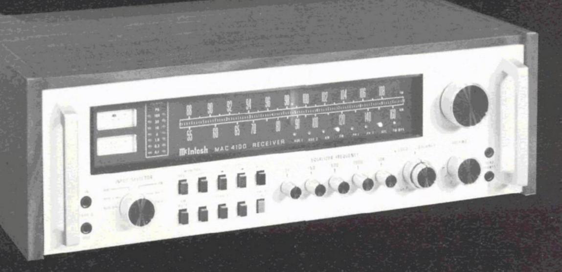
MAC 4100
The MAC 4100 is the most Value Packed Receiver in the world

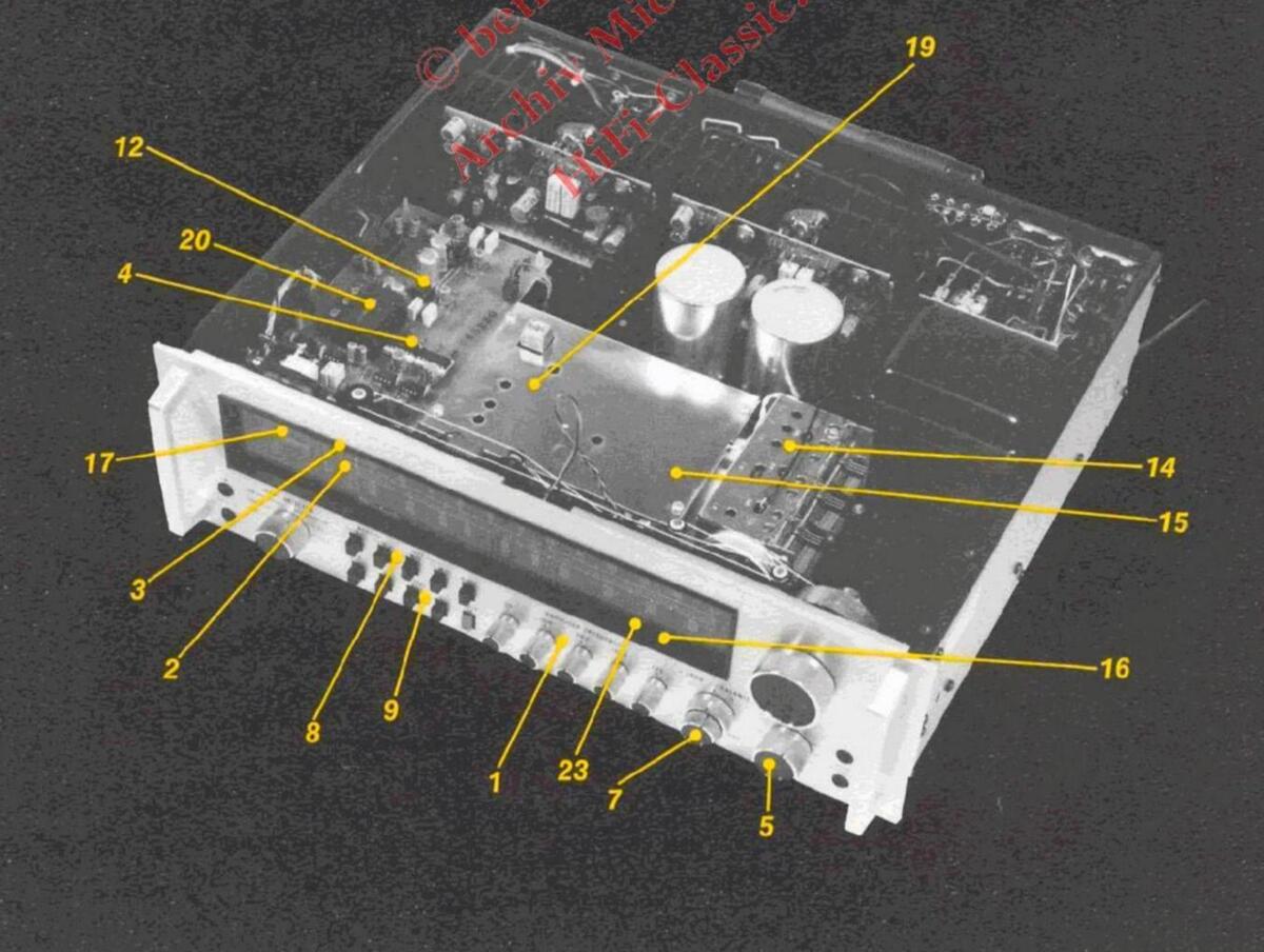
1. FIVE BAND PROGRAM EQUALIZER
Five separate controls allow great flexibility when compensating for program deficiencies.
- "LED" POWER OUTPUT INDICATORS Two columns of seven yellow "LED" indicators provide an indication of the amount of power being fed to your speakers.
- 3. POWER GUARD INDICATOR AND PROTECTION CIRCUIT Two red "LED" power guard indicators indicate when the power amplifier has reached full output. At this point the power guard circuit begins to control amplification dynamically so that you will not hear the harsh distorted sound of square wave clipping. In addition your speakers are protected from burnout.
- ELECTRONIC AUDIO SIGNAL SWITCHING FET analog switches are used to give smooth switching transition from one input to another without clicks and pops.
- 5. SUPER-TRACKING VOLUME CONTROL The volume control is a precision stepped at-
tenuator which has left to right tracking accuracy within 1 dB throughout its entire range. System balance is maintained at all listening levels.
6. LESS THAN 0.05% TOTAL HARMONIC DISTORTION
Harmonic distortion does not exceed 0.05% when measured from the phono input to the speaker output from 20 Hz to 20 kHz at all power levels from 250 mW to full rated output.
7. TRUE VARIABLE LOUDNESS COMPENSATION CONTROL
The loudness control operates independently of the volume control and its contour is accurately modeled after the Fletcher Munson family of "equal loudness" curves.
8. DUAL TAPE MONITOR AND TAPE COPY SWITCHES
Two tape recorders can record simultaneously from the program being listened to or you may record from one to the other without interfering with the "Listen" program.
AC 4100 FEATUR
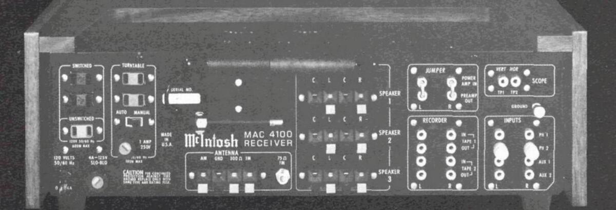
- SPEAKER SWITCHES FOR THREE SETS OF SPEAKERS Three sets of loudspeakers may be used one at a time, two together, or all three simultaneously.
- 10. SPEAKER PROTECTION CIRCUITS Loudspeakers are protected from burnout by the Power Guard circuit and also by other circuits that instantaneously disconnect the speakers in the event of the presence of DC on the output.
- 11. PREAMP OUTPUT POWER AMP INPUT CONNECTIONS Back panel connections provide the ability to insert room equalizers, reverberation units or other signal processing devices.
- 12. LOW NOISE ION-IMPLANTED J-FET OP-AMPS New technology low noise operational amplifiers give lower noise and greater bandwidth than conventional devices.
- 13. ELECTRONIC ACTIVE FILTER ELEMENTS "Active filter" technology is used to generate
the equivalent of the inductors normally used in equalizer filters. This eliminates the hum pickup or inductance non linearity that often occurs from conventional inductors.
14. MOS-FET FM FRONT END
Great signal sensitivity together with freedom from strong signal overload is made possible by using MOS Field Effect Transistors in the FM RF circuits.
15. ULTRA STABLE LINEAR-PHASE PIEZOELECTRIC FM IF FILTERS
The IF filters are permanently sealed and never require adjustment. The IF response curve is extremely selective because of its very steep slope either side of center and yet it has a linear phase characteristic.
16. AUTOMATIC FREQUENCY LOCK
Perfect FM tuning is assured by holding off the tuning lock signal until manual tuning reaches the center of the FM carrier.
24
17. WIDE RANGE SIGNAL STRENGTH METER The signal strength meter pointer responds all

the way from 1 microvolt of antenna noise pickup to over 50,000 microvolts of signal strength. This allows accurate directional antenna orientation.
18. FM TUNER SCOPE PLUG IN CONNECTIONS
An oscilloscope or maximum performance in-dicator may be connected easily to adjust a directional antenna for minimum FM multipath distortion
10 FM MULTIPLEX THIRD GENERATION PLL CIRCUIT
PLL CIRCUIT Tri-level electronic switching in the multiplex decorder gives better separation, lower distor-tion, and superior SCA rejection. Contains tri-level logic for better separation. No inductors required, minimizing drift; Integral lamp driving capability to indicate presence of a 19 kc pilot carrier; Excellent channel separation over the entire audio frequency range; Extremely low distortion; Low output impedance; Transient free mono/stereo switching free mono/stereo switching.
MULTIPLEX PILOT AND CARRIER SUPPRESSION CIRCUIT The 19 kHz pilot and 38 kHz carrier are removed from the output thereby eliminating the possibility of introducing these undesirable signals to the tape recorder input.
21. "AUTO-ON" AC OUTLETS
- SWITCHED AC OUTLETS
- 23. "LED" FUNCTION INDICATORS System status is indicated by long life "LED" indicators
TURN-ON TRANSIENT ELIMINATION CIRCUITS
Speaker outputs are connected only after power supplies and circuits have stabilized eliminating turn on thumps or clicks.
TECHNICAL HIGHLIGHTS
Phono Amplifier The phono amplifier uses a new high technology in-tegrated circuit operational amplifier. Its differential in-put stage has been optimized for low noise and low distortion performance. Open loop gain of this in-tegrated circuit is 100,000. With high open loop gain a large amount of negative feedback can be used around the share amplifier to further reduce noise and distorlarge amount of negative feedback can be used around the phono amplifier to further reduce noise and distor-tion. The feedback network also provides precision RIAA frequency compensation. It uses 1% metal film resistors and 5% poly film capacitors. To achieve low noise performance it is essential that the feedback net-work be very low impedance. As a consequence, the preamplifier must be capable of operating as a power amplifier to drive this impedance. The actual power output capability of this preamplifier stage is more than 100 milliwatts, a great margin beyond that which is required is required
Input Selector Switching Electronic input selector switching uses field effect analog switches. The mechanical input selector simply switches small amounts of DC which turn the FET analog switches off or on. This design eliminates degradation of frequency response and also eliminates noise pickup from long signal paths necessary with conventional mechanical switching. It means, as well, that switch clicks and pops have been eliminated.
Equalizer Amplifier The equalizer amplifier is constructed with ion im-planted junction field effect operational amplifiers. These new devices amplify signals with a 6 dB better signal to noise ratio than their bipolar counterparts. Five other operational amplifiers are each arranged in circuit configurations that are the equivalent of series tuned circuits, one at each of the five center frequen-cies. Each series tuned circuit is inserted via the contuned circuits, one at each of the five center frequen-cies. Each series tuned circuit is inserted via the con-trol potentiometer in either the input circuit or feed-back circuit of the FET op-amp thereby providing a boost and cut capability of 12 dB for each band of fre-quencies. The equalizer amplifier has a gain of 0 dB.
quencies. The equalizer amplifier has a gain of 0 dB. Power Guard Amplifiers are capable of delivering large quantities of power when they are driven to clipping. Clipping is caused when the amplifier is asked to produce more power output than it can deliver with low distortion. A clipped amplifier can have more than 40% harmonic distortion. The extra energy content of the clipped signal will damage most loudspeakers, particularly the delicate high frequency tweeters. A new McIntosh ad-vancement helps protect your speakers from this kind of damage. The MAC 4100 has a built-in waveform com-parator that compares the wave shape of the input signal with the output signal. If the disparity between the two signals exceeds 0.5% (equivalent to 0.5% total harmonic distortion) a front panel signal illuminates in red at the top of the power output indicators. With any further increase in distortion the POWER GUARD cir-cuit will operate. This circuit limits the input dynamically so that the amplifier cannot be overdriven. POWER GUARD eliminates amplifier output clipping. POWER GUARD does not limit the dynamic range or
POWER GUARD eliminates amplifier output clipping. POWER GUARD does not limit the dynamic range or the power output of the power amplifier. Clipping oc-curs when an amplifier runs out of power supply. Since POWER GUARD does not begin to work until this point is reached, the power capability of the amplifier is neveraffected.
FM Section The FM-IF consists of five integrated circuits and four
piezo electric filters. They combine to give a total gain of over 140 dB. The signal is amplified over a million times. The response curve has nearly linear phase times. The response curve has nearly linear phase characteristics. The skirts of the response curve are very steep. The maximum width is 170 kHz at 3 dB and 500 kHz at 60 dB. The response is symmetrical each side of the center frequency. The filters are permanent-ly sealed and never require adjustment. They cannot drift or vibrate out of adjustment. The exceptionally high gain of the five integrated circuits assures hard limiting at very low levels of input signal. A "phase" or "Foster-Seeley" discriminator has been designed to complement the integrated circuit IF sec-tion. The detection output of the discriminator is ex-tremely low in distortion.
FM Stereo Multiplex Section The heart of the multiplex section is a new third generation phase lock loop (PLL) stereo decoder ingeneration phase lock loop (PLL) stereo decoder in-tegrated circuit (IC). This PLL IC incorporates two special systems, an automatic variable separation con-trol circuit to reduce background noise when receiving weak stereo stations, and a tri-level digital waveform generation which eliminates interference from SCA signals and from the sidebands of adjacent channel FM signals.
The variable separation control is operated from the IF amplifier's signal strength detector system. A smooth
The variable separation control is operated from the IF amplifier's signal strength detector system. A smooth transition is provided from mono to stereo or visa versa at weak signal levels to provide the optimum signal to noise ratio and best stereo separation for the prevail-ing signal conditions. The circuit operates only during stereo reception, it switches automatically to monaural if the 19 kHz pilot tone is absent. In the PLL the internal oscillator operates at 228 kHz locked to the 19 kHz pilot tone. The 228 kHz feeds a 3 stage Johnson counter via a binary divider to generate a series of square waves. Suitably connected NAND gates and exclusive OR gates produce the tri-level drive waveform for the various demodulators in the cir-cuit. The usual square waveforms have been replaced in the PLL and decoder sections by tri-level waveforms. These tri-level forms contain no harmonics which are multiples of 2 or 3. This eliminates frequency trans-lation and detection of interference from the side-bands of adjacent stations since the third harmonic of the sub-carrier (114 kHz) is excluded and interference from SCA broadcasts since the third harmonic of the pilot tone (57 kHz) is excluded. Unwanted spurious audible components and phase jitter in the PLL with consequent intermodulation distortion are inherently eliminated by this technique. Additional advantages of the phase locked loop stereo
Additional advantages of the phase locked loop stereo demodulation are the elimination of inductors to minimize drift, integral lamp driving capability to in-dicate the presence of the 19 kHz pilot carrier, ex-cellent channel separation over the entire audio fre-quency range, extremely low distortion, low output im-pedance, and transient-free mono/stereo switching.
After multiplex detection, 19 kHz pilot and 38 kHz car-rier suppression circuits are used to prevent tape recorderinterference.
The FM muting circuit is unusual. It operates both by detecting ultrasonic noise and by sensing correct tun-ing of the detector circuit. To 'un-mute' it is necessary for the signal to have an adequate signal-to-noise ratio and to be tuned to the center of the FM carrier. The MUTING circuit can be activated or defeated by the front panel muting pushbutton. The switching on and off of the audio signal is done with FET analog switches.
MAC 4100 PERFORMANCE LIMITS
Performance limits are the maximum deviation from perfection permitted for-a McIntosh instrument. We promise you that when you purchase a new MAC 4100 from a McIntosh Franchised dealer it will be capable of performance at or exceeding these limits or you can return the unit and get your money back. McIntosh is the only manufacturer that makes this statement.
AMPLIFIER SECTION
POWER OUTPUT
100 watts minimum sine wave continuous average power output, per channel, both channels operating in-to 4 ohms 20 Hz to 20 kHz, with no more than .05% total harmonic distortion 75 watts minimum sine wave continuous average power output, per channel, both channels operating in-to 8 ohms 20 Hz to 20 kHz, with no more than .05% total
harmonic distortion OUTPUT LOAD IMPEDANCE
4 ohms, 8 ohms RATED POWER BAND 20 Hz to 20 kHz TOTAL HARMONIC DISTORTION
.05% maximum at any power level from 250 milliwatts to rated power per channel, 20 Hz to 20 kHz, both change nels operating INTERMODULATION DISTORTION
.05% maximum at any power level from 250 milliwatts to rated power per channel both channels operating for any combination of frequencies 20 Hz to 20 kHz FREQUENCY RESPONSE 20 Hz to 20 kHz +0, -0.5 dB at rated power HUM AND NOISE Power Amp: 100 dB IHFA, 95 dB unweighted, below
rated_output Tape and Aux Input: 95 dB IHFA, 90 dB unweighted below rated output Phono Input: 90 dB IHFA, 80 dB unweighted, below 10
mV input DAMPING FACTOR
DAMPING FACTOR Greater than 30 INPUT SENSITIVITY AND IMPEDANCE Power Amp: 2.5 V; 22,000 ohms Tape and Aux: 250 mV; 100,000 ohms Phono: 2 mV; 47,000 ohms; 87 pF TAPE OUTPUT Tuner: 1.0 V at 100% modulation (FM) Tape: 250 mV with rated input Phono: 250 mV with rated input Phono: 250 mV with rated input PROGRAM EQUALIZER ± 12 dB at 30, 150, 500, 1500, and 10,000 Hz
FRANCHISED DEALER
FM SECTION SENSITIVITY
2mV (11.2 dBF) IHF minimu SIGNAL TO NOISE RATIO
70 dB IHF minimum HARMONIC DISTORTION Mono: 0,18% IHF maximum Stereo: 0.38% IHF maximum FREQUENCY RESPONSE 20 Hz to 15kHz +0, -1 dB CAPTURE RATIO 1.8 dB
1.8 dB SELECTIVITY
SELECTIVITY 75 dB IHF minimum SPURIOUS REJECTION 90 dB IHF minimum IMAGE REJECTION 80 dB IHF minimum STEREO SEPARATION 45 dB minimum at 1 kHz SCA REJECTION 60 dB minimum
AM SECTION
75mVIHF (External antenna) SIGNAL TO NOISE RATIO 45 dB minimum IHF, 55 dB at 100% modulation HARMONIC DISTORTION 0.8% maximum at 30% modulation FREQUENCY RESPONSE
ADJACENT CHANNEL SELECTIVITY
30 dB minimum IHF IMAGE REJECTION 65 B minimum, 540 kHz to 1600 kHz
SEMICONDUCTOR COMPLEMENT 45 Transistors 31 Integrated Circuits 62 Diodes Silicon Controlled Rectifier
MECHANICAL INFORMATION
In cabinet: 18-5/8 inches (473.1mm) wide, 6-1/2 inches (165.1mm) high, 15-1/2 inches (393.7mm) deep. Without cabinet: Front panel measures 17-9/16 inches (446.1mm) wide by 5-1/4 inches (133.4mm) high. Chassis measures 17-1/8 inches (435mm) wide by 4-15/16 inches high (125.4mm) by 13-1/2 inches (342.9mm) deep. Knob and handle clearance required 1-1/16 inches (27mm) in front of the mounting surface. FINISH
Front panel is clear anodized to produce a brushed satin - silver finish with black anodized trim. Cabinet is walnut grained vinyl. WEIGHT
42 pounds (19 kg) net 56 pounds (25.4 kg) in shipping carton
The continuous improvement of its products is the policy of McIntosh Laboratory Incorporated, who reserves the right to improve lesign without notice.
Muntosh
MCINTOSH LABORATORY INC 2 CHAMBERS ST., BINGHAMTON, N.Y. 13903-9990 607-723-3512


 Loading...