

Page 1
INTEGRATED AMPLIFIER
WATTS
2.0
20
-
20
-
10
DECIBELS
TUNER MUTEVIDEO LOUDPH AUX/TAP E
200
0
TREBLEBASS
0
0
4
LEFT RIGHT
SEN SOR
.
02
-
40
CD 2 MONO SPEAKERSCD 1
.
20
-
30
POWER OUTPUT
CONTENTS
Performance Specifications ........................................ 2
Notes ......................................................................... 3
Rear Panel .................................................................. 4
Section Location ........................................................ 4
Block Diagram ...................................................... 5 - 8
Interconnection Diagram .................................... 9 - 10
Input Driver Schematic and PCB ....................... 11 - 18
Heatsink Schematic and PCB ............................ 19 - 20
WATTS
2.0
-
20
DECIBELS
20
200
-
10
0
VOLUME
POWE R GUARD
HEADPHON ES
.
20
.
02
-
30
-
40
POWER OUTPUT
BALANCE
LR
1
2
Lamp Schematic and PCB ................................. 19 - 20
PG Display Schematic and PCB ........................ 21 - 22
Control Schematic and PCB .............................. 21 - 22
Tone Schematic and PCB .................................. 23 - 26
Parts List ............................................................ 25 - 28
Exploded View and Parts List ............................. 29 - 31
Repacking Instructions ............................................. 33
0
0
4
STANDBY ON
/
SERVICE MANUAL
Page 2

PREFORMANCE SPECIFICATIONS
POWER OUTPUT, STEREO
250, 200, 120 watts minimum sine wave continuous
average power output per channel, both channels operating, into a load impedance of 2, 4 and 8 ohms respectively.
TOTAL HARMONIC DISTORTION
0.005% maximum at any power level from 250 milliwatts
to rated power per channel from 20Hz to 20,000Hz, both
channels operating.
INTERMODULATION DISTORTION
0.005% maximum if instantaneous peak power output per
channel does not exceed twice the rated output with both
channels operating for any combination of frequencies
from 20Hz to 20,000Hz.
OUTPUT LOAD IMPEDANCE
2, 4 or 8 ohms
RATED POWER BAND
20Hz to 20,000Hz
DYNAMIC HEADROOM
2.4dB at 2, 4 or 8 ohms
DAMPING FACTOR
60 at 2 ohms
120 at 4 ohms
230 at 8 ohms
FREQUENCY RESPONSE
+0, -0.5dB from 20Hz to 20,000Hz
SIGNAL TO NOISE RATIO, (A WEIGHTED)
Phono Input: 90dB (84dB IHF) below 10mV input
High Level: 100db (90dB IHF) below rated output
Power Amplifier: 110dB below rated output
SENSITIVITY
Phono: 2.5mV for 2.5V rated output (0.5mV IHF)
High Level: 250mV for 2.5V rated output (50mV IHF)
Power Amplifier Input: 2.5V for rated output
INPUT IMPEDANCE
Phono: 47k ohms, 65pF
High Level: 22k ohms
MAXIMUM INPUT SIGNAL
Phono: 90mV
High Level: 8V
POWER REQUIREMENT
120V, 50/60Hz, 5.0 Amps UL/CSA
230V, 50/60Hz, 2.5 Amps
PREAMPLIFIER MAXIMUM VOLTAGE OUTPUT
Phono: 90mV at tape output
High Level: 8V at tape output
Main Out: 8V at preamp output
VOLTAGE GAIN
High Level to Tape: 0dB
High Level to Main: 20dB
TONE CONTROLS
Bass Control: +/-12dB at 20Hz
Treble Control: +/-12dB at 10kHz
POWER REQUIREMENTS
100 Volts, 50/60Hz at 4.8 Amps
110 Volts, 50/60Hz at 4.4 Amps
120 Volts, 50/60Hz at 4.0 Amps
220 Volts, 50/60Hz at 2.0 Amps
230 Volts, 50/60Hz at 2.0 Amps
240 Volts, 50/60Hz at 2.0 Amps
NOTE: Refer to the rear panel of the MA6500 for the correct voltage.
DIMENSIONS
17-1/2 inches (44.5cm) wide by 7-1/16 inches (17.9cm)
high. Depth behind front panel is 18-1/8 inches (46cm)
including connectors. Knob clearance required in front of
the mounting panel is 1-1/8 inches (2.9cm).
2
Page 3

NOTES
MA6500
1. The heavy lines on the schematics denote the primary
signal path.
2. Unless otherwise noted, all voltages indicated on the
schematics are measured under the following conditions:
a. AC input at 120 volts, 50/60Hz
b. All voltages are +\-10% with respect to ground. A
high impedance (10megaohm) voltmeter must be
used.
3. Unless otherwise specified:
a. Resistors values are in ohms.
b. Capacitor values are in microfarads (uF).
c. Inductor values are in microhenries (uH).
4. On PC Board Drawings, Square Pad Indicates:
a. Polarized Capacitors - Positive
b. Diode - Cathode
c. Others - Pin 1
5. The voltages enclosed in a box are signal voltages that
are measured with a 2.5mV, 1kHz signal connected to
both channels at the TUNER input jacks.
Front panel controls are set at:
BALANCE .................................... CENTER DETENT
TREBLE BASS .............................CENTER DETENT
INPUT SELECTORS...................................... TUNER
LOUDNESS .......................................................... OFF
POWER ................................................................... ON
VOLUME .................................FULLY CLOCKWISE
MONO................................................................... OFF
SPEAKER SWITCHES 1 AND 2........................... ON
Rear panel controls are set at:
PROCESSOR ........................................................OUT
PWR AMP INPUT ................................................. INT
SPEAKER TERMINALS .................... NO LOAD ON
OUTPUTS
6. WARNING:
Parts marked with the symbol have critical
characteristics. Use ONLY replacement parts recommended by the manufacturer.
3
Page 4
WARNING
B
SHOCK HAZARD - DO NOT OPE N. FOR
CONTINUED PROTECTION AGAINST FIRE HAZARD
REPLACE ON LY W ITH SAM E T YPE AND RATING FUSE.
AVIS
RISQUE DE CHOC - EL ECTRIQUE - NE PAS
OUVRIR. REMPLAC ER PAR UN FUSIBLE DE MEME
TYPE, AM PERAGE ET VOLTAGE.
WARNING
RISK OF HAZARDOUS ENERGY!MAKE
PROPER SPEAKER CONNECTIONS.SEE OPERATING
MANU AL BEFORE USING.
AVIS
ENERGIE ELECTRIQUE DANGEREUSE! VOIR LE
CAHIER D’INSTRUCTION.
120V 50/60H z 4A
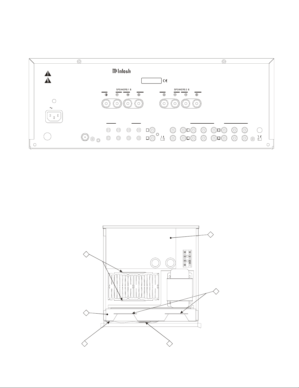
REAR PANEL
RIGHT RIGHTLEFT LEFT
M A 650 0 I N T E G R AT E D A M P LIF IE R
McINTOSH LABORATORY, INC., BINGHAMTON, NEW YORK MADE IN USA
SERIAL
NUMBER
T 10AL 250V
SLO BLO
EXT SENSOR
HEATSINK
PCB
POWER
CONTROL
DATA PORTS IN PU TS
VIDEO
TUNER
CD 2
SUM
HOME
TAPE
POWER
AMP IN
CD 1
LLL
AUX
RRR
EXTPHINT
POWER
AMP INPUT
MAIN
OUT
TAP E
OUT
SECTION LOCATIONS
3
TAPE VIDEO CD 2 CD 1 GNDPH AUX
TUNER
IN P UT /D R IV E R
2
PCB
/
AUX
LAM P
4
PCB
TON E
7
PCB
6 5
CONTROL
PCB
PG D ISPLAY
PC
4
Page 5
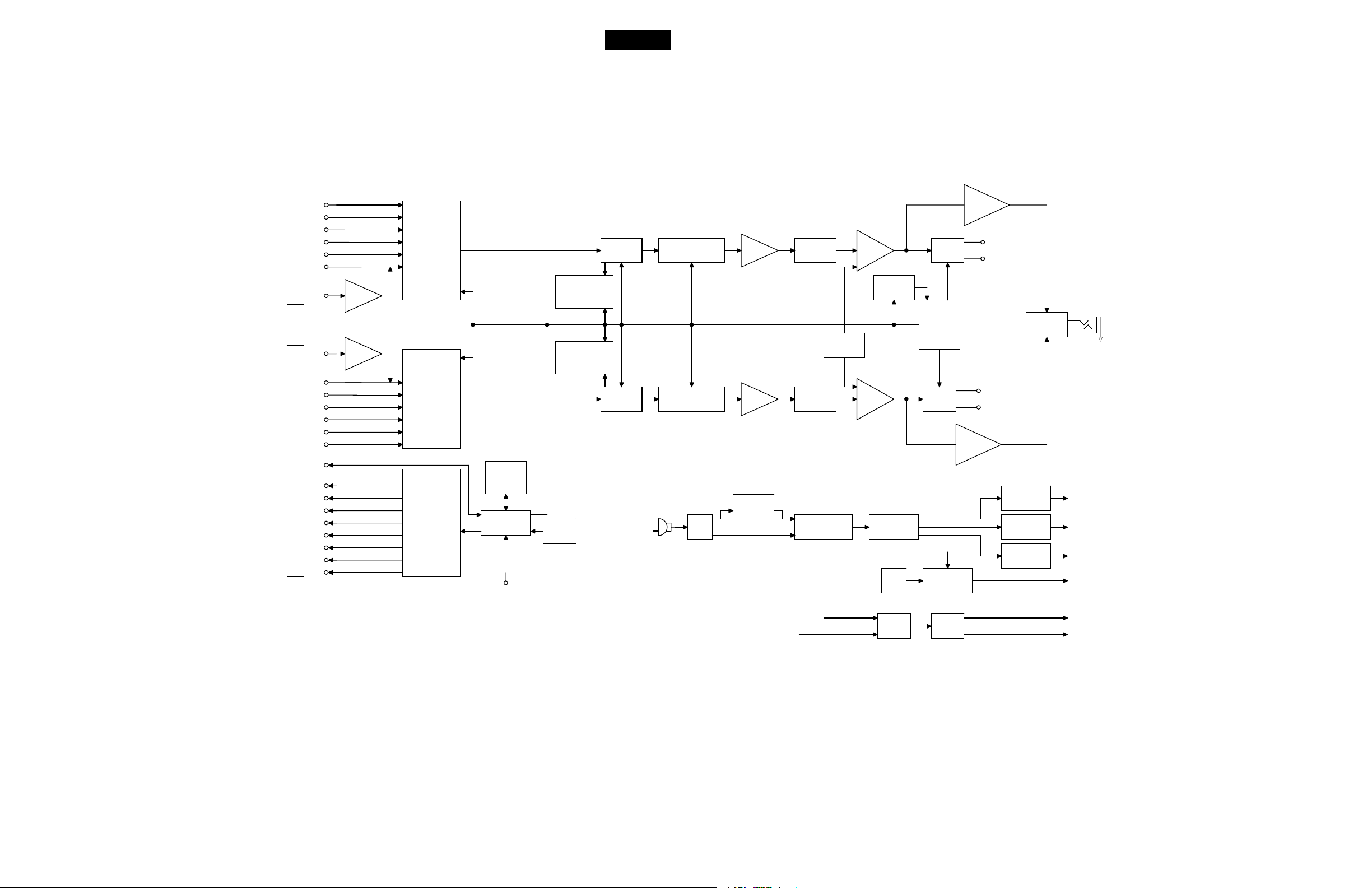
BLOCK DIAGRAM
MA6500
CHANNEL
INPUTS
RIGHT
CHANNEL
INPUTS
PORTS
LEFT
DATA
CD1
CD2
TUNER
VIDEO
TAPE
AUX
PHONO
PHONO
AUX
TAPE
VIDEO
TUNER
CD2
CD1
POWER
CONTROL
AUX
TAPE
VIDEO
TUNER
CD2
CD1
SUM
HOME
R IAA
AMP
R IAA
AMP
INPUT
ELECTRO-
MAGNETIC
SWITCHING
INPUT
INPUT
ELECTRO-
ELECTRO-
MAGNETIC
MAGNETIC
SWITCHING
SWITCHING
DATA
PORT
REGISTER
INPUT
SELECTOR
LOGIC
MICRO
CONTROLLER
EXT IR
SENSOR
COMPENSATION
COMPENSATION
IR
SENSOR
LOUDNESS
CONTROL
LOUDNESS
CONTROL
MONO
SWITCHING
MONO
SWITCHING
120VAC
50/60Hz
SUPER TRACKING
VOLUME CONTROL
SUPER TRACKING
VOLUME CONTROL
MAIN
FUSE
20dB
AMP
20dB
AMP
IN RUSH
CURRENT
LIMITER
BALANCE
CONTROL
CONTROLS
BALANCE
CONTROL
POWER
TRANSFORMER
TONE
TONE
AMP
TONE
AMP
RECTIFIERS
AND FILTERS
LAMP CONTROL
TURN-ON
DELAY
LOGIC
LAMP
FUSE
OUTPUT
MUTING
OUTPUT
MUTING
LOGIC
OUTPUT
MUTING
FRONT PANEL
LAMPS
HEAD-
PHONE
AMP
TO PREAMP IN (INT)
PREAMP OUT RIGHT
HEAD-
PHONE
AMP
TO PREAMP IN (INT)
PREAMP OUT LEFT
5.6V
REGULATOR
15V
REGULATOR
-15V
REGULATOR
MATCHING
NETWORK
5.6V
15V
-15V
11.5VAC
HEAD
PHONE
THERMAL
PROTECTION
MAIN
RELAYS
5
MAIN
SUPPLY
6
B+
B-
Page 6
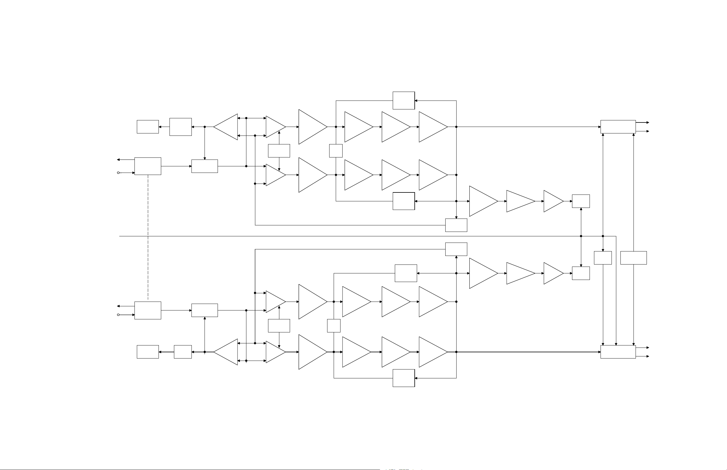
BLOCK DIAGRAM
LEFT PG
INDICATOR
PG
INDICATOR
DRIVER
POWER
GUARD
DIFF
AMP
CASCODE
VOLTAGE
AMP
POSITIVE
CURRENT
LIMITER
+++
PREDRIVER
DRIVER OUTPUT
SPEAKER
SWITCHING
LEFT
OUTPUT
SPEAKER 1
SPEAKER 2
PRE AMP LEFT
(INT)
PRE AMP RIGHT
(INT)
TO PRE AMP
OUT (INT)
PRE AMP IN
(EXT)
PRE AMP IN
(EXT)
TO PRE AMP
OUT (INT)
POWER AMP
INPUT
SWITCH
POWER AMP
INPUT
SWITCH
RIGHT PG
INDICATOR
TO MICRO CONTROLLOR
PG
DRIVER
ELECTRONIC
ATTENUATOR
ELECTRONIC
ATTENUATOR
POWER
GUARD
CURRENT
SOURCE
DIFF
AMP
DIFF
AMP
CURRENT
SOURCE
DIFF
AMP
CASCODE
VOLTAGE
AMP
CASCODE
VOLTAGE
AMP
CASCODE
VOLTAGE
AMP
DC
BIAS
---
PREDRIVER DRIVER OUTPUT
NEGATIVE
CURRENT
LIMITER
NEGATIVE
CURRENT
LIMITER
---
PREDRIVER DRIVER OUTPUT
DC
BIAS
+++
VOLTAGE
LOG
AMP
NEGATIVE
FEEDBACK
NEGATIVE
FEEDBACK
VOLTAGE
LOG
AMP
OUTPUT DRIVER PREDRIVER
RECTIFIER
RECTIFIER
DC
AMP
DC
AMP
LEFT
METER
RIGHT
METER
TURN ON
DELAY
SPEAKER
SWITCHING
THERMAL
PROTECTION
RIGHT
OUTPUT
SPEAKER 1
SPEAKER 2
POSITIVE
CURRENT
LIMITER
7
8
Page 7

INTERCONNECT
MA6500
9
100
Page 8

2
INPUT DRIVER
049193 SH 1 OF 3
11
12
Page 9

MA6500
2
INPUT DRIVER
049193 SH 2 OF 3
13
14
Page 10

2
INPUT DRIVER
049193 SH 3 OF 3
15
16
Page 11

MA6500
2
INPUT DRIVER
17
18
Page 12

3A 3B
HEATSINK
049194
4B4A
LAMP
049235
19
20
Page 13

MA6500
5
PG DISPLAY
049236
6
CONTROL
049195
21
22
Page 14

TONE
7
049268
23
240
Page 15

MA6500
TONE
7
049268
PARTS LIST
PART NO DESCRIPTION REFERENCE NO
049193 INPUT DRIVER
003611 CARD MOUNTING BRACKET SP1 SP2
061196 DISC CAP 47PF,20%,N470 50V C146 C152 C157 C159
061199 DISC CAP 100PF 10% N1500 50V C58 C61 C72 C73 C74
C75 C76 C78 C140 C141
C156 C158
061248 DISC CAP .1MF,25V,Y5T C32 C33 C55
061268 MONO CAP .1UF,50V,Z5U C62 C63 C64 C65 C66
C67 C68 C69 C70 C71
C161 C162 C171 C172
061273 220PF 5% 100V NPO C173 C174 C175
064254 M POLY FILM CAP .1MF,10%,100V C129
064267 M. POLYESTER CAP .22MF,400V C145
064312 CAP M POLY .01UF 5% 63VDC C165 C167
064318 CAP M POLY .033UF 5% 63/100VDC C166 C168
064364 CAP POLYPROP .047MF 10% 250V C47 C144
066269 CAP ELECT 1UF 10% 50V C115 C116
066309 CAP ELECT 1000UF 10V C132
066330 CAP ELECT 220UF 16V SHORT CAN C163 C164
066344 CAP ELECT 100UF 25V C133 C134
066360 CAP ELECT 3300UF 35V C125 C127 C128
066361 CAP ELECT 1000UF 20% 35V C126
066445 ELECT CAP 10MF, 50V AMMO PACK C30 C85 C86 C87 C88
C89 C90 C91 C93 C94
C95 C96 C97 C98 C99
C100 C102 C103 C104
C105 C106 C115 C117
C118 C123 C124 C153
C154 C177
066446 ELECT CAP 47MF, 35V AMMO PACK C92 C101
066447 ELECT CAP 100MF 16V AMMO PACK C22 C40 C119 C120
C121
066462 ELECT CAP 1O UF 100VDC AMMO C35 C36 C37 C38
066469 ELECT CAPACITOR 470MF 50V T&R C176
066504 CAPACITOR ELECT 25000UF 75V C142 C143
070047 SILICON DIODE 1N4148 T&R D1 D3 D4 D5 D6 D7 D8
D9 D10 D21 D22 D25
D26 D27
070130 ZENER DIODE 8.2V,1/2W D2
070131 DIODE RECTIFIER D11 D12 D13 D14 D15
D16 D23 D24
070139 RECTIFIER BRIDGE MC1000 D28
087050 REED RELAY FORM 1A,5V,500 OHMS K2 K3 K4 K5 K6 K7 K8
K9 K10 K11 K12 K13
K16 K17 K18 K20
087057 RELAY K1 K21
087069 POWER RELAY TV5 24V K24
087072 RELAY 24V TV8/VDE CERTIFIED K22 K23
089089 FUSE 2A SLO-BLO 5X20 F1
117215 4-PIN CONNECTOR J3 J8
117219 MALE CONN 10 POS J1
117244 FRICTION LK CONN 9POS MALE J6 J7
117279 11-POS. MALE CONN. J2
117404 HEADER 2-PIN 0.156 J4 J5
117436 PJ261G PHON JACK, GOLD J23
117455 PHONO JACK 8P, GOLD PLATED J21 J22
117494 MINI JACK J28
117549 HEADPHONE JACK DUAL BLACK 1/8 J24 J25 J26 J27
117708 FASTON BLADE W/FEET J10 J11 J12 J13 J14 J15
J16 J17 J18 J19 J2
117712 FASTON BLADE .110 J20
117717 MTA-156 HEADER 8PIN J9
122297 CHOKE OUTPUT .65UH L2 L3
132172 TRANSISTOR SI PNP MPSA55 Q50
132193 TRANSISTOR J.F.E.T. 2N4392 Q62 Q64
132223 TRANSISTOR NPN MPS4124 2K/REEL Q44 Q46 Q47Q57 Q58
Q59 Q61Q63 Q66 Q75
Q78 Q79 Q80 Q81 Q83
Q87 Q88
132224 TRANSISTOR PNP Q1 Q40 Q48 Q49 Q52
Q69 Q73 Q74 Q76 Q77
132254 TRANSISTOR NPN Q54 Q55 Q56 Q67 Q68
Q71 Q85 Q86
132255 TRANSISTOR PNP Q2 Q51 Q53 Q65 Q70
Q72
132261 TRANSISTOR PNP Q18 Q82
132262 TRANSISTOR NPN Q17 Q84
133028 IC OPERATIONAL AMPLIFIER IC1 IC3
133067 NE5534AN OP AMP LOW NOISE IC16 IC17
133108 IC +5V REGULATOR IC5
133153 IC REGULATOR -15V IC6
133154 IC REGULATOR 15V IC7
133175 IC AND 2 INPUT X 4 IC14
133180 LB1720 8 LN DRIVER ARRAY IC10 IC13
133186 IC SHFT REG SER-PAR IC9 IC11 IC12
133260 DUAL OPERATIONAL AMPLIFIER IC2 IC4 IC15
133360 OCTAL DAR TRANS ARRAY W/DIODE IC8
134389 TRIM POT 100K,10%,3/8SQ. R237 R238
137042 FLAMEPROOF RES 47 OHM 5% 1/4W R56 R60
141165 RES CF 10 5% 1/2W R77 R79 R119 R230
R231 R232
144053 RES MF 10K 1% 1/4W R122 R134 R171 R217
R218
144071 METAL FILM RES 365 OHM 1% 1/4W R265 R266 R267 R268
R269 R270 R271 R272
144086 METAL FILM RES 475 OHM 1% 1/4W R45 R167 R168 R187
144090 METAL FILM RES 1K 1% 1/4W R36 R164 R170 R184
R241 R242 R249 R255
R262 R263 R264
144095 RES MF 3.32K 1% 1/4W R41 R55 R188 R193
25
26
Page 16

PARTS LIST
con’t
144097 METAL FILM RES 4.75K 1% 1/4W R46 R86 R177 R222
R227 R233 R234
144107 METAL FILM RES 40.2K 1% 1/4W R161 R192
144108 RES MF 47.5K 1% 1/4W R29 R62 R65 R66 R69
R175 R181 R182 R247
R251
144113 RES MF 100K 1% 1/4W R100 R162 R196 R228
144119 METAL FILM RES 332K 1% 1/4W R221 R226
144125 METAL FILM RES 150K 2% 1/4W R169 R190
144127 METAL FILM RES 95.3K 1% 1/4W R248 R257
144141 METAL FILM RES 27.4K 1% 1/4W R219 R223
144154 RES MF 12.1K 1% 1/4W R128 R172
144160 METAL FILM RES 22.1OHM 1% 1/4W R152 R156
144172 RES MF 221 OHMS 1% 1/4W R51 R53 R145 R146
R160 R186 R239 R240
144187 METAL FILM RES 22.1K 1% 1/4W R104 R105
144191 RESISTOR MF 1.21K 1% 1/4W R38 R101 R159 R173
144196 METAL FILM RES 100 OHM 1% 1/4W R67 R68 R136 R137
R138 R139 R140 R141
R142 R144 R150
144210 RES MF 7.5K 1% 1/4W CRB1/4FX R245 R253
144220 95.3 OHMS 1% 1/4W MF R246 R256
144225 MF RES, 30K OHM 1% 1/4W R147 R148 R258 R259
144262 RES NETWORK, 2X220K, ISO R1 R2 R3 R4 R5 R6 R7
R154 R243
144264 METAL FILM RES 10M 1% 1/4W R220 R224
144265 METAL FILM RES 2.21M 1/4W R225 R229
144273 RESISTOR MF 182 OHM 1/4W 1% R157 R205
144338 RES MF 324 OHM 1% 1/4W R163 R194
144378 RES MF 2.21 OHM 1/4W 1% R250 R252
144440 MF RES 14.3K 1% 1/4W R50 R165
144441 METAL FILM RES 274K 1% 1/4W R52 R158 R176
R178 R179 R195
144442 METAL FILM RES 47.5 1% 1/4W R244 R254
144443 METAL FILM RES 681K 1% 1/4W R30 R37 R83 R166 R174
148059 SLIDE SWITCH S1 S2
178159 FUSE HOLDER 5X20MM PCB MOUNT F1
049194 HEATSINK
061023 DISC CAP 100PF 10% N1500 C7 C8
061159 CERAMIC CAP .01MF +80-20% 50V C9 C16
061248 DISC CAP .1MF,25V,Y5T C3 C5
064363 CAP POLYPROP 0.15MF 10% 250VDC C10
066446 ELECT CAP 47MF, 35V AMMO PACK C1 C2
070047 SILICON DIODE 1N4148 T&R D1 D2 D3 D4 D5
070133 DIODE 200V,6A D6 D7
117213 2-PIN MALE CONNECTOR J3
117244 FRICTION LK CONN 9POS MALE J1
117404 HEADER 2-PIN 0.156 J2
132223 TRANSISTOR NPN MPS4124 2K/REEL Q1
132224 TRANSISTOR PNP Q2
132261 TRANSISTOR PNP Q7
132262 TRANSISTOR NPN Q6
134390 TRIM POT 200 OHM 20% HORIZ AD R13
137093 MET OX 680 5% .5W R2 R9
137094 MET OX 1.8K 5% .5W R6 R11
137095 MET OX 430 5% .5W R7
137096 MET OX 47 5% .5W R12
139177 WIREWOUND RES 0.5 OHM 5W 5% R31 R32 R33 R34 R35
R36 R37 R38
144053 RES MF 10K 1% 1/4W R3 R10
144172 RES MF 221 OHMS 1% 1/4W R1 R8
144279 THERMISTOR 100 OHM RT1
144378 RES MF 2.21 OHM 1/4W 1% R30
049195 CONTROL
058153 INCANDESCENT LAMP 14V 100MA DS13 DS14 DS15DS16
DS17 DS18
061268 MONO CAP .1UF,50V,Z5U C3 C5 C6 C7 C10
061273 220PF 5% 100V NPO C8 C9
061277 MONO CAP 0.1MF 20% 50V C1
066254 CAP ELECT 220UF 50V 20% C2
066330 CAP ELECT 220UF 16V SHORT CAN C4
070093 LED LAMP RED DS1 DS2 DS3 DS4 DS5
DS6 DS7 DS8 DS9 DS10
DS11 DS12
117216 MALE CONN 5-PIN 0.1 POST ASSY J4
117279 11-POS. MALE CONN. J1
117462 PHON JACK 1 1/8” STEREO VER J3
121031 IR SENSOR 38KHZ MT1
133175 IC AND 2 INPUT X 4 IC1
133186 IC SHFT REG SER-PAR IC3 IC4
133191 IC DC MOTOR DRIVER IC2
133241 IC MICROPRCSSR RESET POS IC6
133394 PROGRAMMED DEVICE
144053 RES MF 10K 1% 1/4W R5 R16
144090 METAL FILM RES 1K 1% 1/4W R14 R15
144113 RES MF 100K 1% 1/4W R2
144157 METAL FILM RES:10 OHMS 1% 1/4W R4
144196 METAL FILM RES 100 OHM 1% 1/4W R1
144290 RES NETWORK 3 X 10K BUSSED R6
144338 RES MF 324 OHM 1% 1/4W R7 R8 R9 R10 R11 R12
R13
144378 RES MF 2.21 OHM 1/4W 1% R19
144444 METAL FILM RES 75 1% 1/4W R 3
150058 TACT SWITCH S1 S2 S3 S4 S5 S6 S7 S8
S9 S10 S11S12
178139 IC SOCKET 24-PIN IC5
180039 CERAM RESON 6.0MHZ W/CAP Y1
049235 LAMP
058120 LAMP 14V #7373 DS1 DS2 DS3
117240 4 PIN RT. ANGLE J1
117274 CONN. 2 POS. R-ANGLE J2
049236 POWER GUARD
058133 AMBER LED DS1 DS2
058153 INCANDESCENT LAMP 14V 100MA DS3 DS4
117215 4-PIN CONNECTOR J2 J3 J4
117216 MALE CONN 5-PIN 0.1 POST ASSY J1
049268 TONE
061191 DISC CAP 22PF,10%,NPO 50V C3 C4
061196 DISC CAP 47PF,20%,N470 50V C16 C17
061256 M.CAP 470PF,5%,100V C26 C27 C38 C39
061260 MONOLYTHIC, 220PF C1 C2
061268 MONO CAP .1UF,50V,Z5U C28 C30 C31 C33 C36
C37
064254 M POLY FILM CAP .1MF,10%,100V C5 C6
064318 CAP M POLY .033UF 5% 63/100VDC C18 C19 C20 C21
064329 CAP M POLY .22UF 5% 63VDC C40 C41 C42 C43
066330 CAP ELECT 220UF 16V SHORT CAN C44 C45
066345 CAP ELECT 22UF 50V C9 C12
066378 CAP ELECT 47UF 16V BP C15
066445 ELECT CAP 10MF, 50V AMMO PACK C7 C10 C11 C14 C34
C35
066446 ELECT CAP 47MF, 35V AMMO PACK C22 C2324 C25
070047 SILICON DIODE 1N4148 T&R D1 D2
087050 REED RELAY FORM 1A,5V,500 OHMS K1 K2 K3
117219 MALE CONN 10 POS J1
117707 CONNECTOR MALE 6 POS RT ANGLE J2
133260 DUAL OPERATIONAL AMPLIFIER IC1 IC2 IC3 IC4
134457 POT, EQUAL R33 R34
134464 POTENTIOMETER BALANCE 2KOHM R32
134490 POTENTIOMETER 50KAX2 R1
144015 METAL FILM RES 33.2K 1% 1/4W R23 R25
144053 RES MF 10K 1% 1/4W R9 R27
144086 METAL FILM RES 475 OHM 1% 1/4W R14 R28
144090 METAL FILM RES 1K 1% 1/4W R6 R11 R13 R17
144095 RES MF 3.32K 1% 1/4W R21 R22
144107 METAL FILM RES 40.2K 1% 1/4W R39 R40
144113 RES MF 100K 1% 1/4W R12 R15 R16 R29 R36
R38
144157 METAL FILM RES 10 OHMS 1% 1/4W R8 R10
144160 METAL FILM RES 22.1OH 1% 1/4W R2 R26
144195 MF RES, 681 OHM 1% 1/4W R5 R20
144196 METAL FILM RES 100 OHM 1% 1/4W R35 R37
144298 MF 2.21K 1% 1/4W R30 R31
144304 MF 2.74K 1% 1/4W R3 R18 R19 R24
144364 RES MF 475K 1% 1/4W R4 R7
27
280
Page 17

EXPLODED VIEW
MA6500
29
30
Page 18

EXPLODED VIEW PARTS LIST NOTES
Ref. Part Description
No. No.
1 016404 FRONT PANEL GLASS
2 004899 EXTRUSION BRACKET
3 018612 END CAP
4 101042 TS 4-40 X 1/2 SLOT FILLISTER
5 171260 C/A INPUT/POWER SWITCH
6 017531 PUSHBUTTON ASSY RED
7 017517 PUSHBUTTON ASSY
8 017736 HEADPHONE BEZEL
9 078033 O-RING
10 090258 KNOB 25mm INDEX
11 104073 FELT W MPI-4 1/4 X 5/8
12 018605 BOTTOM EXTRUSION
13 101172 TCS 6-32 X 1/4 PHIL FLAT U/C
14 101054 TS 6-32 X 1/4 PHIL PAN TAPTITE
15 018587 TOP EXTRUSION
16 094350 SENSOR GASKET
17 017764 DISPLAY PLEXIGLAS
18 022314 FISHPAPER SHEILD
19 017363 PLEXIGLAS FILTER LIGHT BLUE
20 004966 SUBPANEL
21 049195 CONTROL PCB ASSY
22 129284 TONE PCB ASSY
23 100275 MS 6-32 X 1/2 PHIL BLK TRUSS HD
24 021030 SPACER 6 X 1/4
25 078031 GROMMET
26 049236 POWER GUARD DISPLAY ASSY
27 021094 SPACER 4 X 1/4
28 102001 KEP NUT 4-40 CADMIUM PLATE
29 124074 MC202 METER
30 092341 FILTER AZURE BLUE
31 092342 FILTER PALE BLUE
32 017447 PLASTIC LIGHT BOX
33 049235 LAMP PCB ASSY
34 114072 PLASTIC RIVET
35 159310 POWER TRANSFORMER
36 102007 MACH NUT 1/4-20 W/LOCK
37 004964 TRAY
38 102003 MACH NUT 6-32 W/LOCK
39 004965 CHASSIS
40 017218 PLASTIC FEET - BLACK
41 104080 FLAT WASHER #10 CLEAR ZINC
42 100159 MS 10-32 X 3/4 PHIL PAN ZINC
43 101176 TCS 6-32 X 1/2 PH PAN BLK TYPE F
44 074091 AC TERMINAL BLOCK
45 104001 FLAT STEEL WASHER #4 X 9/32 X .025
46 104004 LK WASHER 5 X .255 INT STAR
47 102022 MN 4-40 3/16 X 1/16
48 112038 STL SPACER 4 X 3/8 L NICKEL PLT
49 021038 SPACER #6 X 3/8
50 084135 THERMAL PAD MC7150
51 106007 SPRING CLIP LATCH TYPE
52 049194 HEATSINK PCB ASSY
53 101059 SM 6 X 5/8 PHIL PAN TYPE A
54 114119 TRANSISTOR CLIP 214
55 114118 TRANSISTOR CLIP 218
56 112087 PCB SPACER 1/4”
57 084194 ISOSTRATE
58 018616 AMPLIFIER HEATSINK 4 INCH
59 017160 MOUNTING TAB W/.140 DIA MTG
60 049193 INPUT/DRIVER PCB ASSY
61 102014 MACH NUT 6-32 W/LOCK
62 110009 NUT M5 X 0.8 BRASS W/GOLD PLATE
63 104130 LW #10 SPLIT PHOS/BRONZE
64 104148 FLAT WASHER BRASS
65 004800 OUTPUT PLATE
66 100250 SEMS 6-32 X 1/4 PHIL PAN
67 102020 MACH NUT 6-32 SELF-LOCK
68 104016 LK WASHER 1/2 X .630 X .022 INT STAR
69 178122 SOCKET FUSEHOLDER UL/CSA
70 117487 MC1000 AC LINE RECEPTACLE
71 117369 COAX RECEPTACLE GOLD TYPE F
72 101197 HI/LO 4-32 X 3/8 PH ROUND BLACK
73 084124 DUAL BINDING POST
74 084112 GROUND POST (GOLD) 4300
75 004962 REAR PANEL
76 101109 TS 6-32 X 5/16 PHIL PAN
77 004798 TOP COVER
78 101078 TS 8-32 X 5/16 PHIL PAN
79 017706 TERMINAL COVER
80 100072 LOCK WASHER 1/4 X .396 INT STAR
81 100126 MS 1/4-20 X 5/8 PHIL PAN BLACK
82 094017 FOAM TAPE 1/4 X 1/4
31
32
Page 19

REPACKING INSTRUCTIONS
33
Page 20

INTEGRATED AMPLIFIER
SERVICE MANUAL
The continuous improvement of it’s products is the policy of McIntosh Laboratory Incorporated, who reserve the right to improve design with out notice.
Because of the constant upgrading of McIntosh products’ circuitry and components, the Company cannot insure, and does not warrant, the accuracy of the
within schematic material, which is intended for information only.
McINTOSH LABORATORY, INC., 2 CHAMBERS STREET, BINGHAMTON, NEW YORK 13903 Printed in U.S.A. Part Number 040703
 Loading...