

Page 1
McIntosh Laboratory, Inc. 2 Chambers Street Binghamton, New York 13903-2699 Phone: 607-723-3512 www.mcintoshlabs.com
C8
Tube Preamplier
Ow ner’s M a nu a l
Page 2
The C8 Tube Preamplifier marries McIntosh’s long
tradition of uncompromising quality and leadership in
Vacuum Tube amplification with the latest cutting edge
innovations to bring you an unsurpassed luxury sonic
experience.
Thank you from all of us at
McIntosh
With the C8 Tube Preamplier, you have invested in a
precision instrument that will provide you with many
years of enjoyment. Please take a few moments to
familiarize yourself with the features and instructions
to get the maximum performance from your equipment.
If you need further technical assistance, please contact
your dealer who may be more familiar with your
particular setup including other brands. You can also
contact McIntosh with additional questions or in the
unlikely event of needing service.
McIntosh Laboratory, Inc.
2 Chambers Street
Binghamton, New York 13903
Technical Assistance: (607) 723-3512
Customer Service: (607) 723-3515
Fax: (607) 724-0549
Email: support@mcintoshlabs.com
Website: mcintoshlabs.com
Make a Note
For future reference, you can jot down your serial
number and purchase information here. We can
identify your purchase from this information if the
occasion should arise.
Serial Number:
Purchase Date:
Dealer Name
Safety First
Important Safety Information is
supplied in a separate document
“Important Additional Operation
Information Guide”
Copyright 2020 © by McIntosh Laboratory, Inc
2
Page 3

Table of Contents
Thank you from all of us at McIntosh ........................ 2
Make a Note ................................................................ 2
Safety First .................................................................. 2
Remove the Foam ....................................................... 4
Where to put it ............................................................ 6
The Front Panel ........................................................... 7
The Left Knob ..................................................7
The Right Knob ................................................ 7
Connections on the Back ............................................ 8
The Inputs ......................................................... 8
The Outputs ...................................................... 8
Making Connections ................................................... 8
Phono/Unbalanced Inputs ................................. 8
Balanced/XLR Input and Output ..................... 9
RS232 ................................................................ 9
Wired IR Input .................................................. 9
Connection Diagram ....................................... 10
DA2 Expansion Slot ........................................ 11
Power Control (Trigger) Outputs .................... 11
Data Out .......................................................... 11
Power On the C8 ....................................................... 12
Trim Functions and Settings ..................................... 12
Phono Trim Function ...................................... 12
Setup Settings ........................................................... 13
Firmware and Serial Number ......................... 13
Input Setup ...................................................... 13
Output 2 (SUB) ............................................... 13
Trigger Setup ................................................. 13
Data Port Setup ............................................... 14
Passthru........................................................... 14
RS232 Setup.................................................... 14
IR Codes Setup ............................................... 14
Front IR Setup ................................................. 14
Auto-Off Setup ............................................... 15
FACTORY RESET ......................................... 15
Remote Control Buttons ........................................... 16
Changing the Remote’s Battery ............................... 17
Packing the C8 .......................................................... 18
Specifications ........................................................... 19
IMPORTANT!
INSTRUCTIONS FOR REMOVAL OF
FOAM INSERT OVER THE VACUUM
TUBES PRIOR TO CONNECTING THE
A.C. POWER SUPPLY CORD, START
ON THE NEXT PAGE.
List of Figures
Figure 01– C8 Dimensions ................................. 6
Figure 02– Ventilation requirements .................. 6
Figure 03– Front Panel ....................................... 7
Figure 04– C8 Rear View ................................... 8
Figure 05– RCA/Phono Plugs ............................. 9
Figure 06– XLR pin diagram ............................. 9
Figure 07– Mini plug for RS232 connection ...... 9
Figure 08– DB9 connector pin layout ................ 9
Figure 09– IR 3.5mm connector ......................... 9
Figure 10– Power control (trigger) mini plug ....11
Figure 11– 3.5mm Data plug ..............................12
Figure 12– Inputs Menu .....................................13
Figure 13– Opening the Remote Control ..........17
Figure 14– Re-packing diagram ........................18
3
Page 4
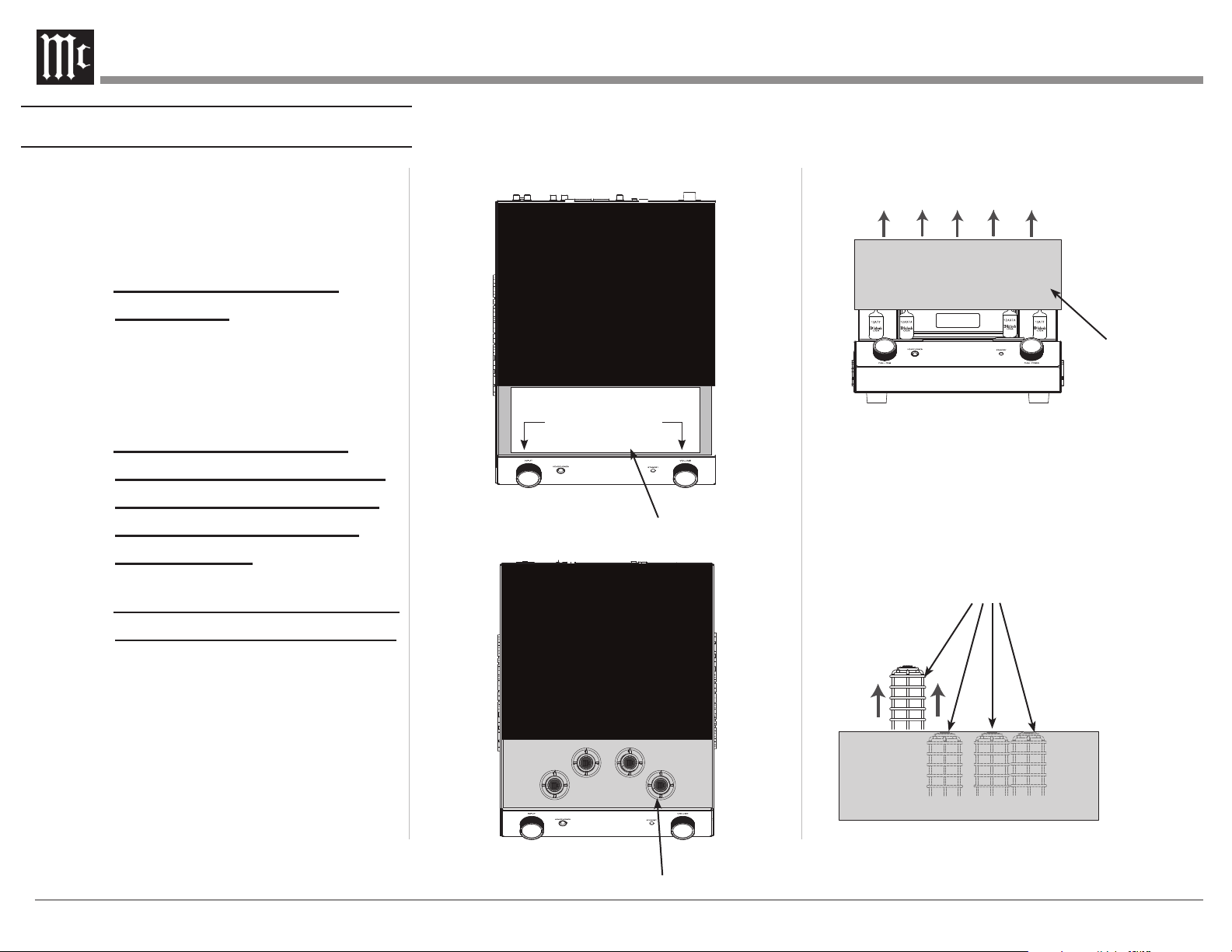
Remove the Foam
Caution: To prevent damage to the C8 Tubes
during shipping, there is a special
foam insert surrounding the Tubes
of the Preamplifier.
The Foam Insert must
2. Remove the Warning Sheet and save it with the
Shipping Carton for possible future use. Refer to
Figures A and B.
3. Carefully lift upright the Foam Insert Vacuum
Tube Cover and place it near to the C8
Preamplifier. Refer to Figure C.
be removed from the C8
before connecting the AC
Power Supply Cord to the
Preamplif ier.
Failure to do so has the
potential of a Fire Hazard,
resulting in damage to the
C8 and the surrounding
environment.
Follow these instructions for
removal of the packing foam
before connecting the AC
Power Supply Cord to the
C8.
The C8 has no user serviceable parts, including the
tubes. If repairs are needed they must be performed by
an authorized McIntosh Service Agency. Follow the
steps below to prepare the C8 for operation:
1. Orient the C8 so the Front and Top of the
Preamplifier is facing you. Refer to Figure A.
WARNING
TO AVOID A FIRE HAZARD, THE FOAM INSERT
OVER THE VACUUM TUBES MUST BE REMOVED
PRIOR TO CONNECTING THE AC POWER CORD
AND OPERATING THIS PRODUCT.
REFER TO THE OWNER’S
MANUAL FOR INSTRUCTIONS.
Figure A
Remove the Warning Sheet
Figure B
Vacuum Tube Shield Covers
Remove the
Foam Insert
Vacuum
Tube Cover
Figure C
4. Remove from the Foam, the four Vacuum Tube
Shield Covers and place them along the side of the
C8 Preamplifier. Save the Foam Insert Vacuum
Tube Cover with the Shipping Carton for possible
future use. Refer to Figure D.
Remove the four Vacuum Tube Shield Covers
Figure D
4
Page 5
WA R N I NG:
7-
17.9cm
VOLUME
INPUT
HHEEAADDPPHHOONNEESS
PPUUSSHH -- TTRRIIMM PPUUSSHH -- PPOOWWEERR
CC 88 TTUU BBEE PPRR EE AAMMPPLLIIFFIIEE RR
The supplied Vacuum Tube Shield
Covers must be installed over
each of the four Small Vacuum
Tubes before the C8 Preamplifier
is connected to AC Power and
activated for use!!
Failure to do so has the potential
to cause physical harm to human
beings and animals.
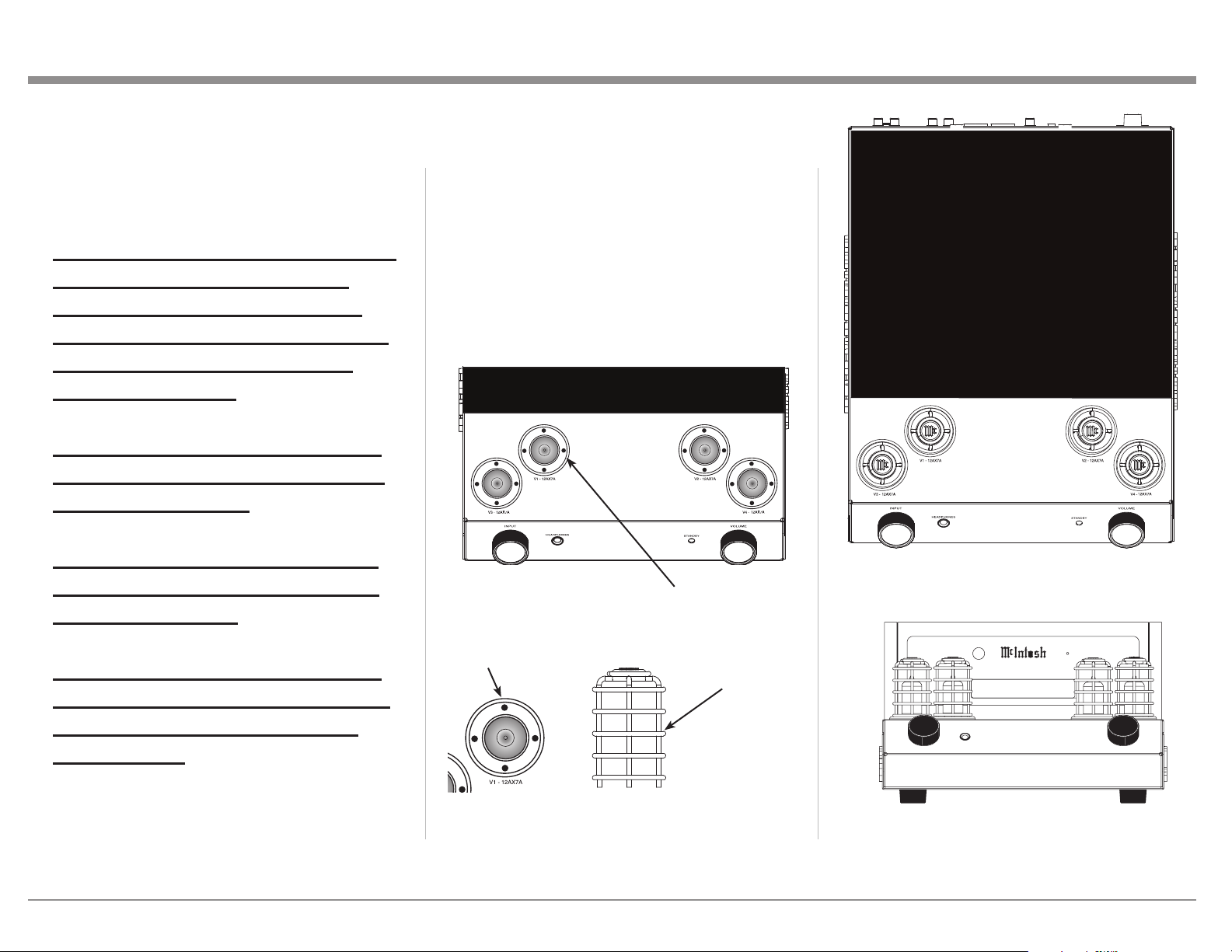
5. The C8 Preamplifier has four Small Vacuum
Tubes that are inserted into special Vacuum Tube
Sockets on the Stainless Steel Chassis. Refer to
Figure E.
Each of the Tube Sockets have four pin openings
to accept the Vacuum Tube Shield Covers. Refer
to Figure F.
Carefully install the Vacuum Tube Shield Covers
into each of the Vacuum Tube Sockets orienting
the Shield so the “Mc” on top of the Shield is
facing forward. Refer to Figures G and H.
This could also result in damage
to the Vacuum Tubes and the C8
Internal Circuitry.
It also prevents the potential of a
Fire Hazard, resulting in damage
to the C8 and the surrounding
environment.
Figure E
Pin Openings
Figure G
Special Vacuum Tube Sockets
Vacuum Tube
Shield Covers
Figure F
Figure H
5
Page 6
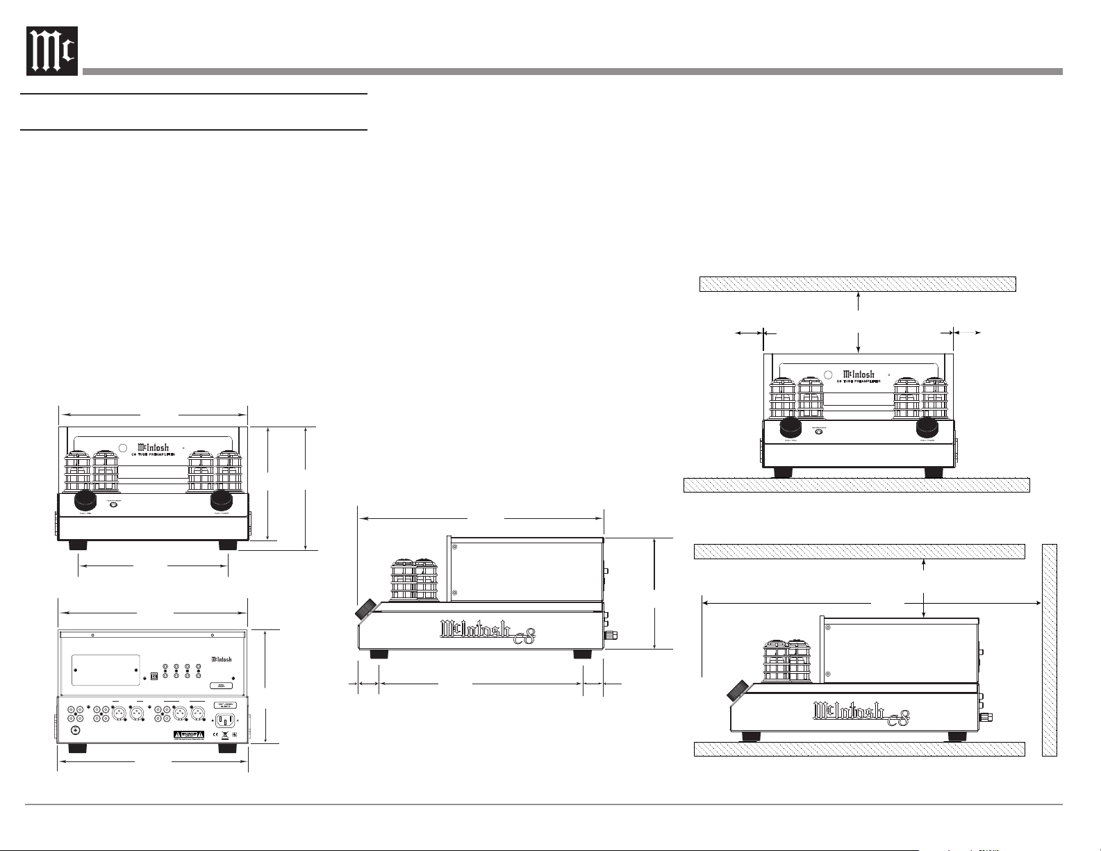
Where to put it
The C8 can be placed upright on a table or shelf,
standing on its four feet. It also can be custom
installed in a piece of furniture or cabinet.
Always provide adequate ventilation for your C8.
Cool operation ensures the longest possible operating
life for any electronic instrument. Do not install the
C8 directly above a heat generating component such
as a high-powered amplier. If all the components
are installed in a single cabinet, a quiet running
ventilation fan can be a denite asset in maintaining
all the system components at the coolest possible
operating temperature.
A custom cabinet installation should provide the
following minimum spacing dimensions for cool
operation (see Figure 02):
• 6 inches (15.3cm) above the top
• 5/8 inches (1.6cm) below the bottom
• 2 inches (5.1cm) on each side of the C8 so that
airow is not obstructed
• 18 inches (45.7cm) depth behind the front panel
• 1-7/16 inch (3.7cm) in front of the mounting
panel for knob clearance
6"
2"
5.1cm
15.3cm
C8 TU BE P RE AM PL IF IE R
2"
5.1cm
11-7/8"
30.2cm
C8 T UB E PR EA MP LI FI ER
INPUT
HEADPHONES
PUSH - TRIM PUSH - POWER
9-3/8"
23.8cm
Rear View of the C8
11-1/2"
29.2cm
EXTERNAL
DATA
POWER CONTROL
CONTROL
PORTS
1 MAIN TRIG 1
RS232
SERVICE
PORT
IR IN
2 PASSTHRU TRIG 2
OUTPUT 2
R
L
PHONO INPUTS
MC MM
UNBALANCED INPUTS
BALANCED INPUT
L
1 2
R
R
L
GND
12 - "
R
L
1/32
30.6cm
(SUB) UNBAL
OUTPUT 1
BAL R BAL L
VOLUME
C8 TUBE PREAMPLIFIER
McINTOSH LABORATORY, INC., BINGHAMTON, NY
HANDCRAFTED IN USA WITH US AND IMPORTED PARTS
7-1/32
17.9cm
7- "
1/32
17.9cm
Front View of the C8
7-5/8"
"
19.4cm
1-5/16"
3.36cm
Figure 01– C8 Dimensions
Side View of the C8
15-3/8"
39.0cm
12-3/4 "
32.4cm
1-5/16"
3.3cm
7-1/32"
17.9cm
INPUT
HEADPHONES
PUSH - TRIM PUSH - POWER
18"
45.7cm
VOLUME
6"
15.3cm
Figure 02– Ventilation requirements
6
Page 7

The Front Panel
The C8’s glass and metal Front Panel provides two
control knobs and an informational display (VFD).
The Le Knob
The Left Knob, labeled INPUT, is used to change
inputs, enter Trim setting mode and to enter Setup
mode.
• Turn clockwise or counterclockwise to scroll
through inputs
• Push and release to enter Trim Mode
• Push, hold and release after 2 seconds to enter
Setup mode
The Right Knob
The Right Knob, labeled VOLUME , is used to
change the volume as well scroll through input
values within Trim Mode. Push and release the knob
to Power Off. Push the Right Knob to Power On
when the C8 is off.
• Turn clockwise or counterclockwise to scroll
through input values in Setup mode or Trim
Mode
• Push and release to Power On when C8 is Off
• Push and release to Power Off.
The Standby Indicator LED will glow red as long as
AC Power is connected to the C8.
Infrared (IR) Sensor
Left Knob
Standby Indicator LED
Right Knob
Vacuum Flourescent Display (VFD)
Headphone Jack
Figure 03– Front Panel
7
Page 8

Figure 04– C8 Rear View
Connecons on the Back
The Inputs
One stereo pair of Moving Coil Phono inputs (A)
One stereo pair of Moving Magnet Phono inputs (B)
Two pair of stereo Unbalanced inputs- RCA Jacks
(C) (D)
One Stereo pair of Balanced inputs (E)
One 1/8-inch jack for RS232 connector (K)
One 1/8-inch jack for wired IR Input (L)
One 1/8-inch PASSTHRU jack (N)
One AC power connector (I)
One USB upgrade service port (Y)
8
One DA2 expansion slot (X)
One Ground Connector (Z)
The Outputs
One Pair unbalanced RCA Output #1 (G)
One pair balanced XLR audio Output #1 (H)
One pair unbalanced RCA SUB/Output #2 (F)
Two 1/8-inch Data Output jack (J)
Three 1/8-inch jack Power Control (trigger) Outputs
(M) (O) (P)
Making Connecons
Phono/Unbalanced Inputs
Unbalanced Inputs such as the two PHONO
INPUTS and UNBALANCED INPUTS 1 and 2
use RCA/phono cables to connect the C8 to other
components. See “Figure 05– RCA/Phono Plugs”
on page 9. Traditionally, the red connector is
used to connect the right channel. You are free to
break tradition but keep the channels straight or left
and right might be reversed.
Page 9

Figure 05– RCA/Phono Plugs
PIN 3
The C8 can accept the analog input from a wide
variety on components such as CD players, tuners,
and turntables. There are two sets of unbalanced
inputs dedicated for turntable connections which
allow customization of the input level. See Phono
Adjustments on page 28.. The signal strength from
phono cartridges vary and are lower than the line
level received from most other components. The
turntable will also have a ground connection which
should be secured to the C8’s GND Binding Post to
eliminate ground hum. Turn the Binding Post
counterclockwise to loosen and attach the ground
wire. Turn the Binding Post clockwise to secure the
ground connection.
The MC PHONO INPUT should be used for low
output Moving Coil Cartridges. The MM PHONO
INPUT should be used for Moving Magnet and high
output Moving Coil Cartridges.
Balanced/XLR Input and Output
The BALANCED INPUT allows a source to be
connected using XLR (balanced) cables if the
source has this option.
XLR cables can also be used to connect the C8 to an
amplier. OUTPUT1 has a pair of XLR connectors
as well as a pair of RCA connectors. Both outputs
can be used simultaneously if desired as in the case
of bi-amping. To use the XLR output, connect the
BAL R to the right input of your amplier and BAL
L to the amplier’s left input.
Below is the Pin conguration for the XLR
Balanced Input and Output Connectors on the C8.
Refer to the diagrams for connections:
PIN 1: Shield/Ground
PIN 2: + Signal
PIN 3: - Signal
PIN 1
Figure 06– XLR pin diagram
PIN 2
RS232
The RS232 jack is used to connect the C8 to
automation controller devices with RS232
connectors. To utilize this feature, you will need an
Data In
(DB9-pin2)
Data Out
(DB9-pin3)
Ground
(DB9-pin5)
Figure 07– Mini plug for RS232 connection
appropriate RS232 Data Cable. The RS232 Data
Cable should be an 1/8 inch (3.5mm) stereo mini
phone plug to a subminiature DB9 connector.
Figure 08– DB9 connector pin layout
RS232 DB9 Connector Pin Layout
1. N/C (no connection) 6. N/C
2. Data In (RXD) 7. N/C
3. Data Out (TXD) 8. N/C
4. N/C 9. N/C
5. Gnd
Typical RS232 settings are:
• 8 data bits, no parity and one stop bit
• Baud rate xed at 115,200 bits per second
The baud rate can be changed in the Setup. See
“RS232 Setup” on page 14.
Wired IR Input
The IR Input allows an external IR receiver to be
attached to the C8. The Input is labeled IR IN. By
attaching an IR receiver using a 3.5mm cable (see
Figure 09), the C8’s Remote Control can be used in
another location without a line-of-sight to the C8’s
front IR sensor.
IR Data
Control
N/C
Ground
If using an external IR receiver for the MAIN
ZONE in the same room as the C8, you may wish
to disable the front IR sensor. This will avoid
potential timing issues of receiving the Remote
Control’s commands from two different Inputs.
The front IR can be turned on/off by doing the
following:
• Press and Hold the Left Knob for two seconds
• Turn the Left Knob to the menu choice
“SETUP: Front IR”
(Continued on page 11)
Figure 09– IR 3.5mm connector
9
Page 10

Connecon Diagram
There are many possible connections for the C8
depending on your system. This diagram shows a
few typical ones.
Connect to a Data
Port In on a source
Connect to a
Power Control
(Trigger) Input
IR Sensor
Connect to Subwoofer
or second amplifier.
Can be set to stereo or
mono
Connect to AC
Outlet
10
Connect a Moving Magnet
Turntable to MM.
Connect a Moving Coil to MC.
Use ground for either
Use Unbalanced or Balanced
connections for sources such as CD
players, tuners, streamers or other
analog sources
McINTOSH LABORATORY, INC., BINGHAMTON, NY
HANDCRAFTED IN USA WITH US AND IMPORTED PARTS
INPUT MODE AUTO OFF PWR CONTROLBALANCED IN
UNBALANCED IN
/
DISENAUNBALBAL
OUTPUT
CLASS 2 WIRING
FUSE
IN
T5AL 250V
PUSH
OUT
120V ~ 50/60Hz
3.7A
UNBALANCED IN
Use Balanced or Unbalanced
connection to connect to a power
amplifier or amplifiers
McINTOSH LABORATORY, INC., BINGHAMTON, NY
HANDCRAFTED IN USA WITH US AND IMPORTED PARTS
INPUT MODE AUTO OFF PWR CONTROLBALANCED IN
/
DISENAUNBALBAL
OUTPUT
CLASS 2 WIRING
FUSE
IN
T5AL 250V
PUSH
OUT
120V ~ 50/60Hz
3.7A
Page 11

• Turn the Right Knob clockwise for Enabled
(on) or counterclockwise (off)
• Press and release the Left Knob to exit the
Setup menu
DA2 Expansion Slot
The C8 has an expansion slot to allow for the
installation of the DA2 Digital Audio Module. The
DA2 will add the following digital audio inputs:
• two coax
• two optical
• one HDMI (ARC)
• one MCT
• one USB audio
Due to the technical nature of the DA2 upgrade,
the upgrade must be performed by a qualied
trained professional at an Authorized McIntosh
Dealer or Authorized McIntosh Service Agency.
Please note that if the upgrade is performed by
anyone other than an Authorized McIntosh Dealer
or Authorized McIntosh Service Agency, under
the terms of your McIntosh Limited Warranty any
resulting damage or failure of your unit will be
excluded from warranty coverage. Contact your
local Authorized McIntosh Dealer or Authorized
McIntosh Service Agency to schedule your upgrade
if you wish to add digital capabilities to your C8.
AC Power
This connection is essential. Plug the female end of
the supplied AC Power Cord into the AC connector
(standard 15 ampere IEC) located in the rear right
corner of the C8. Plug the male end of the AC
Power Cord into a grounded and functioning AC
outlet.
Power Control (Trigger) Outputs
The C8 has three Power Control Outputs or
Triggers:
• MAIN
• TRIG 1
• TRIG 2
Power Control enables power on/off signals to go to
connected components so that other components can
automatically powered on (or off) as called for by
the C8.
Connect components to the Triggers using a 3.5mm
stereo mini plug. see Figure 10. The Triggers work
by sending on/off signals in the form of +12 volt/0
volt to connected McIntosh components.
“Trigger Setup” on page 13.
Power
Control
Meter
Illumination
Control
Figure 10– Power control (trigger) mini plug
Ground
Passthru
The C8’s PASSTHRU feature allows your
2-channel system to be incorporated into a
multichannel system, typically as the left and right
front speakers. When the connected unit (Master)
powers on, it will take control of your C8. The C8
will send the signal to your amplier and speakers
at a volume controlled by the Master. The C8
preamplier is now a slave to the source unit and
you cannot control the sound from this unit until the
source unit is shutoff or disconnected.
To use the PASSTHRU feature, connect the
controlling unit to the C8’s PASSTHRU connector
using the same type of cable as used for Power
Control (Trigger) Outputs. The C8 PASSTHRU jack
should be connected to a Power Control Trigger
Output of the controlling unit.
To enable (or disable) PASSTHRU, enter Setup.
When enabled, an Input must be assigned to
PASSTHRU. When in PASSTHRU mode, the C8
will send the signal from the assigned Input to the
C8’s Outputs. The volume will be dictated by the
controlling unit.
To turn off or assign an Input for PASSTHRU:
• Press and Hold the Left Knob for two seconds
• Turn the Left Knob to the menu choice
“SETUP: PASSTHRU”
• Turn the Right Knob to scroll through the
following options:
• Off
• Balanced
• Unbal 1
• Unbal 2
(Note: if you have changed an Input’s
name, the new name will appear.)
• Press and release the Left Knob to exit Setup.
Your choice will be saved
When in PASSTHRU mode, control of the
C8 is limited to the Trim functions: DISPLAY
BRIGHTNESS and AMP METER LIGHT. To
regain controls, the Controlling unit must be shut (or
Power Control cable removed from the PASSTHRU
connector.)
Data Out
The C8 will convert IR Remote Control data to
share with McIntosh components connected to the
DATA PORTS. This will allow units that are out
of range of an IR signal to receive commands. A
McIntosh source can thereby be controlled by the
C8 Remote.
11
Page 12

There are two DATA PORTS labeled 1 and 2.
To connect a McIntosh unit to a Data Port, use a
3.5mm stereo mini phone plug cable, see Figure 11.
Data
Signal
N/C
Data
Ground
Figure 11– 3.5mm Data plug
Headphones
The C8 features High Drive Headphone
Amplication. The output of the High Drive
Headphone Amplication provides plenty of
power with the exibility to utilize a wide range
of headphones types including high impedance
headphones.
Connect your headphones using a stereo ¼ inch
plug to the HEADPHONES jack on the right of the
INPUT Knob. The initial volume of the headphones
will be the last volume used for headphones with a
startup limit of 70. When headphones are connected,
the other outputs are muted.
USB Service Port
The USB port on the rear of the C8 is for McIntosh
service use only. If you wish to add digital
capabilities to your C8 see “DA2 Expansion Slot”
on page 11.
Power On the C8
To power on the C8, press and release the Right Knob.
The C8 will go through a Tube Warmup stage. The
Tubes will have an orange glow. When Tube Warmup
is complete, the orange lights will turn green or off if
the Tube Light Trim option is set to Off.
Trim Funcons and Sengs
The Trim Functions allow you to make changes
quickly to 11 different settings.
Trim Function Settings
BALANCE Adjust in degrees from right to
left. Default is Centered
TONE CONTROL On or Off (Default On)
BASS -12 dB to +12 dB in 1 dB
increments, Default is 0 dB
TREBLE -12 dB to +12 dB in 1 dB
increments, Default is 0 dB
MONO / STEREO Mono or Stereo. Default is
Stereo
OUTPUT 1 On or Off. Default is On
OUTPUT 2 On or Off. Default is On
INPUT TRIM -6.0 dB to +6.0 dB in 0.5 dB
increments
METER (AMP)
LIGHTS
TUBE LIGHTS On or Off. Default is On
DI SPLAY
BRIGHTNESS
To use the Trim Menu you can either:
Press and release the Left Knob to enter the Trim
Menu. Turn the Left Knob to scroll the Trim
Functions. Turn the Right Knob to change settings for
the current Trim Function. Press and release the Left
Knob or allow the screen to time out to exit the Trim
Menu, or turn the Left Knob to access a different Trim
Function. The current setting will be saved.
Or:
On or Off. Default is On
Always On or Auto Off.
Brightness adjustments:
25%, 50%, 75% or 100%
With the C8’s Remote Control, press the SELECT
/ TRIM button to enter the Trim Menu. Use the up
and down arrows (above and below the SELECT/
TRIM button) to scroll the Trim Functions. Use the
left and right arrows (left and right of the SELECT/
TRIM button) to change and select settings. Press
the SELECT/TRIM button to leave the Trim Menu
or use the up and down arrows to select other Trim
Functions. The Trim Menu will automatically exit
after 10 seconds of no activity. Current settings will be
saved.
Phono Trim Funcon
When either of the Phono Inputs is selected, a
Phono Trim Function becomes available in the Trim
Menu.
For MM Phono Input, the Trim Function is called
PHONO CAPACITANCE. This setting allows you
to choose a setting that most closely matches the
recommended setting for your Moving Magnet
Phono cartridge. The options are selected by
rotating the Right Knob. The options range from
50pF to 400pF in 50pF increments.
For MC Phono Input, the Trim Function is called
PHONO RESISTANCE. This setting allows you
to choose a setting that most closely matches the
recommended setting for your Moving Ceramic
Phono cartridge. The options are selected by
rotating the Right Knob. The options are: 50, 100,
200, 400 and 1000 ohms.
Tone Control, Bass and Treble
Bass and Treble can only be adjusted when TONE
CONTROL is set to On. When TONE CONTROL
is off, Bass and Treble will be 0 dB. When Tone
Control is On, previous Bass and Treble settings
will be active, and can be changed.
12
Page 13

Output 2
Outputs 1 and 2 can be toggled On and Off through
the Trim settings. Output 2 is also called a SUB out
and may be connected to a Subwoofer. Output 2 is
full range and stereo and can be attached to another
amplier perhaps in another zone (room). Using this
Trim Function is an easy way to toggle this zone On
and Off.
Setup Sengs
To enter the C8’s Setup menu, press and hold the Left
Knob for 2 seconds. The VFD (display) will change.
Rotate the Left Knob to scroll through the available
screens. Push and release the Left Knob to exit a
menu.
Firmware and Serial Number
screen appears. Turn the left knob to select the
character to change and the right knob to select
characters. When your changes are complete, press
and hold the Left Knob for two seconds to save. You
will return to the previous screen with the new name
visible.
An Input that has been turned Off will not appear as
an available Input when scrolling. To make it visible
again, set the Input to On.
Meter (Amp) Lights
This setting controls the status of meter lights of a
McIntosh amplier controlled through a connected
Power Control (Trigger) cable (see “Power Control
(Trigger) Outputs” on page 11).
Display Brightness
Display Brightness can be set to Always On and
Auto Off. Turn the Right Knob clockwise or use
the Right Arrow on the Remote Control to select
Always on. Continuing to turn the knob or pushing
the Right Arrow will cycle through four brightness
settings: 25%, 50%, 75% and 100%.
Turning the Right Knob counterclockwise or
pushing the Left Arrow on the Remote Control
will select Auto Off. Continuing to turn the knob
or pushing the Left Arrow will cycle through four
brightness settings: 25%, 50%, 75% and 100%.
When set to Auto Off, the C8’s display will blackout
when no input is received for 10 seconds. Turning
the Left Knob or pushing it twice will awaken the
display.
This screen display the current rmware version as
well as your unit’s serial number.
Input Setup
To edit Input information, press and hold (two
seconds) the Left Knob at the Setup: Inputs menu
(see Figure 12 ).
Figure 12– Inputs Menu
Rotate the Left Knob to view the Inputs
• Balanced
• Unbal 1
• Unbal 2
• MM Phono
• MC Phono
(If DA2 Expansion (see “DA2 Expansion Slot” on
page 11) has been added, additional Inputs will
appear).
The selected input can be turned On (default) or Off
by turning the Right Knob. If On is selected, the
Input can be renamed. To rename the selected input,
press and hold the Left knob until the RENAME
Output 2 (SUB)
Output 2 also know as SUB Output can be set to
Stereo (default) or Mono. Output is full range and
stereo so if using only one channel (left or right) of
the output, Output 2 should be set to Mono. Turn the
Right Knob to change selections.
Trigger Setup
The C8 has three Power Control Outputs or
Triggers. The Main Trigger sends power commands
to attached components based on the overall power
status of the C8 (On or Off). Trigger 1 and Trigger
2 can be set to act like the Main Trigger or be
assigned to follow Output 1 or 2 or any Input’s
status.
The default of Trigger 1 and Trigger 2 is Main. To
change the setting for Trigger 1 or 2:
• Scroll to “Setup: Triggers” in the Setup Menu
• Press and hold the Left Knob for two seconds
• Turn the Left Knob to select Trigger 1 or
Trigger 2 to edit
• Turn the Right Knob to select Main, Output 1,
Output 2 or Input
• To choose an Input, press and hold the Left
Knob for two seconds. Turn the Left Knob to
scroll through the Inputs. Turn the Right Knob
to select On or Off. Selecting On will send a
13
Page 14

power command from that Trigger when that
Input is selected on the C8. Multiple Inputs
can be set as Triggers
• Press the Left Knob to exit the menu. Changes
will be saved
Data Port Setup
Data Port connections allow the Remote Control
commands sent to the C8 to be sent to components
attached via the Data Ports. Data Port Setup denes
when to send that data based on the selected Input.
The default is “All Data” which will send data to
connected components whenever data is received.
The options for when to send data are:
• All Data
• Balanced
• Unbal 1
• Unbal 2
To assign an input to Data Port 1 or Data Port 2:
• Scroll to “Setup: Data Ports” in the Setup
Menu
• Press and hold the Left Knob for two seconds
• Turn the Left Knob to select Data Port 1 or
Data Port 2 to edit
• Turn the Right Knob to select the Input you
wish to work with that Data Port
• Press the Left Knob to exit the menu. Changes
will be saved
Passthru
Using the Passthru feature on your McIntosh
Preamplier allows your 2-channel system to be
incorporated into a multichannel system, typically
as the left and right front speakers. When the
source unit powers on, it will take control of your
preamplier. The preamplier will send the signal to
your amplier and speakers at a volume controlled
by the source. In this case the source is a home
theater unit, preamp/processor or receiver. Your
preamplier is now a slave to the source unit and
you cannot control the sound from this unit until the
source unit is shutoff or disconnected.
To Set Up a Passthru relationship:
• Connect the Power Control output of the unit
you wish to use as the Source to the Passthru
input on your preamplier.
• Scroll to “Setup: PASSTHRU” in the Setup
Menu
• Turn the Right Knob to select the Input to be
used by Passthru. The default is off. Other
choices are Balanced, Unbal 1 and Unbal 2.
Digital inputs (if added) and Phone inputs are
not available as input choices for Passthru.
Typically, you should choose the input that the
Master is connected to
Now when the source unit is powered on, a signal
will be sent to your preamplier and the connected
input will play. That input will not be available to
play outside of the master/slave relationship unless
you change the setup.
For more information see “Passthru” on page 11.
RS232 Setup
The Setup menu for RS232 allows you to change
the default Baud rate setting of 115,200 to any of the
following: 9600, 19200, 38400, 57600. To change
the Baud rate:
• Scroll to “Setup: RS232” in the Setup Menu
• Turn the Right Knob to select the desired
Baud rate
• Press the Left Knob to exit the menu. Changes
will be saved
For more information see “RS232” on page 9.
IR Codes Setup
The C8 can be controlled by a Remote Control
using Alternate Codes. The option to use Alternate
Codes is provided to avoid the conict of with
another McIntosh Preamplier or Processor that
may be in the same location. To set the C8 to
respond to Alternate Codes:
• Scroll to “Setup: IR Codes” in the Setup
Menu
• Turn the Right Knob to choose either Normal
(default) or Alternate
To use Alternate Codes with the C8 requires an
optional McIntosh Remote Control such as the
HR085 which can be set to utilize these codes.
Front IR Setup
If using an external IR receiver for the MAIN
ZONE in the same room as the C8, you may wish
to disable the front IR sensor. This will avoid
potential timing issues of receiving the Remote
Control’s commands from two different Inputs.
The front IR can be turned on/off by doing the
following:
• If not already in Setup, press and hold the Left
Knob for two seconds
• Turn Knob to the menu choice “SETUP:
Front IR”
• Turn the Right Knob clockwise for Enabled
(on) or counterclockwise for Disable(off)
• Press and release the Left Knob to exit the
Setup menu
This information and more can be found in “Wired
IR Input” on page 9.
14
Page 15

Auto-O Setup
When Enabled, the Auto-Off feature automatically
powers off the C8. This occurs approximately 30
minutes after there has been an absence of user
activity (includes changes to any of the Operation
Functions such as source selection, volume
adjustment, etc.) or absence of an audio signal.
To Enable (default) or Disable the Auto-Off feature:
• Turn Knob to the menu choice “SETUP:
Auto-Off”
• Turn the Right Knob clockwise for Enabled
(on) or counterclockwise Disable (off)
• Press and release the Left Knob to exit the
Setup menu
FACTORY RESET
Use the FACTORY RESET option if you wish to
return all settings to factory defaults. All changes
made will be lost such as renamed Inputs or Trigger
assignments..
• Turn Knob to the menu choice “SETUP:
FACTORY RESET”
• Press and hold the Left Knob for two seconds
until the display reads “In Progress”
• The C8 will power off when the Factory Reset
is complete
15
Page 16

Remote Control Buons
Mutes and unmutes the audio
LED illuminates during the time a
remote command is sent to the C8
Directional Push-buttons - Up,
Down, Left and Right
Adjusts the active TRIM Function
Select the desired active TRIM function;
also manually tune down the dial with
contemporary McIntosh Tuners
Selects the desired INPUT
Pause CD Playback
Powers the C8 ON or OFF
Increases the volume levelDecreases the volume level
Select the desired active TRIM function; also
manually tune up the dial with contemporary
McIntosh Tuners
Adjusts the active TRIM Function
Activates Trim Mode
Stop CD Playback
Selects Next Track during CD Playback
Selects Previous Track during
CD Playback
16
Starts CD Playback
Page 17

The supplied Remote Control performs the various
Operating Functions for the C8 Preamplifier.
Input Source Selection
Press the Push-button → to select the desired
program source.
Volume
Press the + or - Push-buttons to increase or
decrease the listening level.
Mute
Press the (Mute) Push-button to mute the audio and
a second time to resume listening.
Select Push-Button
Press the SELECT/TRIM Push-button to activate the
Trim Mode. Then use the Directional Push-Buttons to
select a Trim Mode Function and make changes.
• Hold the remote upsidedown and backwards with
McIntosh name upsidedown and facing away
from you. The thicker end will now be the top and
you should be staring at the back of the remote.
• Pinch the remote with your index nger resting on
the SELECT/TRIM button and your thumb on the
backside (facing you) opposite your index nger’s
position. Your thumb and remote should both be
pointing away from you (see Figure 13).
• Use your thumb to slide the back open 3/16 of an
inch. Slide your thumb away from you towards
the thicker end of the remote, while your index
nger goes in the opposite direction (towards
you). As if snapping your ngers in slow motion.
For added strength, you can use your other hand
in a similar position above your rst hand using
the same technique. Make sure you do not hold
the side edge with either hand.
Directional Push-Buttons
After having pressed the SELECT Push-button,
press the ▲ ▼ (Up or Down) Push-buttons to scroll
through the various Trim Functions. Then press the
◄ ► (Left or Right) Push-buttons to make a change
to the current Trim Setting.
Changing the Remote’s Baery
Someday, the AAA battery in the remote will need to
be replaced. This is how to do it.
The back of the remote control is held in place by
magnets. To remove the back of the remote to reveal
the battery, slide the front of the remote up while sliding
the back of the remote down. The goal is to move the
back 3/16 of an inch from the top of the remote and
then lift it off. There are many ways do to this, as far as
positioning your ngers. To open the remote:
• Lift the back off with your other hand before it
snaps closed again. You can grab the now exposed
top edge.
• It gets easier after the rst time.
Remove and replace the battery noting the polarity
(printed below the battery if you forget).
To replace the back: Place the back in position 3/16 of
an inch from the edge. The magnets will help you snap
it back into place.
.
Figure 13– Opening the Remote Control
17
Page 18

Packing the C8
When shipping the C8, it is highly recommended
that the unit be packed as it was originally shipped to
avoid damage. Failure to properly pack the unit will
likely result in damage. (The front panel is made of
glass!) If you need any of the packing material, you
can contact McIntosh Customer Service. Use only
packing material that is in good condition and replace
any material that has seen better days.
It is very important that the four plastic feet are
properly placed in the holes of the Foam Bottom
Pad. This will ensure the proper equipment location
for shipping. Failure to do this will result in shipping
damage.
Sheet
Slit Scored
Accessories
Foam Pad Top
Warning Sheet
Foam Tube Cage
Foam
Top Cover
Quantity Part Number Description
1 034661 Shipping Carton
1 034654 Foam Pad Bottom
1 034658 Foam Top Cover
1 033656 Foam Ring
1 033657 Foam Upper Ring
1 034579 Foam Tube Cage
1 034655 Foam Top
1 034662 Sheet Slit Scored
Foam
Upper Ring
Foam Ring
Foam Pad
Bottom
Shipping
Carton
Figure 14– Re-packing diagram
18
Page 19

Specifications
Frequency Response
+0, ±0.5dB from 20Hz-20,000Hz
+0, -3dB from 15Hz-100,000Hz
Total Harmonic Distortion
0.08% maximum from 20Hz to 20,000Hz at rated
Output
Signal To Noise Ratio (A-Weighted)
High Level: 95dB (below rated Output)
Phono MM: 80dB (below 5mV input)
Phono MC: 75dB (below 0.5mV input)
Maximum Output Voltage
8V RMS Unbalanced
16V RMS Balanced
Rated Outputt
6V Unbalanced
12V Balanced
Output Impedance
2.5V Unbalanced
5V ohms Balanced
Input Impedance
High Level - 22K ohms Unbalanced
44k ohms Balanced
Phono MM - 50 to 400pF, in 50pF steps;
47K ohms
Phono MC - 50, 100, 200, 400 or 1,000 ohms;
100pF
Headphone Load Impedance
100 ohms to 600 ohms
Sensitivity (for rated output)
High Level, 450mV Unbalanced, 900mV Balanced
Phono MM, 4.5mV
Phono MC, 0.45mV
Maximum Input Signal
High Level, 5V Unbalanced, 10V Balanced
Phono MM, 80mV
Phono MC, 8mV
Volt age Ga i n
High Level to Output 1 or 2: 15dB
Phono MM to Output 1 or 2: 55dB
Phono MC to Output 1 or 2: 75dB
Power Control and Trigger Output
12VDC, 25mA
Power Requirements
Field AC Voltage conversion of the C8 is not
possible. The C8 is factory conFigured for one of the
following AC Voltages:
100 Volts, 50/60Hz at 50 watts
110 Volts, 50/60Hz at 50 watts
120 Volts, 50/60Hz at 50 watts
220 Volts, 50/60Hz at 50 watts
230 Volts, 50/60Hz at 50 watts
240 Volts, 50/60Hz at 50 watts
Standby, less than 0.5 watt
Note: Refer to the rear panel of the C8 for the correct
voltage.
Overall Dimensions
Width is 12-9/32 inches (31.2cm)
Height is 7-5/8 inches (19.4cm) including feet
Depth is 16-1/4 inches (41.3cm) including the Front
Panel, Knobs and Cables
Weight
18 pounds (8.2Kg) net, 25 pounds (11.3Kg) in
shipping carton
Shipping Carton Dimensions
Width is 20-3/8 inches (51.8cm)
Height is 13-1/4 inches (33.7cm)
Depth is 16-1/4 inches (41.3cm)
19
Page 20

The continuous improvement of its products is the
policy of McIntosh Laboratory Incorporated who
reserve the right to improve design without notice.
Printed in the U.S.A.
McIntosh Part No. 24109701
 Loading...