

Page 1

PREAMPLIFIER
STEREO
C 30
039493
Page 2

Page 3

VARIOUS REGULATORY AGENCIES
REQUIRE THAT WE BRING THE
FOLLOWING INFORMATION TO
YOUR ATTENTION. PLEASE READ IT
CAREFULLY.
WARNING: TO PREVENT FIRE OR SHOCK
HAZARD, DO NOT EXPOSE THIS UNIT TO
RAIN OR MOISTURE.
CAUTION: TO PREVENT ELECTRIC SHOCK
DO NOT USE THE (POLARIZED) PLUG ON
THIS UNIT WITH AN EXTENSION CORD,
RECEPTACLE OR OTHER OUTLET UNLESS
THE BLADES CAN BE FULLY INSERTED
TO PREVENT BLADE EXPOSURE.
PREAMPLIFIER
The serial number, purchase date, and Mclntosh
Laboratory Service Contract number are important
to you for possible insurance claim or future service.
Record this information here.
Serial Number
Purchase date
Service Contract Number
Upon application, Mclntosh Laboratory provides a
Service Contract to the original purchaser. Your
Mclntosh Authorized Service Agency can expedite
repairs when you provide the Service Contract with
the instrument for repair.
STEREO
C 30
039493
1
Page 4

Your C 30 Stereo Preamplifier will
give you many years of pleasant and
satisfactory performance. If you
have any questions, please contact:
CUSTOMER SERVICE
Mclntosh Laboratory Inc.
2 Chambers Street
Binghamton, New York 13903-9990
Phone: 607-723-3512
Take Advantage of 3 years
of Contract Service...
Fill in the Application NOW.
Contents
INTRODUCTION 3
INSTALLATION 4&5
HOW TO CONNECT 6, 8 & 9
CONNECTING DIAGRAMS ... 7, 10 & 11
THE FRONT PANEL CONTROLS
and HOW TO USE THEM . . 12, 13 & 14
REAR PANEL CONTROLS 15
PERFORMANCE LIMITS
and RATINGS 16
PERFORMANCE CHARTS 17 & 18
TECHNICAL DESCRIPTION 19 & 20
BLOCK DIAGRAM 22 & 23
MclNTOSH THREE YEAR SERVICE CONTRACT
An application for A THREE YEAR SERVICE CONTRACT is included with this manual.
The terms of the contract are:
1. Mclntosh will provide all parts, materials
and labor needed to return the measured
performance of the instrument to the
original performance limits. The SERVICE CONTRACT does not cover any
shipping costs to and from the authorized service agency or the factory.
2. Any Mclntosh authorized service agency
will repair Mclntosh instruments at normal service rates. To receive service
under the terms of the SERVICE CON-
TRACT, the SERVICE CONTRACT CERTIFICATE must be presented when the
instrument is taken to the service agency.
3. Always have service done by a
Mclntosh authorized service agency. If
the instrument is modified or damaged
as a result of unauthorized repair, the
SERVICE CONTRACT will be cancelled.
Damage by improper use or mishandling is not covered by the SERVICE
CONTRACT.
4. The SERVICE CONTRACT is issued to
you as the original purchaser. To protect you from misrepresentation, this
contract cannot be transferred to a se-
cond owner.
5. To receive the SERVICE CONTRACT,
your purchase must be made from a
Mclntosh franchised dealer.
6. Your completely filled in application for
the SERVICE CONTRACT must be post-
marked within 30 days of the date of
purchase of the instrument.
7. To receive the SERVICE CONTRACT, all
information on the application must be
filled in. The SERVICE CONTRACT will
be issued when the completely filled in
application is received by Mclntosh
Laboratory Incorporated in Binghamton,
New York.
8. Units in operation outside the United
States and Canada are not covered by
the Mclntosh SERVICE CONTRACT, re-
gardless of the place of purchase. Nor
are units acquired outside the U.S.A.
and Canada, the purchasers of which
should consult with their dealer to
ascertain what, if any, service contract
or warranty may be available locally.
Copyright 1985 © by Mclntosh Laboratory Inc.
2
Page 5

Introduction
Why the C 30 costs more but its VALUE TRIPLES
other preamplifiers.
The Mclntosh C 30 is a superb quality, high perfor-
mance stereo preamplifier. Its design has been
governed by insistence on great flexibility, versatility and high performance with long life.
This outstanding preamplifier will serve you best
when you understand its functions and what it is
designed to do. Some time invested with this
manual will be valuable in obtaining the most from
your C 30.
The C 30 provides many features for your listening
enjoyment. They include:
1. High level inputs to accommodate the traditional
as well as all the latest audio sources such as compact disc players and the high quality audio from
video recorders and laser video disc players.
2. A specially designed low noise switching
system operates the inputs, the mode circuits and
the tape monitor circuit. This system uses a pair of
cascaded field effect transistors (FET). The input
connecting leads are now very short, one twentieth
(1/20} of their previous length. The advantages of this
arrangement includes, source to source isolation,
lower distortion, and freedom from hum, noise and
high power TV and radar signals.
3. Any one of seven input sources can be selected
using electronic switching. The seven input sources
are turntable, tuner, compact disc player, laser video
disc player, television audio, video tape recorder and
one auxiliary.
4. Electronic tape monitor switches for two tape
recorders allow either tape recorder to be heard from
the main output.
5. A five band program equalizer permits the ad-
justment and improvement of the loudness contrast
of the five most important frequency ranges.
Musical balance of source material can be adjusted
to compensate for room recording differences or
listener preferences.
6. A precision main output volume control is electronically trimmed during manufacture to maintain
channel balance accuracy to a fraction of a decibel
(dB). This high order of accuracy assures continuing
program balance as the listening volume is changed.
7. A precision headphone-line output volume control allows headphone-line volume to be adjusted independently of the main volume. The construction
and performance of this control is identical to the
main volume control.
8. An active circuit loudness control is electrically
independent of the volume control. Close conformity to the Fletcher-Munson equal loudness curves
can be attained regardless of the main volume control position.
9. A band pass filter switch reduces high frequency noise and low frequency rumble at a 12dB per octave roll off rate.
10. Front panel tape recorder jacks allow simple
plug-in of an additional tape recorder without
disconnecting your regular system. This makes
playback from or copying to a portable recorder very
convenient.
11. An automatic AC power control circuit can
conveniently turn off the entire stereo system when
the turntable turns off.
12. A built-in headphone amplifier, with two front
panel jacks, powers two pairs of dynamic headphones.
13. Two speaker output pushbuttons control the
operation of two sets of loudspeakers (when used
with the optional SCR-2 speaker control relay) or two
sets of power amplifiers connected to the rear panel
1 or 2 output jacks.
14. Electronically regulated power supplies main-
tain stable operation even during periods of low or
changing line voltage.
15. Rear panel switching signal processing jacks
for both tape out and main out. A noise reduction
unit or other signal processing device can be connected to each section.
3
Page 6
Installation
A study in convenience, simplicity and security.
The PANLOC system of installing equipment conveniently and securely, is a product of Mclntosh
research. By depressing the two PANLOC buttons
on the front panel, the instrument can be locked
firmly in place or it can be unlocked so that the
chassis can slide forward, giving you easy access to
the top and rear panels.
The trouble-free life of an electronic instrument is
greatly extended by providing sufficient ventilation
to prevent the build-up of high internal temperatures
that cause deterioration of component parts. You
should allow enough clearance so that cool air can
enter at the bottom of the cabinet and be vented
from the top. With adequate ventilation the instru-
ment can be mounted in any position. The recom-
mended minimum space for installation is 15 inches
(38.1 cm) deep, 17 inches (43.2 cm) wide, and 6 in-
ches (15.2 cm) high.
To install the instrument in a Mclntosh cabinet,
follow the instructions that are enclosed with the
cabinet. For any other type of installation follow
these instructions:
1. Unpack from Carton
Open the carton and remove the PANLOC brackets,
hardware package, and mounting template. Remove
the unit from its plastic bag and place it upside
down on the shipping pallet, then unscrew the four
plastic feet from the bottom of the chassis.
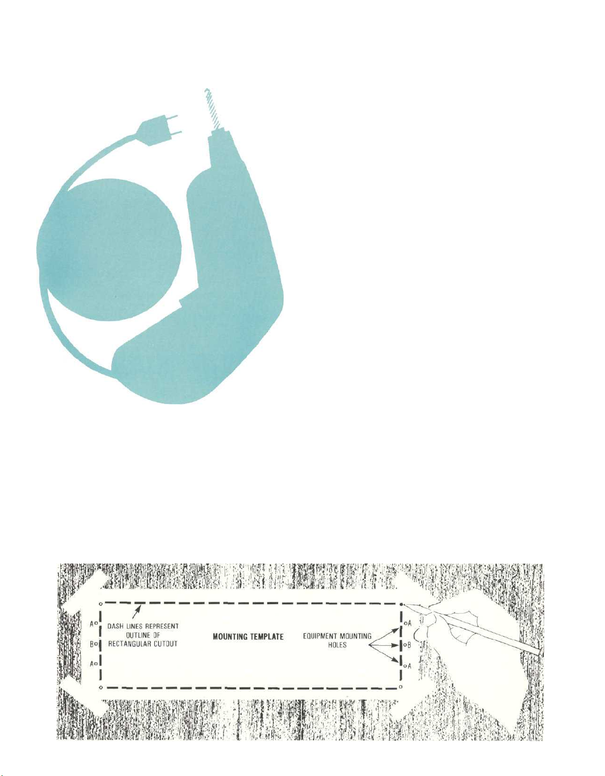
2. Mark the Cabinet Panel.
Place the mounting template in the position on the
cabinet panel where the instrument is to be install-
ed, and tape it in place. The broken lines that repre-
sent the outline of the rectangular cutout also represent the outside dimensions of the chassis. Make
sure these lines clear shelves, partitions, or any
equipment. With the template in place, first mark the
six A and B holes and the four small holes that
locate the corners of the cutout. Then, join the four
corner markings with pencil lines, using the edge of
the template as a straightedge.
3. Drill Holes
Use a drill with a 3/16 inch (5 mm) bit held perpen-
dicular to the panel and drill the six A and B holes.
4
Page 7
Then, using a drill bit slightly larger than the tip of
your saw blade, drill one hole at each of two
diagonally opposite corners. The holes should bare-
ly touch the inside edge of the penciled outline.
Before taking the next step, make sure that the six A
and B holes have been drilled.
4. Saw the Panel Cutout
Saw carefully on the inside of the penciled lines.
First make the two long cuts and then the two short
cuts. After the rectangular opening has been cut out,
use a file to square the corners and smooth any irregularities in the cut edges.
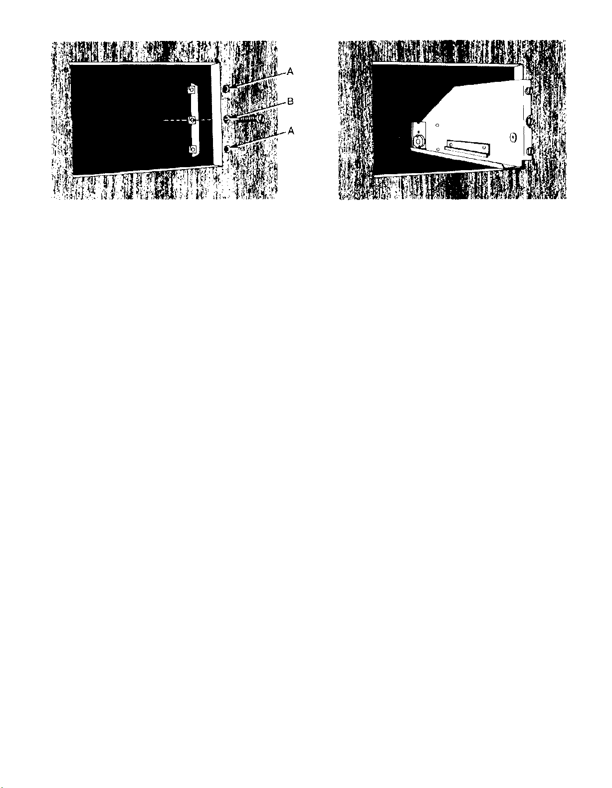
5. Install the Mounting Strips
In the hardware package you will find two mounting
strips, and two sets of machine screws. For panels
that are less than 1/2 inch (12.7 mrn) thick, use the
3/4 inch (19.1 mm) screws; for panels that are more
than 1/2 inch (12.7 mm) thick, use the 1-1/4 inch (31.8
mm) screws.
Starting at the right-hand side of the panel, insert
a screw of the proper length into the center hole in
the panel, marked B on the template. On the back of
the panel, align a mounting strip with the holes in
the panel and tighten the screw until the screwhead
is pulled into the wood.
Repeat this procedure to attach the mounting
strip to the left side of the panel.
6. Attach the PANLOC Brackets
Using two screws of the proper length in the A holes
on each side, attach the PANLOC brackets to the
cabinet panel; the short flange is mounted against
the front (face) of the cabinet panel. The screws
pass through the PANLOC bracket flange, the
cabinet panel, and then through the mounting strips
previously mounted.
7. install the Instrument
Guide the AC power cord through the panel opening
to the back of the cabinet; then, slide the instrument
into the opening carefully so that the rails on the
bottom of each side of the chassis engage the
tracks on the mounting brackets. Continue to slide
the instrument into the cabinet until it is stopped by
the intermediate position latches. Press the latches
inward, this permits the instrument to slide into the
cabinet until its front panel is flush with the cabinet
panel. Depress the PANLOC buttons at the lower left
and right corners of the instrument panel to lock the
unit firmly in the cabinet. Depressing the PANLOC
buttons again will unlock the instrument so that it
can slide outward to the intermediate position; if
you press inward on the intermediate position latches then you can remove the instrument from the
cabinet.
5
Page 8

How to Connect
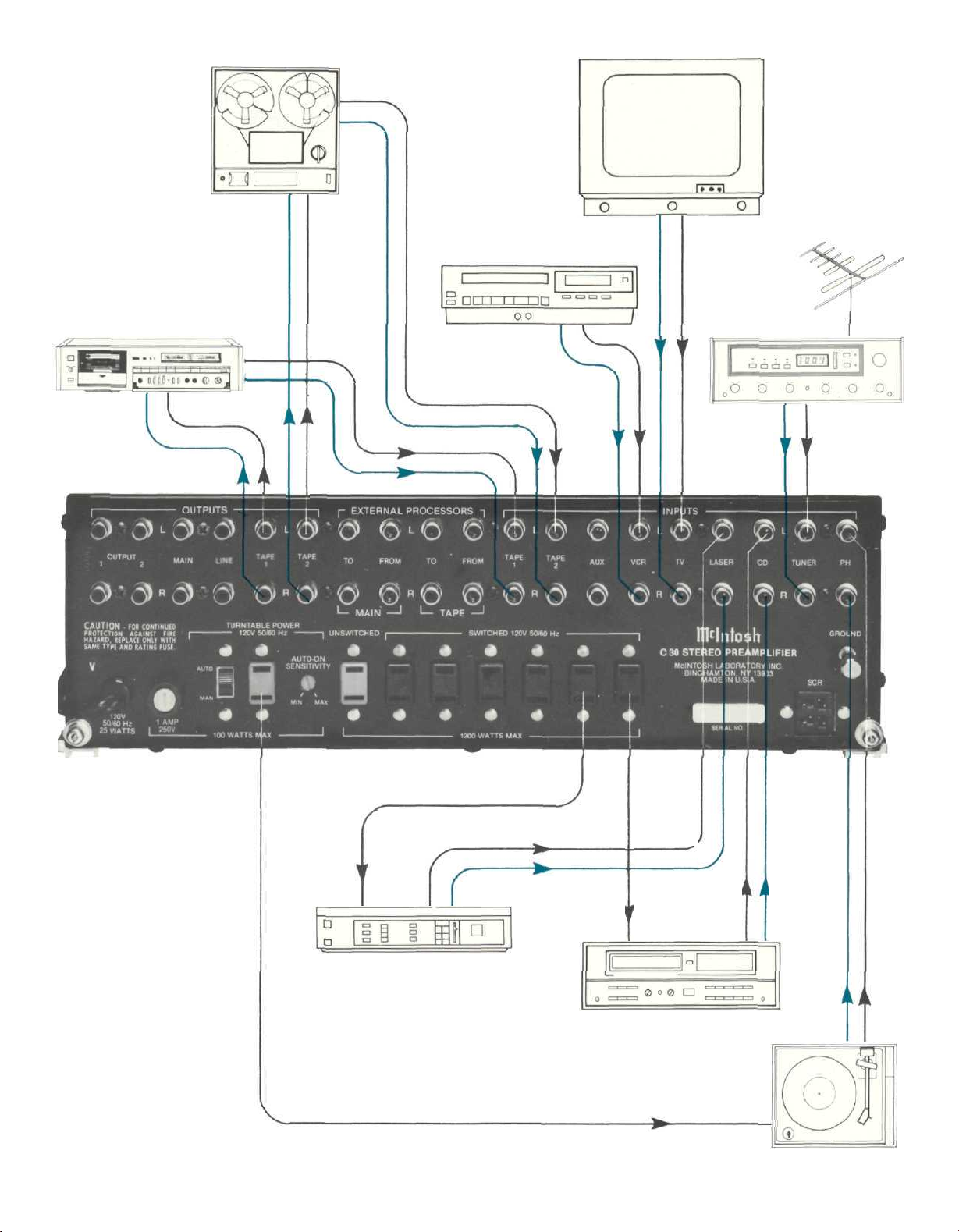
Rear panel input jacks are provided for a stereo
turntable, PH; a stereo tuner, TUNER; a compact
disc player, CD; a laser video disc player, LASER; a
TV receiver, TV; a video cassette recorder, VCR; an
auxiliary high level source, AUX, and two stereo tape
recorders, TAPE 1 and TAPE 2.
Rear panel output jacks are provided to feed two
tape recorders, TAPE 1 and TAPE 2; three 2.5 volt
main outputs, MAIN, OUTPUT 1, OUTPUT 2; and a
line (headphone circuit) output, LINE. Two sets of
jacks, EXTERNAL PROCESSORS: (one set for MAIN
and one set for TAPE,) are provided to connect noise
reduction or other signal processing units to the
main and tape record circuits.
HOW TO CONNECT A TURNTABLE:
Connect the cable from the left channel of the
turntable to the left PH jack.
Connect the cable from the right channel of the
turntable to the right PH jack. The C 30 uses
automatic shorting jacks for the phono inputs. If the
inputs are not connected, shorting plugs are not
needed.
HOW TO CONNECT A STEREO TUNER:
Connect the cable from the tuner left channel output to the left TUNER INPUT jack.
Connect the cable from the tuner right channel
output to the right TUNER INPUT jack.
HOW TO CONNECT A COMPACT DISC PLAYER:
Connect the cable from the CD player left channel
output to the left CD INPUT jack.
Connect the cable from the CD player right channel output to the right CD INPUT jack.
HOW TO CONNECT A LASER VIDEO DISC PLAYER:
Connect the cable from the laser video disc player
left channel audio output to the left LASER INPUT
jack.
Connect the cable from the laser video disc player
right channel audio output to the right LASER INPUT
jack.
HOW TO CONNECT A TV MONITOR:
Connect the cable from the left channel TV audio
output to the left channel TV INPUT jack.
Connect the cable from the right channel TV audio
output to the right channel TV INPUT jack.
HOW TO CONNECT A VCR:
Connect the cable from the left channel video
cassette recorder audio output to the left VCR INPUT jack.
Connect the cable from the right channel video
cassette recorder audio output to the right VCR INPUT jack.
HOW TO CONNECT TAPE RECORDERS
TO RECORD:
Connect a cable from the C 30 left TAPE 1 OUTPUT jack to the left high level input of a tape
recorder. Connect a cable from the C 30 right TAPE 1
OUTPUT jack to the right high level input of a tape
recorder.
Connect a second tape recorder in the same manner to the TAPE 2 OUTPUT jacks.
TO PLAYBACK OR MONITOR TAPE:
Connect a cable from a tape recorder left channel
output to the C 30 left TAPE 1 INPUT jack. Connect a
cable from a tape recorder right channel OUTPUT to
the C 30 right TAPE 1 INPUT jack.
Connect a second tape recorder in the same manner to the C 30 TAPE 2 INPUT jacks.
FRONT PANEL TAPE RECORDER JACKS:
TAPE 2 input and output connections are also
available at the TAPE 2 IN-OUT jacks on the front
panel. When a plug is inserted in the front panel
TAPE IN jack, the circuits to the rear panel TAPE 2
INPUTS will be disconnected. Inserting a plug in the
front panel TAPE OUT jack does not disconnect the
rear panel TAPE 2 OUTPUT. Thus, it is possible to
record from the front panel TAPE OUT jack and the
rear panel TAPE 2 OUTPUT jack at the same time.
However, it is not possible to listen (or monitor) from
both the front and rear TAPE 2 INPUT jacks at the
same time. Metal shielded 1/4" stereo phone plugs
may be used. Connections are tip: left signal, ring;
right signal, and sleeve: common ground.
HOW TO CONNECT AUX:
Connect the left channel cable from any high level
source (tuner, TV set, recorder, etc.) to the left AUX
INPUT jack. Connect the right channel cable to the
right AUX INPUT jack.
6
Page 9
TAPE
RECORDER 2
TAPE RECORDER 1
VIDEO CASSETTE
RECORDER
TV
FM ANTENNA
TUNER
OTHER AC SWITCHED
OUTLETS FOR TV, TAPE
RECORDERS, VCR, AND
TUNER
CONNECTIONS FOR TURNTABLE AND HIGH LEVEL PROGRAM SOURCES
AC POWER
AC POWER
LASER VIDEO DISC
PLAYER
CD PLAYER
AC POWER TO TURNTABLE
TURNTABLE
7
Page 10

HOW TO CONNECT
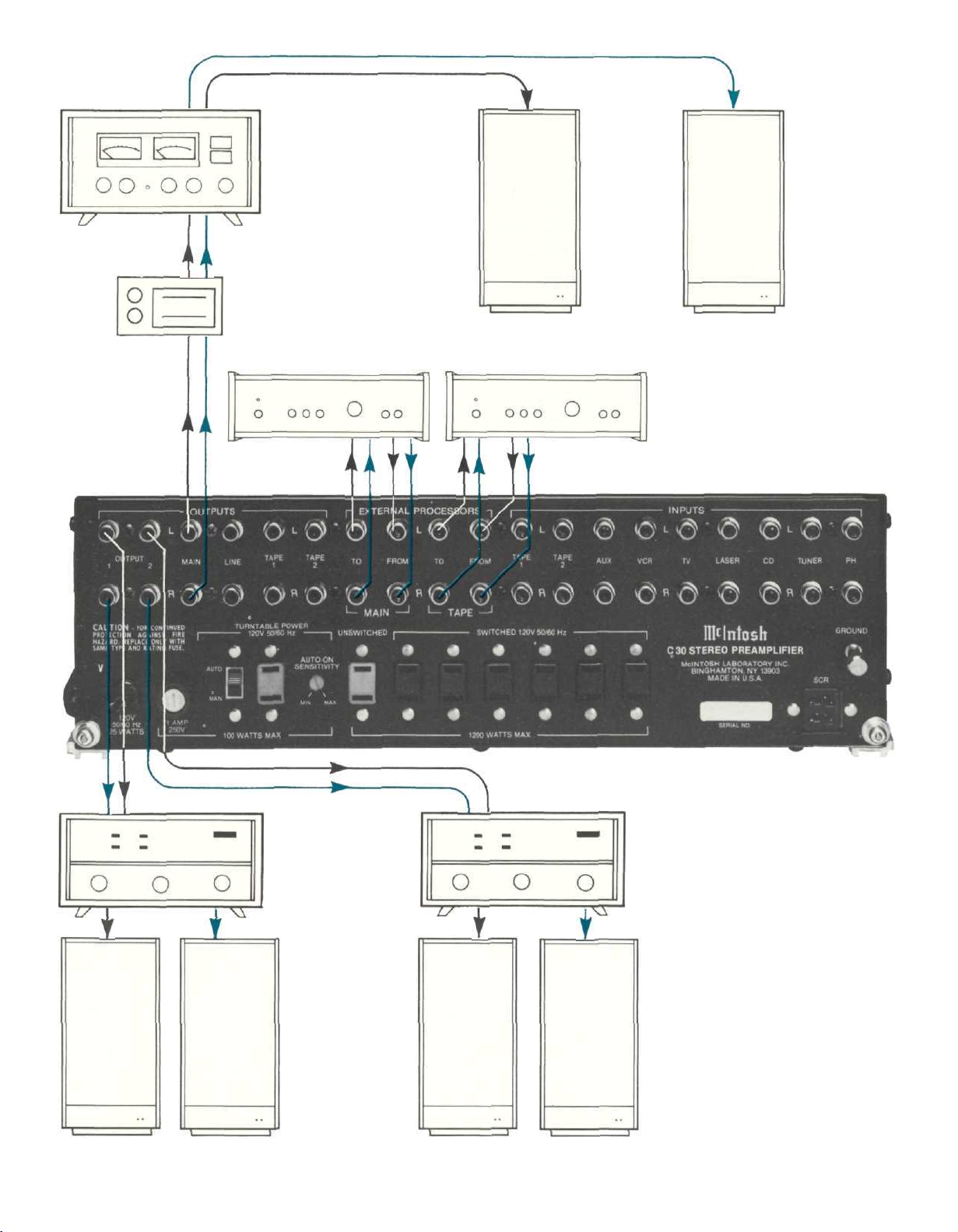
EXTERNAL SIGNAL PROCESSORS:
There are two sets of EXTERNAL PROCESSOR
jacks. One set is for the main listening circuits and
the other set is for the tape record circuits. These
jacks are used to connect to and from a noise reduc-
tion unit or to and from any other signal processing
device.
Be sure to match left to left and right to right chan-
nels when connecting external processors.
When connections are made to an EXTERNAL
PROCESSOR, the signal path is automatically
broken by the C 30 switching jacks. The SIGNAL
PROCESSOR MUST BE TURNED ON FOR THE PRO-
GRAM TO PASS THROUGH THE PREAMPLIFIER
CIRCUITS,
HOW TO CONNECT TO POWER AMPLIFIERS:
Connect a cable from the left C 30 MAIN OUTPUT
jack to the left power amplifier INPUT jack.
Connect a cable from the right MAIN OUTPUT jack
to the right power amplifier INPUT jack.
Two additional stereo power amplifiers may be
connected in the same fashion to the OUTPUT 1 and
OUTPUT 2 jacks. Audio output signal is supplied to
these jacks only when the front panel pushbutton
SPEAKER/OUTPUT No. 1 and/or No. 2 pushbuttons
are pressed. This arrangement is useful for large
systems where separate amplifiers and
loudspeakers are used at remote locations.
Additional amplifiers can serve remote areas such
as selected living areas, workshop or outdoor
recreational facilities. Other devices can be controll-
ed such as a rear channel reverberation unit.
SPEAKER CONTROL RELAY
(an optional accessory)
The SPEAKER CONTROL RELAY, or SCR, is
designed to provide both speaker control switching
and high power switched AC outlets. To control
loudspeakers, SPEAKERS 1 and 2 pushbuttons on
the front panel must be used. When this is done,
OUTPUT jacks 1 and 2 on the C 30 are normally not
used. The operation of output jacks and speaker
control will otherwise interfere with each other.
Plug the cable from the SCR into the C 30 back
panel SPEAKER CONTROL RELAY receptacle. Con-
nect the power amplifier output to the FROM
POWER AMPLIFIER terminals on the SCR. Observe
correct channel identification as well as correct
polarity. The MAIN speakers (controlled by
SPEAKER 1 pushbutton) are connected at the TO
MAIN SPEAKER terminals. The REMOTE speakers
(controlled by SPEAKER 2 pushbutton) are connected at the TO REMOTE SPEAKERS terminals.
Again, observe correct channel identification and
polarity.
SPEAKER 1 AND 2 USING THE SCR:
When pushbutton 1 is IN and pushbutton 2 is OUT,
the main speakers will be connected to the power
amplifier via the relays in the SCR. When pushbutton
1 is OUT and pushbutton 2 is IN, the remote
speakers will be connected instead. When both
pushbuttons 1 and 2 are IN, both sets of speakers
will be connected.
CAUTION: When both sets of speakers are con-
nected at the same time, their combined parallel im-
pedance must not be too low to properly match the
power amplifier output impedance. For example: if
both sets of speakers are 8 ohms, connections to
the power amplifier must be to the 4 ohm tap. If the
amplifier does not have different impedance taps, it
must be able to deliver power to a 4 ohm load as well
as an 8 ohm load.
The SCR also has two AC power outlets that pro-
vide additional capacity of 2400 watts switched by
the C 30. Use these outlets to supply AC power to
amplifiers or other components whenever the total
load to be switched by the C 30 exceeds the rating of
1200 watts. Plug the SCR heavy line cord directly into a wall outlet. When the C 30 is turned on, power
from the C 30 will energize a relay in the SCR which
connects the two SCR AC outlets directly to the wall
outlet. Do not plug the C 30 power cord into the SCR
as the preamplifier cannot function when so connected.
HOW TO CONNECT AC POWER:
Plug the preamplifier AC power cord into a 120
volt 60Hz wall outlet. A polarized attachment plug is
used. Be certain that the plug blades can be fully inserted in the outlet to prevent blade exposure. See
the caution notice on page 1.
Three types of AC power outlets are provided on
the back panel of the C 30. Six are black, one is red
and one is green.
The black outlets are switched on and off when
the C 30 is turned on and off. These are intended for
power amplifiers, CD players, equalizers and other
accessories totaling up to 1200 watts capacity.
The red outlet is on at all times. For example, a
VCR can be plugged into this outlet for recording a
TV program when the main system is not turned on.
The green AC power outlet is on at all times and is
for use only with a turntable. Do not use this outlet
for any other purpose. The turntable can be used as
a power switch as described in the following section.
8
Page 11

HOW TO USE THE TURNTABLE AS A POWER
SWITCH:
If a turntable is used with the C 30, it can be used
to turn your entire system on and off. The turntable
must be plugged into the green AC outlet at the rear
of the C 30. The AUTO/MANUAL switch also at the
rear must be in the AUTO position. When you switch
on the power to the turntable, a special sensor circuit will detect the current drain of the turntable and
will turn on the C 30 the same way the red POWER
pushbutton does. The red pushbutton must be in the
OFF or out position to do this. Read the section on
AUTO-ON SENSITIVITY on page (14) before using
this feature.
HOW TO CONNECT PROGRAM GROUNDS:
A GROUND post is provided to connect the
grounds from record changers, tape decks, etc. To
prevent hum pick-up, the left and right program
cables and the ground wire from that source should
be wound or twisted together. Make sure the ground
wire does not make any connection to the shields of
the left and right program cables as they run between the source and the input of the preamplifier.
FUSE:
A 1.0 AMP fuse protects the C 30 turntable current
sensing circuits and the green AC turntable outlet.
The fuse does not protect equipment connected to
the black AC outlets. This fuse must be replaced
with the same type and rating. A 1.0 AMP fast acting
or SLO BLO fuse may be used.
9
Page 12
POWER
AMPLIFIER
CUSTOM
ENVIRONMENTAL
EQUALIZER
(FOR MAIN SPEAKERS)
NOISE REDUCTION PROCESSORS
MAIN
MAIN SPEAKERS
TAPE
REMOTE AREA 1
(CONTROLLED BY
SPEAKER 1
PUSHBUTTON)
POWER
AMPLIFIERS
REMOTE AREA 2
(CONTROLLED BY
SPEAKER 2
PUSHBUTTON)
10
CONNECTIONS FOR
POWER AMPLIFIERS
AND LOUDSPEAKERS
USING MAIN SPEAKERS AND
ENVIRONMENTAL EQUALIZER.
ALSO SHOWN FOR REMOTE
SPEAKERS USING SEPARATE
POWER AMPLIFIERS AND
CONNECTIONS FOR EXTERNAL NOISE REDUCTION
SIGNAL PROCESSORS.
Page 13
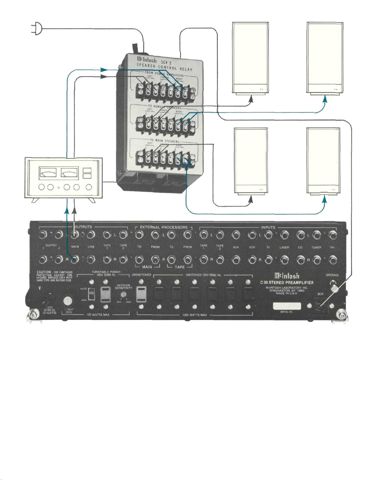
POWER
AMPLIFIER
TO AC LINE
REMOTE
SPEAKERS
(CONTROLLED BY
SPEAKER 2
PUSHBUTTON)
MAIN SPEAKERS
(CONTROLLED BY
SPEAKER 1 PUSHBUTTON)
1 1
CONNECTIONS FOR
POWER AMPLIFIERS
AND LOUDSPEAKERS
USING SPEAKER
CONTROL RELAY (SCR)
Page 14
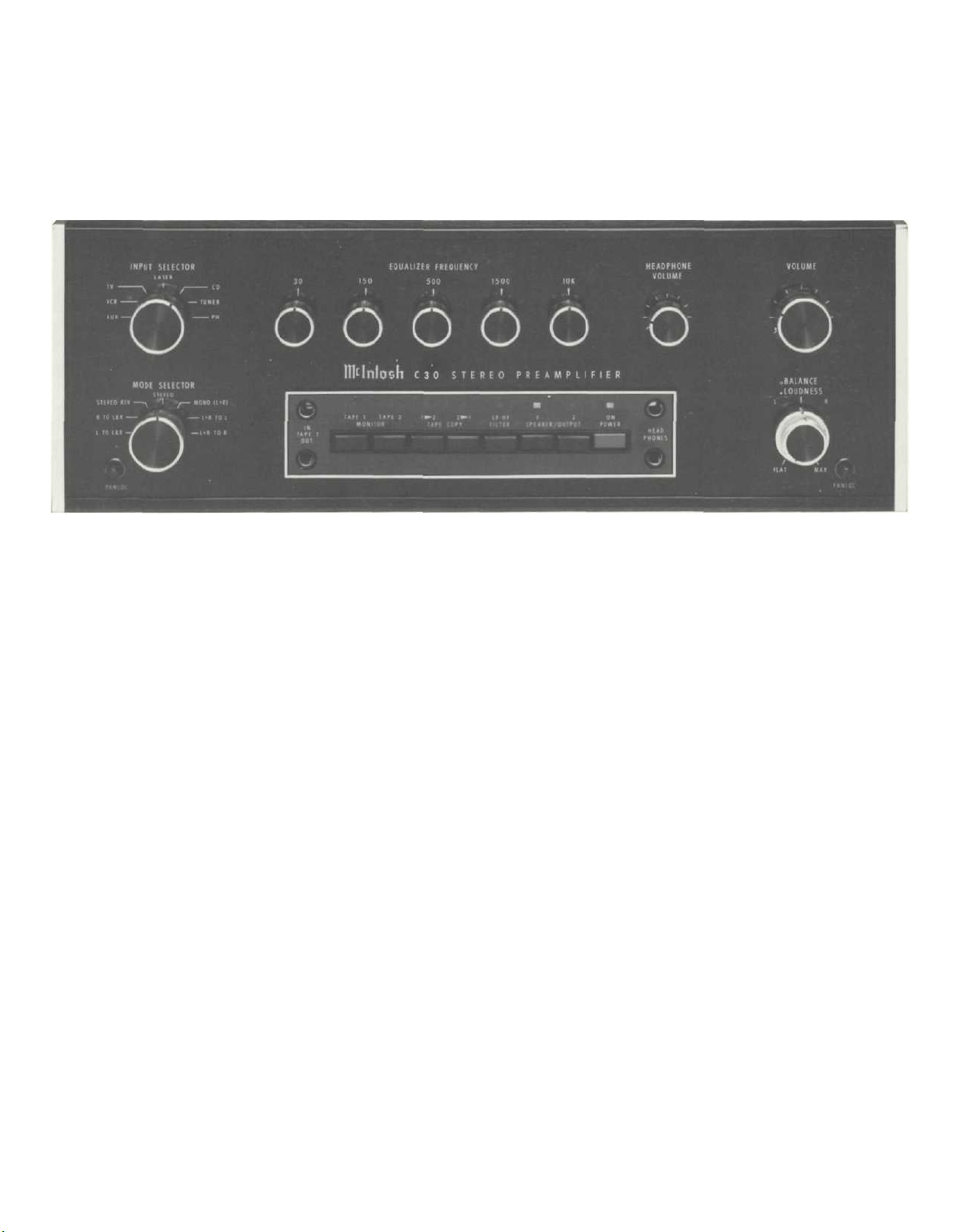
The Front Panel Controls
and How to Use Them
INPUT SELECTOR:
The INPUT selector switch is located at the upper
left on the front panel. This switch selects the input
desired for normal listening. The input program
selected will also appear at the TAPE OUTPUT jacks.
MODE SELECTOR:
The MODE SELECTOR allows you to identify each
stereo channel, create monophonic program
material, and direct program material to one channel
or the other. This switch controls the main outputs
only, and not the tape outputs.
The switch controls the program in seven ways.
L TO L&R: Connects the left input to both left and
right output circuits.
R TO L&R: Connects the right input to both left and
right output circuits.
STEREO REV: Connects the left input to the right
output circuit and the right input to the left output
circuit.
STEREO: Connects the left input to the left output
circuit and the right input to the right output circuit.
Use this STEREO position for normal listening.
MONO (L+R): Adds the left and right inputs
together to produce a monophonic program and con-
nects to both output circuits.
L + R TO L: Connects the left plus right program to
the left output circuit only.
L + R TO R: Connects the left plus right program to
the right output circuit only.
EQUALIZER FREQUENCY CONTROLS:
Each of five EQUALIZER FREQUENCY controls
raises or lowers the amplitude of a band of frequen-
cies centered on the frequency marked above the
control. Both left and right channels are affected.
The center, or flat position of the control has a detent for easy reference. At detent, the equalizer band
is removed from the preamp circuit.
Use the EQUALIZER FREQUENCY controls to
modify the sound and balance of program material.
Here are some suggestions from which to start.
ADJUSTMENT TO EQUALIZER CORRECTION
Make a deep bass
louder Raise 30
Make all bass
louder
Reinforce voices
Hum on program
Brighten violins
and trumpets
Emphasize cymbals Raise 10 K
HEADPHONE VOLUME:
This control allows independent adjustment of
the headphone volume (as well as LINE OUTPUT)
without affecting the main listen volume. The main
volume control does affect headphone volume and
must be turned up to a reasonable level prior to adjusting the headphone volume control.
VOLUME CONTROL:
The VOLUME control is a precision step control
Raise 30 and 150
Lower 150 and raise 500
Reduce 30 and 150
Raise 1500
12
Page 15

manufactured for Mclntosh Laboratory. It has 32 steps
with a 70dB range, plus volume off. Left and right
channel tracking are within a fraction of 1dB. This extreme accuracy is obtained through special electronically controlled resistance element trimming.
BALANCE AND LOUDNESS:
The BALANCE and LOUDNESS controls are concentric. The BALANCE control (large outer knob) adjusts the volume of the channels relative to each
other.
L...turning the control to the left accents the left
channel by reducing the right channel output.
R...turning the control to the right accents the
right channel by reducing the left channel output.
LOUDNESS:
The LOUDNESS control (small center knob) pro-
vides a frequency response contour which compen-
sates for the hearing characteristic of the human ear
at lower listening levels. This contour is accurately
modeled after the family of "equal loudness" curves
identified by Fletcher and Munson. At the fully
counterclockwise detented FLAT position, the
loudness contour is electrically flat. As the control
is turned clockwise, both bass and treble frequen-
cies increase in the correct proportion. The contour
is not affected by different settings of the VOLUME
control. After setting the VOLUME control for the
desired listening level, adjust the loudness control
for the preferred compensation.
TAPE PUSHBUTTONS:
IMPORTANT: When the C 30 is operated with
either MONITOR pushbutton at the IN position, the
program heard will be that from the tape recorders
only. Signal from any other source will not be heard
from the loudspeakers. To hear any other source,
make sure the MONITOR pushbuttons are OUT.
The MONITOR switches are mechanically interlocked to prevent simultaneous monitoring from
two tape recorders. If one button is at the in position, it must be pushed again to release it to the out
position before the other button can be pushed.
The C 30 is designed so that it may be used with
two tape recorders. The four pushbuttons to the left,
control the signal output of these recorders. They
permit recordings to be monitored as they are being
recorded, or copying of tapes from one recorder to
another while listening to a separate program or the
playback of either recorder.
MONITOR TAPE 1 pushbutton out: The program
source as selected by the INPUT SELECTOR is fed
to the power amplifiers and heard through the loudspeakers; pushbutton in: Signal from a tape recorder
plugged into INPUT TAPE 1 is fed to the power
amplifiers and heard through the loudspeakers.
MONITOR TAPE 2 pushbutton: Functions similar-
ly to monitor Tape 1. It also controls the program
from a tape recorder plugged into the front panel
TAPE IN and OUT jacks. When a tape recorder is
plugged into the front jacks the TAPE 2 IN jacks on
the rear panel are automatically disconnected. The
TAPE 2 outputs are connected at both front and rear
jacks.
TAPE COPY T1
T2 pushbutton in: connects the
output from tape recorder 1 to the input of tape
recorder 2 without affecting the program being
heard from the speakers. In this position a copy of
the the program on tape recorder 1 can be made on
tape recorder 2. To monitor the original, use
MONITOR TAPE 1 pushbutton and to monitor the
copy use MONITOR TAPE 2 pushbutton. When both
MONITOR pushbuttons are out, you hear the pro-
gram from the Input Selector.
TAPE COPY T2 T1 pushbutton in: connects the
output from tape recorder 2 to the input of tape
recorder 1 without affecting the program being
heard from the speakers. In this position a copy of
the tape program on recorder 2 can be made on
recorder 1. To monitor the original use MONITOR
TAPE 2 pushbutton and to monitor the copy use
MONITOR TAPE 1 pushbutton.
SPEAKER OUTPUT 1 AND 2:
The SPEAKER/OUTPUT 1 and 2 pushbuttons can
be used to control either the OUTPUT jacks 1 and 2,
or the main and remote speakers when the optional
SPEAKER CONTROL RELAY (SCR) is connected.
The SPEAKER/OUTPUT pushbuttons should not be
used to control connections to the 1 and 2 jacks and
an SCR for speaker switching at the same time. The
operation of the output jacks and the speaker control will interfere with each other.
POWER ON:
The POWER ON pushbutton shares AC power
control, through a current detecting switch circuit,
with the AC power switch on a turntable. On the rear
panel the TURNTABLE AUTO/MANUAL switch
selects the mode of operation. When the switch is in
the AUTO position and a turntable is plugged into
the green AC power outlet, the AC power to the
preamp and to the black AC power outlets can be
controlled by the turntable on/off switch. When the
turntable power switch is turned on, the preamplifier
and the SWITCHED black AC power outlets are turned on. The system will remain on until the turntable
is turned off. The POWER ON pushbutton switch
parallels the automatic turntable power control
feature. The POWER ON pushbutton is used to turn
power on and off when the turntable is not used. The
POWER ON pushbutton must be out or off for the
turntable to control the AC power.
In the MANUAL position only the POWER ON
pushbutton will turn power on or off to the
preamplifier and the black AC power outlets.
13
Page 16

FRONT PANEL PUSHBUTTON
INDICATOR LAMPS:
In all cases of use of C 30 front panel pushbuttons, the IN or ON position is indicated by a red lamp
above the switch.
TAPE RECORDER FRONT PANEL CONNECTION:
Input and output facilities are available at the
TAPE IN-OUT jacks on the front panel. These front
panel jacks make connections without having to
have access to the rear panel. When using the front
panel jacks, the rear panel TAPE 2 INPUT jacks are
disconnected automatically. A metal shielded 1/4
inch stereo phone plug is used for best shielding.
Connections follow the industry standards and are
tip: left signal, ring: right signal, and sleeve: com-
mon ground.
HEADPHONES:
The front panel HEADPHONE jack has been
designed to feed low impedance dynamic headphones. Electrostatic headphones generally require
higher power than dynamic headphones and are
connected to the output terminals on the power
amplifier.
Plug headphones into either front panel HEADPHONE jack. Adjust the front panel headphone
VOLUME control for comfortable headphone listen-
ing.
The main volume control also affects headphone
volume and must be turned up to a reasonable level
prior to adjusting the headphone volume control.
An amplifier in the C 30 provides the power that
feeds both the HEADPHONE jacks on the front
panel and the LINE OUTPUT jacks on the rear panel.
PANLOC:
Mclntosh developed PANLOC mounting brings
professional installation technique to home stereo
systems. When the PANLOC brackets are installed
in the cabinet, the unit slides easily in place to the
intermediate position. Latches on the sides of the
unit snap into position at this point. By pressing
these spring latches inward, they release and allow
the unit to slide completely into the cabinet. Then
depress the front panel PANLOC buttons to their IN
position to lock the unit into the cabinet. Depressing
the PANLOC buttons again causes them to release
to their OUT position, allowing the unit to be removed to the intermediate position. Press the intermediate latches again to allow the unit to be
removed from the cabinet.
14
Page 17
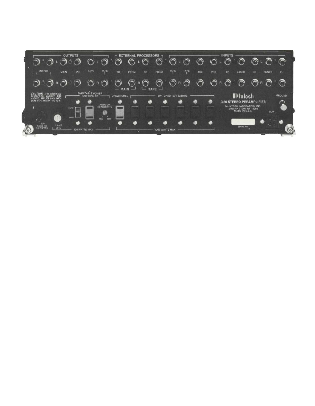
Rear Panel Controls
AUTO MANUAL SWITCH:
In the MANUAL position, the green AC outlet sup-
plys normal line voltage at all times and the turn-
table operation has no effect on the C 30 operation.
In the AUTO position, when the turntable turns on
and off, it will also cause the C 30 and the entire
system to turn on and off.
AUTO-ON SENSITIVITY:
The AUTO-ON SENSITIVITY control is located on
the right rear of the back panel. For normal operation with most turntables, the control can be left at
mid-position. Some turntables, however, have electronic circuits that draw current whether they are
turned "off" or not. The C 30 AUTO-ON SENSITIVITY
control can be used to "fine tune" for the smaller dif-
ference between on and "off" currents.
If your turntable does not control the AUTO-ON
feature of the C 30 correctly, use one of the following procedures:
1. Switch on the turntable. If the C 30 does not go
on, or goes on but does not stay on, rotate the AUTOON SENSITIVITY control clockwise towards MAX
until the C 30 goes on and stays on. Then check for
proper operation.
2. Switch off the turntable. If the C 30 does not go
off, rotate the AUTO-ON SENSITIVITY control
counterclockwise towards MIN until it does go off.
Check for proper operation.
If this doesn't correct the problem, your turntable
probably has electronic circuits that draw the same
or nearly the same current whether on or off. AUTOON control is not possible when using this turntable.
The green AC outlet can still be used but the
AUTO/MANUAL switch must be set in the MANUAL
position. The red POWER pushbutton must be used
instead.
15
Page 18

Performance Limits and Ratings
PERFORMANCE LIMITS
Performance limits are the maximum deviation
from perfection permitted for a Mclntosh instrument. We promise you that when you purchase a
new C 30 from a Mclntosh franchised dealer, it will
be capable of or can be made capable of performance at or exceeding these limits or you can return
the unit and get your money back. Mclntosh is the
only manufacturer that makes this statement.
FREQUENCY RESPONSE
+ 0,
-0.5dB
MAXIMUM VOLTAGE OUTPUT
Main and Tape Output- 10V from 20 to
20,000Hz
Line / Headphone Output- 9V (1.3V with 8 ohm
headphones) from 20 to 20,000Hz
TOTAL HARMONIC DISTORTION
.007% maximum from 20 to 20,000Hz at 2.5V rated
output
SENSITIVITY
Phono- 2mV for 2.5V rated output (0.4mV IHF)
High Level- 200mV for 2.5V rated output
SIGNAL TO NOISE RATIO, A-WEIGHTED
Phono- 90dB below 10mV input (84dB IHF)
High Level- 100dB below rated output (86dB IHF)
MAXIMUM INPUT SIGNAL
Phono- 100mV
High Level- 10V
INPUT IMPEDANCE
Phono- 47k ohms and 65pF capacitance
High Level- 22k ohms
VOLTAGE GAIN
Phono to Tape- 40dB
Phono to Main- 62dB
Phono to Headphone / Line- 68dB
(51dB with 8 ohm headphones)
High Level to Tape- 0dB
High Level to Main- 22dB
High Level to Headphone / Line- 28dB
(11dB with 8 ohm headphones)
EQUALIZATION CONTROL
Variable 12dB boost to 12dB cut at center frequencies of 30, 150, 500, 1500, 10kHz
LF-HF FILTER
Flat or roll-off at 12dB per octave below 50Hz and
above 7,000Hz
from 20Hz
(40mV IHF)
to
20,000Hz
General Information
SEMICONDUCTOR COMPLEMENT
28 Bipolar Transistors
66 Field Effect Transistors
15 Integrated Circuits
91 Diodes
1 Silicon Controlled Rectifier (SCR)
AC POWER OUTLETS
1 Turntable current-sensing, green, 100 watts
6 Switched, black, and 1 unswitched, red,
1200 watts total
POWER REQUIREMENTS
120 volts, 50/60Hz, 25 watts
Mechanical Information
SIZE
Front panel measures 16 inches wide (40.6 cm) by
5-7/16 inches high (13.8 cm). Depth of unit from
mounting surface is 13 inches (33.0 cm) including
PANLOC shelf and back panel connectors. Knob
clearance required is 1-1/4 inches (3.2 cm) in front
of the mounting panel.
FINISH
Front panel is anodized gold and black with
special gold/teal nomenclature illumination.
Chassis is black.
MOUNTING
Exclusive Mclntosh developed professional
PANLOC
WEIGHT
18 pounds (8.2kg) net, 30 pounds (13.6kg) in shipping carton
16
Page 19
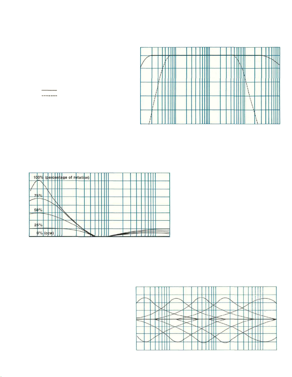
Performance Charts
0
- 4
IN dB
-12
RESPONSE
-16
-20
-8
10
FREQUENCY RESPONSE
AUX IN TO MAIN OUT
LF AND HF FILTERS
100
FREQUENCY IN HERTZ
1K
10K
100K
20
15
IN dB
10
RESPONSE
5
0
20
EQUALIZER FREQUENCY RESPONSE
CONTROLS SET AT MAXIMUM
AND MINIMUM
100
1K
FREQUENCY IN HERTZ
10K 20K
EQUALIZER FREQUENCY RESPONSE
CONTROLS SET AT MAXIMUM
AND MINIMUM
20
10
IN dB
0
RESPONSE
-10
LOUDNESS CONTROL RESPONSE
FOR VARIOUS CONTROL
POSITIONS
-20
20
1 7
100 1K
FREQUENCY IN HERTZ
10K 20K
Page 20
IN dB
RESPONSE
-10
-20
20
20
10
0
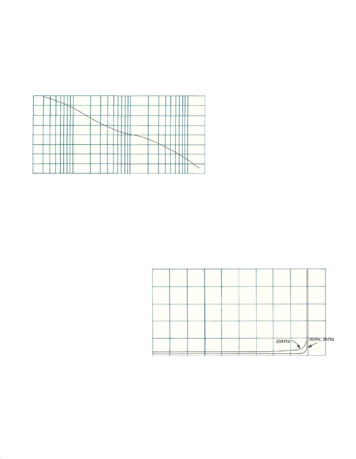
RIAA EQUALIZATION CURVE
20
100
1K
FREQUENCY IN HERTZ
10K 20K
HARMONIC DISTORTION
AUX IN TO MAIN OUT
.05
.04
.03
.02
PERCENT
IN
.01
HARMONIC DISTORTION
0
234567 9 10 12
RMS OUTPUT VOLTS
18
Page 21

Technical Description
FULL ELECTRONIC SWITCHING:
All input switching including tape, tape-to-tape
and mode is done electronically using J-FET field effect analog switches. All the front panel switches
control small amounts of DC voltage which turn the
FET analog switches on and off. The critical audio
signals are switched silently with instantaneous
muting between switch positions. No transient switching noises or pops are present with this superior
design.
PHONO AMPLIFIER:
The phono amplifier uses a high technology integrated circuit operational amplifier. Its differential
input stage has been optimized for low noise and
low distortion performance. Open loop gain of this
integrated circuit is 100,000. With high open loop
gain a large amount of negative feedback can be us-
ed around the phono amplifier to further reduce
noise and distortion. The feedback network also pro-
vides
precision
network uses 1% metal film resistors and 5% poly
film capacitors. To achieve low noise performance it
is essential that the feedback network be very low
impedance. As a consequence, the preamplifier
must be capable of operating as a power amplifier to
drive this impedance. The actual power output
capability of this preamplifier stage is more than 100
milliwatts, a great margin beyond that which is required.
Input sensitivity of the phono amplifier is 2
millivolts. The gain of the amplifier is 40dB at
1000Hz. The phono amplifier has a very wide
dynamic range. At 1000Hz the phono input circuit
will accept 100 millivolts without overload, a voltage
far greater than the output of any current magnetic
phono cartridge. Phono input overload therefore is
virtually impossible. A signal level of 10 millivolts at
the phono input at 1000Hz will produce 1 volt at the
tape output. The tape output has a source im-
pedance of 200 ohms, designed to operate into a
load impedance of 10,000 ohms or greater.
HIGH LEVEL AMPLIFIER:
At the input to the high level or loudness amplifier
the signal passes through the mode switch matrix,
then through the volume control, and into the
amplifier. In the past loudness controls have typical-
ly used simple passive circuits connected to a tap
on the volume control. As a consequence, compensation accuracy was dependent on many variables
such as volume control position and differences in
input level. The C 30 uses active circuitry. The same
type of integrated circuit operational amplifier that
is used in the phono amplifier is used here. It has
RIAA
frequency compensation.
The
two feedback loops. One feedback loop has flat
response. The other feedback loop conforms to the
Fletcher-Munson equal loudness compensation. A
potentiometer is placed between these two feedback loops making it possible to select any combination of the two from a flat response to full
loudness compensation. The overall gain of the
stage is 15dB and is not affected at mid frequencies
by the position of the loudness control.
EQUALIZER AMPLIFIER;
The equalizer amplifier uses high technology in-
tegrated circuit operational amplifiers. Its output
stage has been optimized for the best transient performance and minimum distortion. Five other operational amplifiers are each arranged in a circuit configuration that is the equivalent of series tuned circuits, one at each of the five center frequencies.
Each series tuned circuit is inserted via the control
potentiometer in either the input circuit or feedback
circuit of the operational amplifier thereby providing
a boost and cut capability of 12dB for each band of
frequencies. The overall gain of the stage is 7dB.
FILTER AMPLIFIER;
The C 30 band-pass filter amplifier affects the fre-
quency response at the two extremes of the audio
range. Each channel of the filter amplifier uses the
same type operational amplifier as in the phono
stage and high level amplifier. The resistive and
capacitive elements form a 12dB per octave active
RC filter. High frequencies roll off above 7000Hz,
and low frequencies below 50Hz. The non linear
distortion of the active filter elements in the C 30 is
very low, even at the cutoff frequencies.
HEADPHONE AMPLIFIER:
The C 30 headphone amplifier is capable of driv-
ing two pairs of dynamic headphones and the line
output with less than .007% harmonic distortion.
Maximum output is 9 volts at the line and head-
phone jacks, (1.3 volts with 8 ohm headphones). Internal impedance of the headphone amplifier is 47
ohms at each headphone output and 100 ohms at
the line output. This feature allows the line outputs
to be used with much longer than normal shielded
connecting cables without adversley affecting the
frequency response.
TURN ON DELAY:
The C 30 has a completely transient free turn on
and off. The C 30 is electronically muted for approx-
imately 2 seconds after the AC power is turned on.
This circuit also has a very short turn off time constant, which mutes the output at turn off before the
preamplifier's main power supply has a chance to
19
Page 22

discharge. Another special feature of the on-off circuit is the instantaneous return to a 2 second delay,
even if the AC pushbutton is pushed off and back on
very quickly. On and off switching transients are
never heard from the C 30.
AUTO TURN ON:
A turntable plugged into the green outlet at the
rear of the C 30 can control the on-off operation of
the C 30. Current flow to the turntable is sensed and
controls a silicon control rectifier (SCR). When the
SCR conducts a relay closes. This relay turns on
power to the C 30 and to the black AC power outlets.
A current sensing sensitivity control allows calibration of the Auto Turn-On circuit to the turntable.
Power is also controlled by the C 30 Power On
pushbutton. The Auto Turn-On circuit may be
switched off for manual power control.
POWER SUPPLY:
To eliminate possibility of hum radiation, the
power transformer is double shielded with a copper
strap and steel end housings. The transformer main
output voltage is fed to a full wave bridge rectifier.
Filtering is done with two 3300 microfarad filter
capacitors to provide the +30 volts and -30 volts
DC. The plus and minus 18 volts needed for low level
and operational stages is stabilized by integrated
circuit voltage regulators.
20
Page 23

See next page for
Block Diagram
21
Page 24
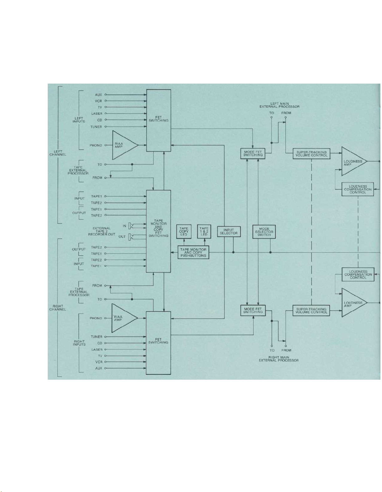
Block Diagram
22
C 30 STEREO
Page 25
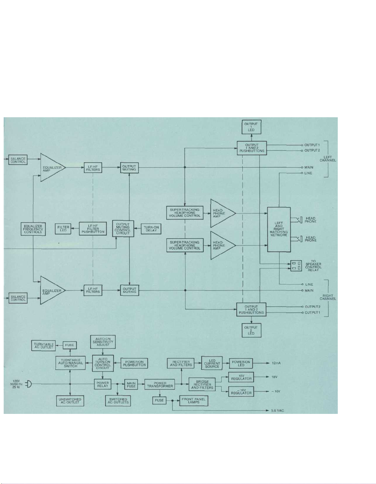
PREAMPLIFIER
23
Page 26

MclNTOSH LABORATORY INC.
2 CHAMBERS ST., BINGHAMTON, N.Y. 13903-2699
607-723-3512
The continuous improvement of its products is the policy of
Mclntosh Laboratory Incorporated who reserve the right to
improve design without notice.
Printed in U.S.A.
039493
BE042003
24
Page 27

Page 28

 Loading...