

Page 1
2A
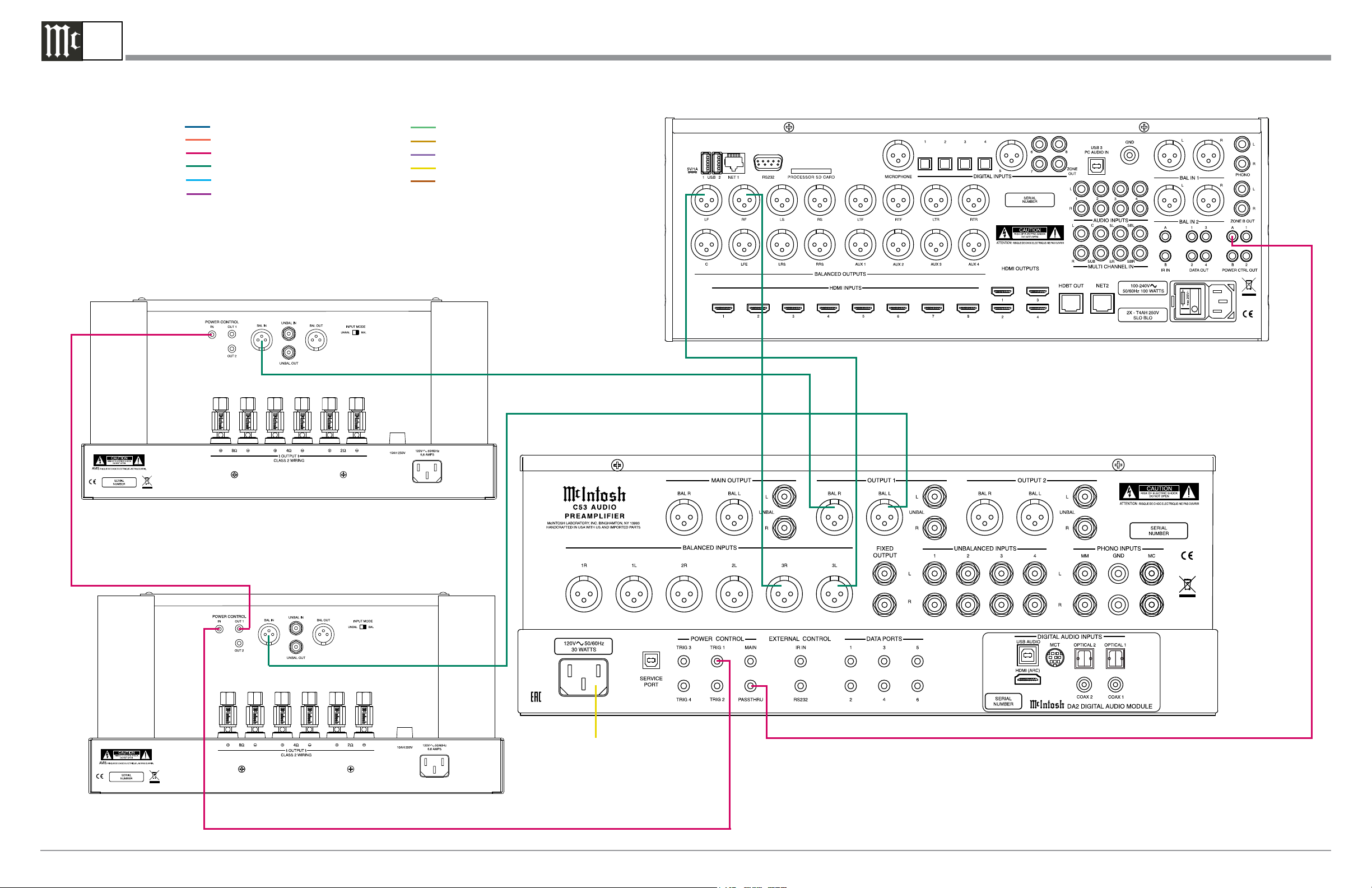
Note: Refer to the C53 Owner’s Manual page 8 for additional connection information.
C53 Audio Preamplifier Passthru Connection Diagram
Connection Legend:
Data Cable*- Digital Signal Cable Sensor/Keypad Cable - RS232 Cable Power Control Cable* - Ground Wire Audio Signal Cable - AC Power Cords -
Video Signal Cable - Loudspeaker Cable RF Signal Cable -
* 2 conductor shielded with 1/8 inch stereo mini phone plug on each end.
Power Amplifier (Right Channel) - Main Room
(Partial View)
A/V Processor
Power Amplifier (Left- Channel) - Main Room
(Partial View)
Connect to
AC Outlet
McIntosh Laboratory, Inc. 2 Chambers Street Binghamton, New York 13903-2699 Phone: 607-723-3512 FAX: 607-724-0549 Part No. 24100800
Page 2
2B
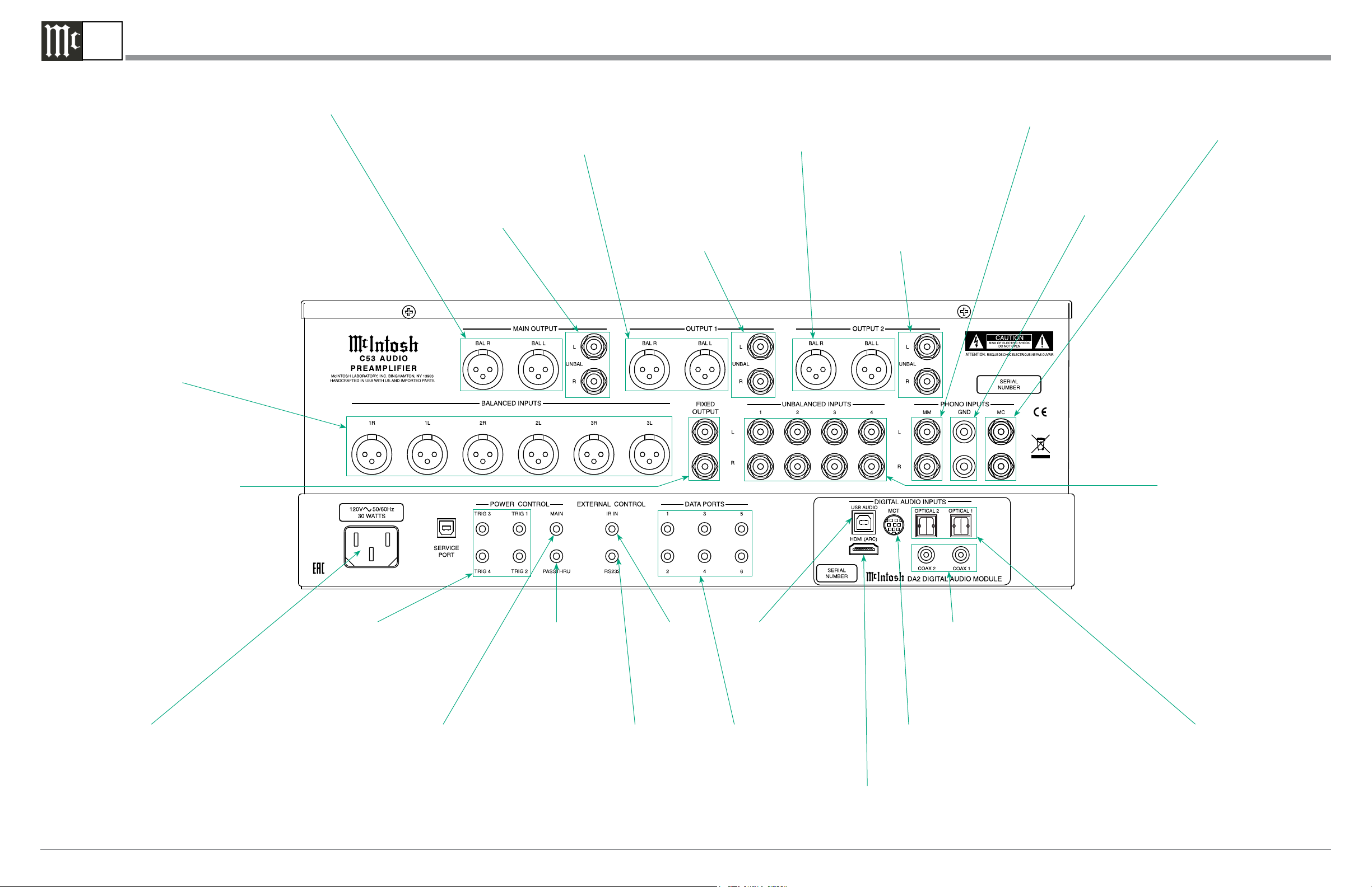
C53 Rear Panel Connections
BALANCED INPUTS 1
thru 3 accept high level
program source signals
MAIN OUTPUTS BALanced send
signals to a Power(s) Amplifier
OUTPUT 1 BALanced send
signals to Power Amplifier(s) and
is switched On/Off with the Front
Panel Output 1 Push-Button or
Remote Control Push-Button
MAIN OUTPUTS
UNBALanced send
signals to a Power(s)
Amplifier
OUTPUT 2 BALanced send
signals to Power Amplifier(s) and
is switched On/Off with the Front
Panel Output 2 Push-Button or
Remote Control Push-Button
OUTPUT 1 UNBALanced send
signals to Power Amplifier(s) and
is switched On/Off with the Front
Panel Output 1 Push-Button or Remote Control Push-Button
OUTPUT 2 UNBALanced send
signals to Power Amplifier(s) and
is switched On/Off with the Front
Panel Output 2 Push-Button or
Remote Control Push-Button
PHONO MM accepts
signals from a Moving
Magnet Phono Cartridge
GND terminals accept
a ground wire from a
turntable
PHONO MC accepts
the low level signals
from a Moving Coil
Phono Cartridge
FIXED OUTPUT
(Record Out) sends
signals to the input
of a recording device
Connect the C53 power cord
to a live AC outlet. Refer to
information on the back panel
of your C53 to determine the
correct voltage for your unit
POWER CONTROL TRIGger outputs 1 thru 4 are assignable to send
turn On/Off signals to components
POWER CONTROL MAIN
Output sends turn On/Off signals to a McIntosh Component
when the C53 is switched On/Off
PASSTHRU POWER
CONTROL Input
receives turn On/Off
signals from an Audio/
Video Control Center
RS232 connector
for connection to a
computer or other
control device
IR INput for
signals from a
compatible IR
Room Sensor
DATA PORTS are assignable
to send signals to Source
Components to allow control
with the C53 Remote Control
USB DIGITAL AUDIO
INPUT with control
signal for connection to
a computer
HDMI (ARC) DIGITAL
AUDIO INPUT with
with a digital audio signal from a TV/Monitor
COAXial DIGITAL AUDIO
INPUTS for components with a
Digital Coaxial Output sending
a digital audio signal
MCT DIGITAL AUDIO INPUT
for streaming high bandwidth
digital signals from SACD/CD
Transport Components
UNBALANCED INPUTS
1 thru 4 accept high level
program source signals
OPTICAL DIGITAL AUDIO
INPUTS for components
with a Digital Optical Output
sending a digital audio signal
McIntosh Laboratory, Inc. 2 Chambers Street Binghamton, New York 13903-2699 Phone: 607-723-3512 FAX: 607-724-0549
 Loading...