

Page 1

1A
C500 Controller Rear Panel Connections
Connect the C500C power cord to
a live AC outlet. Refer to information on the back panel of the
C500C to determine the correct
voltage for your unit
The EXTernal SENSOR
jack permits the connection of a McIntosh
IR sensor for remote
operation
TRIGGERS A (SPKR1) and B (SPKR2) Outputs send
Turn-On signals to other components connected to the
C500C. The default setting is for use with the Spkr1 and
Spkr2 Remote Control Push-buttons. Instead, Trigger
Jacks may be re-assigned to Switch On when a desired Input Source is selected. The Trigger Voltage is also selectable, 5 Volts for McIntosh Components and 5 or 12 Volts
for non-McIntosh Products
POWER CONTROL MAIN
Outputs send a turn-on signal
to a McIntosh Power Amplifier
and Source Components when
the C500C is switched On
PASSTHRU Power
Control Input receives
a turn-on signal from
a McIntosh Home
Theater Controller
DATA PORTs 1 thru 7 send signals to compatible source components and allow
remote control operation using the C500C Remote Control. The PROG/SUM Data
Port provides a summing of signals present at data ports 1-7 by default. When the
PROGramable function is activated in the Setup Controller Mode, it allows for
special control of a McIntosh MDA1000 D/A and MCD1000 CD Player
RIGHT and LEFT Power
Supplies Main Fuse holders,
refer to information on the
back panel of the C500C to
determine the correct fuse
size and rating
1
RIGHT OUTPUT Connector
tosh 23-Conductor Cable. This cable connects to the C500
RIGHT PREAMPLIFIER INPUT. It supplies the control
signals and power supply voltages for the Right Channel
Circuitry in the Preamplifier
1
WARNING: The Right and Left Output Connectors Terminals are hazardous live and present a risk of electric shock. Use ONLY the Custom Interconnect Cables sup-
accepts the custom McIn-
plied with the C500 Preamplifier and C500 Tube Preamplifier, refer to page 4 of the C500 Owner’s Manual for additional information.
McIntosh Laboratory, Inc. 2 Chambers Street Binghamton, New York 13903-2699 Phone: 607-723-3512 FAX: 607-724-0549 Part No. 04106600
LEFT OUTPUT Connector1 accepts the custom McIntosh
23-Conductor Cable. This cable connects to the C500 LEFT
PREAMPLIFIER INPUT. It supplies the control signals and
power supply voltages for the Left Channel Circuitry in the
Preamplifier
Page 2
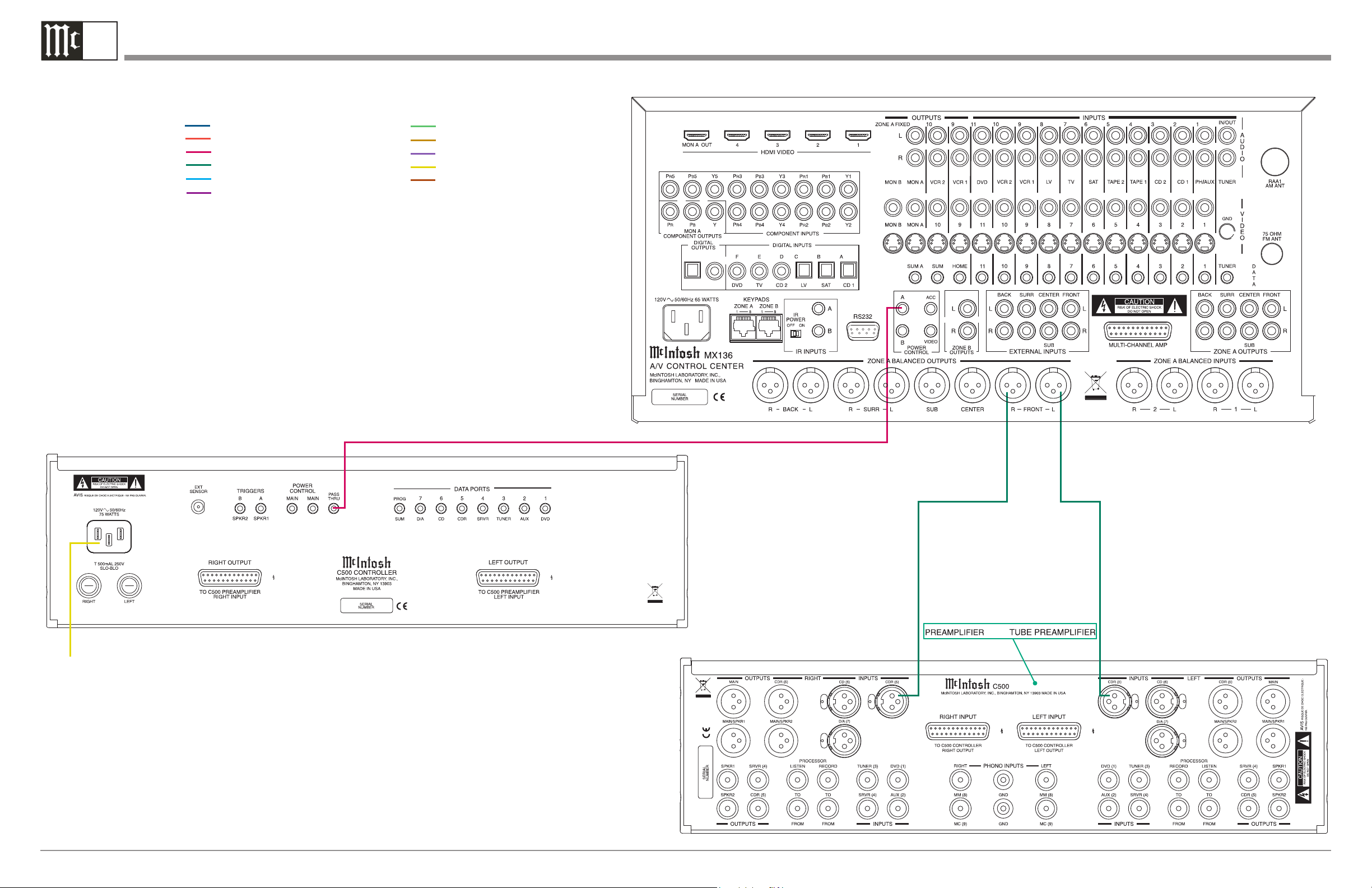
1B
C500 Passthru Connection Diagram
Note: Refer to the C500 Owner’s Manual page 13 for additional connection information.
Connection Legend:
Data Cable*- Digital Signal Cable Sensor/Keypad Cable - RS232 Cable Power Control Cable* - Ground Wire Audio Signal Cable - AC Power Cords -
Video Signal Cable - Loudspeaker Cable RF Signal Cable -
*
2 conductor shielded with 1/8 inch stereo mini phone plug on each end.
McIntosh A/C Control Center
Connect to
AC Outlet
or
 Loading...