

McIntosh C-32 Owners manual
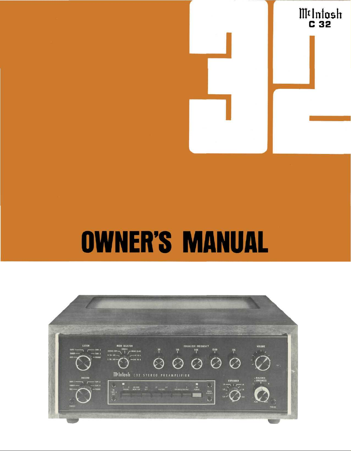
THE MclNTOSH C32 SOLID STATE STEREO PREAMPLIFIER
Reading Time: 44 Minutes
Price $1.25

WARNING: TO PREVENT FIRE OR SHOCK
HAZARD, DO NOT EXPOSE THIS UNIT TO
RAIN OR MOISTURE.
The Mclntosh you have purchased has a serial number located on
the rear panel of the chassis.
Record that serial number here
for future references. The model and serial number are important
to you for any future service.
Your C 32 Stereo Preamplifier will
give you many years of pleasant and
satisfactory performance. If you
have any questions, please contact:
CUSTOMER SERVICE
Mclntosh Laboratory Inc.
2 Chambers Street
Binghamton, New York 13903
Phone: 607-723-3512
Take Advantage of 3 years
of FREE Service...
Fill in the Application NOW.
Contents
INTRODUCTION 2
HOW TO INSTALL 2
HOW TO CONNECT 4
USING THE FRONT PANEL CONTROLS 8
USING THE PUSHBUTTONS 11
BALANCING YOUR STEREO 12
LISTENING TO YOUR STEREO 12
PERFORMANCE LIMITS AND RATINGS 13
PERFORMANCE CHARTS 14, 15
TECHNICAL DESCRIPTION 16
BLOCK DIAGRAM 19
THREE YEAR SERVICE CONTRACT
An application for a FREE THREE YEAR SERVICE CONTRACT is included with this manual.
The terms of the contract are:
1. Mclntosh will provide all parts, materials and
labor needed to return the measured performance of the instrument to the original per-
formance limits free of any charge. The
SERVICE CONTRACT does not cover any
shipping costs to and from the authorized
service agency or the factory.
2. Any Mclntosh authorized service agency
will repair Mclntosh instruments at normal
service rates. To receive the free service
under the terms of the SERVICE CONTRACT,
the SERVICE CONTRACT CERTIFICATE must
accompany the instrument when taken to
the service agency.
3- Always have service done by a Mclntosh
authorized service agency. If the instrument
is modified or damaged, as a result of unauthorized repair the SERVICE CONTRACT
will be cancelled. Damage by improper use or
mishandling is not covered by the SERVICE
CONTRACT.
4. The SERVICE CONTRACT is issued to you as
the original purchaser. To protect you from
misrepresentation this contract cannot be
transferred to a second owner.
5. For your protection Mclntosh selects only
dealers who have technical competence to
guide purchasers fairly, and provide service
when necessary. To receive the SERVICE
CONTRACT your purchase must be made
from a Mclntosh franchised dealer.
6. Your completely filled in application for a
SERVICE CONTRACT must be postmarked
within 30 days of the date of purchase of the
instrument.
7. To receive the SERVICE CONTRACT all information on the application must be filled
in. The SERVICE CONTRACT will be issued
when the completely filled in application is
received at Mclntosh Laboratory Incorporated
in Binghamton, New York.
Copyright © 1977 by Mclntosh Laboratory Inc.
1
Introduction
How to install
The Mclntosh C 32 preamplifier provides the most com-
prehensive range of functions and control options. Many
of these are new in a preamplifier. The C 32 can only
serve you best when you understand what its functions
are and what it is designed to do. Spend some time with
this manual and get to know how this preamplifier works.
The C 32 is a "dual" stereo preamplifier with a built-in
MONITOR POWER AMPLIFIER. There are two totally independent left and right stereo program lines running
through the preamplifier. One program line is the LISTEN
program line, the other is the RECORD program line. Each
program line can select its own program source from any
connected input signal—i.e. PHONO, TUNER, AUX, or
TAPES 1, 2 or 3 without interference with the other program line.
The output of the LISTEN program line is affected by
all the front panel controls (except the RECORD switch)
and is fed to the OUTPUT MAIN and/or OUTPUT 1 and 2
jacks as selected by front panel pushbuttons. The output
of the RECORD program line is not affected by front panel
controls (except the RECORD switch) and is fed to all
OUTPUT RECORD jacks.
The MONITOR AMPLIFIER program may be selected
from either the LISTEN or RECORD program lines. Sepa-
rate GAIN controls for LEFT AND RIGHT MONITOR AM-
PLIFIER are located on the top panel. The signal selected
for the MONITOR AMPLIFIER is fed to the front panel
HEADPHONE jacks and the rear panel OUTPUT LINE and
MONITOR OUTPUT connectors.
The PANLOC system of installing equipment conveniently and securely is a direct result of Mclntosh research.
By depressing the two PANLOC buttons on the front panel
of the C 32, the instrument either can be locked firmly in
place or unlocked so that the chassis can be slid forward,
giving you easy access to the top and rear panels.
The trouble-free life of an electronic instrument is
greatly extended by providing sufficient ventilation to
prevent the buildup of high internal temperatures that
cause deterioration. Allow enough clearance so that cool
air can enter at the bottom of the cabinet and be vented
from the top. With adequate ventilation the instrument
can be mounted in any position. The recommended minimum space for installation is 15 inches (38.1 cm) deep,
17 inches (43.2 cm) wide, and 6 inches (15.2 cm) high.
To install the instrument in a Mclntosh cabinet, follow
the instructions that are enclosed with the cabinet. For
any other type of installation:
1. Unpack from Carton
Remove the instrument PANLOC brackets, hardware
package, and mounting template from the carton. Remove the C 32 from its plastic bag and place it upside
down on the shipping pallet; unscrew the four plastic
feet from the bottom of the chassis.
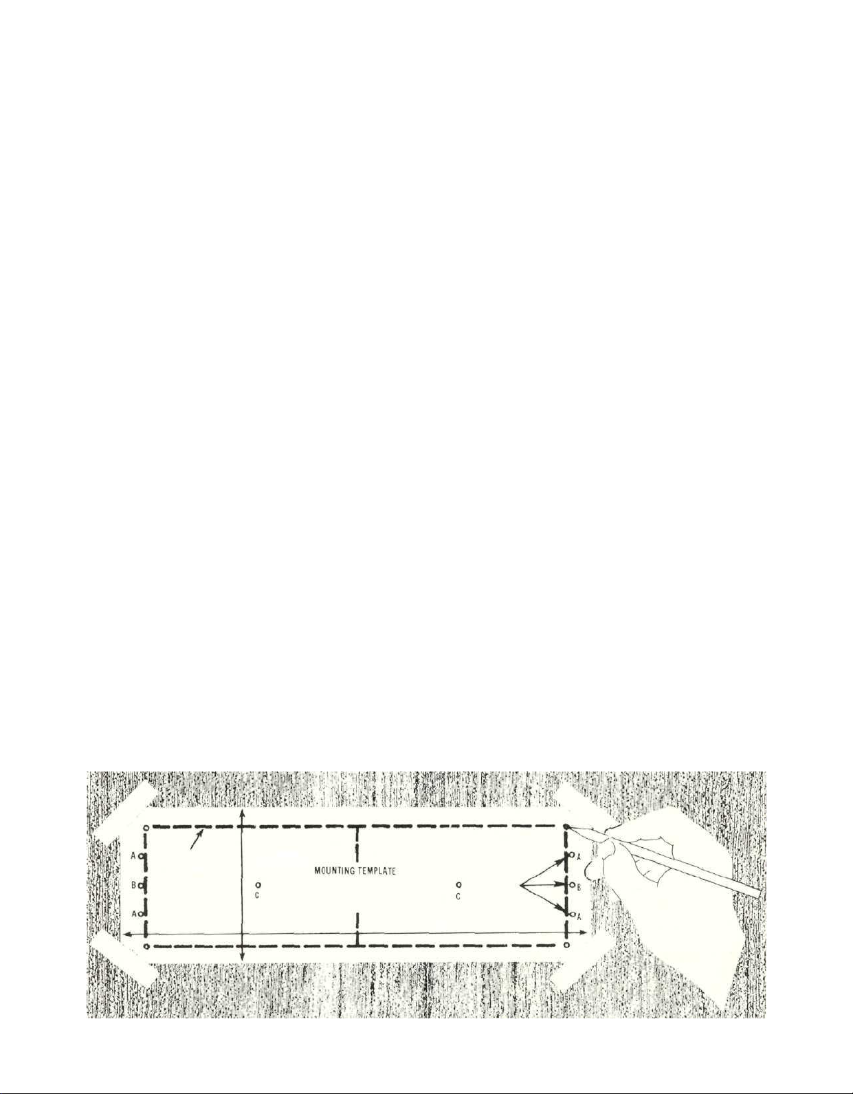
2. Mark for Position
Place the mounting template in position to cover the
area of the cabinet panel where the instrument is to be
installed, and tape it in place. The broken lines that
represent the outline of the rectangular cutout also
represent the outside dimensions of the chassis. Make
sure these lines clear shelves, partitions, or any equipment. With the template in place, first mark the six A
and B holes and the four small holes that locate the
corners of the cutout. Then, join the four corner markings with pencil lines, using the edge of the template
as a straightedge.
2

3. Drill Holes
Using a drill with a 3/16 inch bit held perpendicular to
the panel, drill the six A and B holes. Then, using a drill
bit slightly wider than the tip of your saw blade, drill
one hole at each of two diagonally opposite corners. The
holes should barely touch the inside edge of the pencilled
outline. Before taking the next step, make sure that
the six A and B holes have been drilled.
4. Saw Panel Cutout
Sawing carefully on the inside of the pencilled lines,
first make the two long cuts and then the two short.
After the rectangular opening has been cut out, use a
file to square the corners and smooth any irregularities
in the cut edges.
5. Install Mounting Strips
In the hardware package you will find two mounting
strips and two sets of machine screws. For panels that
are less than ½ inch thick, use the ¾ inch screws; for
panels that are more than ½ inch thick, use the 1¼ inch
screws.
Starting at the right-hand side of the panel, insert a
screw of the proper length into the center hole in the
panel, marked B on the template. On the back of the
panel, align a mounting strip with the holes in the panel
and tighten the screw until the screwhead is pulled
slightly into the wood.
7. Install Instrument
Guide the AC power cord through the panel opening to
the back of the cabinet; then, slide the instrument into
the opening carefully so that the rails on the bottom of
each side of the chassis engage the tracks on the mounting brackets. Continue to slide the instrument into the
cabinet until it is stopped by the adjust position latches.
Press the latches inward, this permits the instrument to
slide into the cabinet until its front panel is flush with
the cabinet panel. Depress the PANLOC buttons at the
lower left and right corners of the instrument panel to
lock the unit firmly in the cabinet. Depressing the
PANLOC buttons again will unlock the instrument so
that it can be slid forward to the adjust position;
pressing inward on the adjust position latches permits
removal from the cabinet
Repeat this procedure to attach the mounting strip
to the left side of the panel.
6. Attach PANLOC Brackets
Using two screws of the proper length in the A holes on
each side, attach the PANLOC brackets to the cabinet
panel; the short flange is mounted against the front
(face) of the cabinet panel. The screws pass through the
PANLOC bracket flange, the cabinet panel, and then
through the mounting strips previously mounted.
3

How to Connect
CONNECTING A TURNTABLE TO PHONO 1
Connect
the
cable from
table into the INPUT L PHONO 1 jack.
Connect the cable from the "right" channel of the turn-
table into the INPUT R PHONO 1 jack.
PHONO 2 is provided for the use of a second turntable.
Connect the cable from the "left" channel of the turn-
table into the INPUT L PHONO 2 jack.
Connect the cable from the "right" channel of the turn-
table into the INPUT R PHONO 2 jack.
On the rear panel are two green AC power outlets and
a slide switch marked AUTO/MANUAL. Plug the AC power
cables from the turntable into the green TURNTABLE
POWER outlets on the rear panel. When the switch is in
the AUTO position, power to the black AC power out-
lets, can be controlled by the front panel POWER switch
or by the current drawn by a turntable plugged into
the green TURNTABLE POWER outlets. The current sens-
ing green AC power outlets will control the AC power
to the entire system from the AC power on/off switch on
the turntable. When the turntable is turned off with its
own AC power switch, no current is drawn which causes
the current sensing relays in the C 32 to turn oft all AC
power to the system. With the AUTO/MANUAL switch in the
MANUAL position, AC power to the system will be controlled
by the front panel POWER pushbutton only.
Some turntables have electronic circuits that draw current
all the time. To use these turntables the AUTO/MANUAL
switch must be in the MANUAL position.
The green AC power outlets are protected with a one
ampere fuse. Any increase in the value of this fuse will
affect the operation of the sensing circuit and can cause
severe damage.
GROUND CONNECTION
A single ground post is provided. Grounds for turntables,
record changers, tape decks, etc. should be connected to
this post. The left and right program cables and the ground
wire from that source should be wound or twisted together.
To avoid hum, make sure the ground wire does not make
any connections to the shields of the left and right program
cables between the program source and the C 32.
CONNECTING A STEREO TUNER
Connect the cable from the "left" channel tuner output
to the INPUT L TUNER jack.
Connect the cable from the "right" channel tuner output
to the INPUT R TUNER jack.
AUX—Any high level program source such as a tuner,
a TV set or a tape recorder can be connected to the INPUT
AUX jacks.
CONNECTING TAPE RECORDERS
To Record:
Connect a cable from the OUTPUT L TAPE 1 jack to the
the
"left"
channel
of the
turn-
left high level input of the tape recorder.
Connect a cable from the OUTPUT R TAPE 1 jack to the
right high level input of the tape recorder
Connect second and third tape recorders in the same
fashion to the TAPE 2 and TAPE 3 outputs.
To Playback/Monitor:
Connect the cable from the left channel output of a tape
recorder to the INPUT L TAPE 1.
Connect the cable from the right channel output of a tape
recorder to the INPUT R TAPE 1.
Connect second and third tape recorders in the same
fashion to the TAPE 2 and TAPE 3 INOUT jacks.
TAPE RECORDER FRONT PANEL CONNECTION
Inputs and outputs for TAPE 3 are available at the TAPE 3
IN-OUT jacks on the front panel just left of the pushbuttons.
This allows rapid, temporary connections to TAPE 3 position
without getting at the rear panel, A metal shielded V
stereo phone plug is used for best shielding—similar to
the plugs used on low impedance headphones. Connections
follow the industry standards and are tip: left signal, ring:
right signal, and, sleeve: common ground
Connecting a Tape Recorder to the Listen Program Line
Connect a cable from the OUTPUT 1 —LEFT jack to the
left high level input of the tape recorder
Connect a cable from the OUTPUT 1 —RIGHT jack to the
right high level input of the tape recorder.
Output signal will be ted to the tape recorder when the
front panel pushbutton OUTPUT 1 is pushed in.
CONNECTING THE C 32 TO POWER AMPLIFIERS
Connect the OUTPUT MAIN jacks to the input of a
stereo power amplifier. The Left MAIN jack is connected
to the left amplifier input jack. The Right MAIN jack is
connected to the right amplifier input jack.
Two additional stereo power amplifiers may be con-
nected in the same fashion to the OUTPUT 1 and OUTPUT 2
jacks. Audio output signal is supplied to these jacks only
when front panel pushbutton SPEAKER/OUTPUT 1 and 2
pushbuttons are pressed IN. The input impedance of the
amplifiers used should be 5,000 ohms or greater.
SPEAKER CONTROL RELAY
To control loudspeakers by use of SPEAKER/OUTPUT 1
and 2 pushbuttons on the front panel an accessory Mclntosh
SCR (SPEAKER CONTROL RELAY) is needed. Plug the special
cable from the SCR control into the SPEAKER CONTROL
RELAY receptacle. The speakers are then connected to the
SCR control.
The SCR has two AC power outlets that provide addi-
tional capacity of 2400 watts. Use these outlets to supply
AC power to amplifiers or other components to be controlled by the ON OFF cycle of the C 32. Use the SCR
whenever the total load to be switched by the C 32 exceeds
its rating of 600 watts.
4
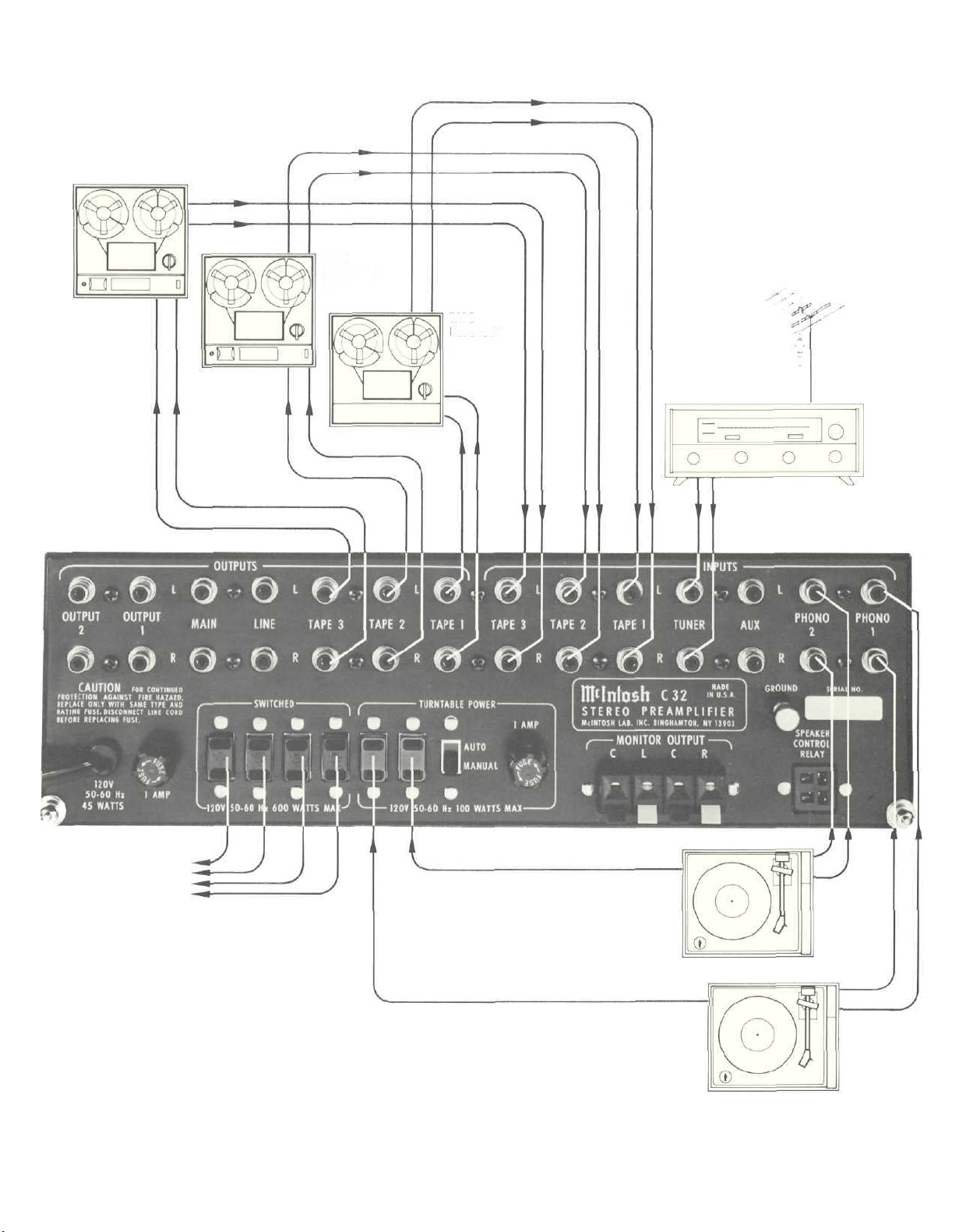
TAPE RECORDER 3
TAPE
RECORDER
2
TAPE
RECORDER
1
FM ANTENNA
TUNER
AC POWER TO
TAPE RECORDERS.
TUNERS, POWER
AMPLIFIERS.
TOTAL OF 600 WATTS.
FOR MORE AC POWER
USE THE SCR SPEAKER
CONTROL RELAY
AC POWER
TURNTABLE #2
AC POWER
TURNTABLE #1
5
 Loading...