

Page 1
Tube Preamplifier
C2300
Owner’s Manual
McIntosh Laboratory, Inc. 2 Chambers Street Binghamton, New York 13903-2699 Phone: 607-723-3512 FAX: 607-724-0549
Page 2

The lightning flash with arrowhead,
within an equilateral triangle, is
intended to alert the user to the
presence of uninsulated “dangerous voltage” within the product’s
enclosure that may be of sufficient
magnitude to constitute a risk of
electric shock to persons.
The exclamation point within an
equilateral triangle is intended to
alert the user to the presence of important operating and maintenance
(servicing) instructions in the literature accompanying the appliance.
WARNING - TO REDUCE RISK OF
FIRE OR ELECTRICAL SHOCK, DO
NOT EXPOSE THIS EQUIPMENT TO
RAIN OR MOISTURE.
IMPORTANT SAFETY
INSTRUCTIONS!
PLEASE READ THEM BEFORE
OPERATING THIS EQUIPMENT.
1. Read these instructions.
2. Keep these instructions.
3. Heed all warnings.
4. Follow all instructions.
5. Do not use this apparatus near water.
6. Clean only with a dry cloth.
7. Do not block any ventilation openings. Install in
accordance with the manufacturer’s instructions.
8. Do not install near any heat sources such as radiators, heat registers, stoves, or other apparatus
(including amplifiers) that produce heat.
9. Do not defeat the safety purpose of the polarized
or grounding-type plug. A polarized plug has two
blades with one wider than the other. A grounding type plug has two blades and a third grounding prong. The wide blade or the third prong are
provided for your safety. If the provided plug does
not fit into your outlet, consult an electrician for
replacement of the obsolete outlet.
10. Protect the power cord from being walked on or
pinched particularly at plugs, convenience receptacles, and the point where they exit from the
apparatus.
NO USER-SERVICEABLE PARTS
INSIDE. REFER SERVICING TO
QUALIFIED PERSONNEL.
To prevent the risk of electric shock, do not remove cover or
back. No user-serviceable parts inside.
11. Only use attachments/accessories specified by the
manufacturer.
12. Use only with the cart, stand, tripod, bracket, or
table specified by the manufacturer,
or sold with the apparatus. When a
cart is used, use caution when moving the cart/apparatus combination
to avoid injury from tip-over.
13. Unplug this apparatus during lightning storms or
when unused for long periods of time.
14. Refer all servicing to qualified service personnel. Servicing is required when the apparatus has
been damaged in any way, such as power-supply
cord or plug is damaged, liquid has been spilled or
objects have fallen into the apparatus, the apparatus has been exposed to rain or moisture, does not
operate normally, or has been dropped.
15. Do not expose this equipment to dripping or
splashing and ensure that no objects filled with liquids, such as vases, are placed on the equipment.
16. To completely disconnect this equipment from the
a.c. mains, disconnect the power supply cord plug
from the a.c. receptacle.
17. The mains plug of the power supply cord shall
remain readily operable.
18. Do not expose batteries to excessive heat such as
sunshine, fire or the like.
2
Page 3

Thank You
Table of Contents
Your decision to own this McIntosh C2300 Tube Preamplifier ranks you at the very top among discriminating music
listeners. You now have “The Best.” The McIntosh dedication to “Quality,” is assurance that you will receive many
years of musical enjoyment from this unit.
Please take a short time to read the information in this
manual. We want you to be as familiar as possible with all
the features and functions of your new McIntosh.
Please Take A Moment
The serial number, purchase date and McIntosh Dealer
name are important to you for possible insurance claim or
future service. The spaces below have been provided for
you to record that information:
Serial Number: __________________________________
Purchase Date: __________________________________
Dealer Name: ___________________________________
Technical Assistance
If at any time you have questions about your McIntosh
product, contact your McIntosh Dealer who is familiar
with your McIntosh equipment and any other brands that
may be part of your system. If you or your Dealer wish
additional help concerning a suspected problem, you can
receive technical assistance for all McIntosh products at:
McIntosh Laboratory, Inc.
2 Chambers Street
Binghamton, New York 13903
Phone: 607-723-1545
Fax: 607-724-0549
Customer Service
If it is determined that your McIntosh product is in need of
repair, you can return it to your Dealer. You can also return
it to the McIntosh Laboratory Service Department. For
assistance on factory repair return procedure, contact the
McIntosh Service Department at:
McIntosh Laboratory, Inc.
2 Chambers Street
Binghamton, New York 13903
Phone: 607-723-3515
Fax: 607-723-1917
Safety Instructions ............................................................
Thank You and Please Take a Moment .............................
Technical Assistance and Customer Service ....................3
Table of Contents .............................................................. 3
General Information .........................................................4
Connector and Cable Information ....................................4
Introduction .......................................................................
C2300 Features .................................................................5
Dimensions .......................................................................6
Installation ........................................................................ 7
Connections:
Rear Panel Connections (Separate Sheet) .......8 and Mc2A
How to Connect the C2300 ...............................................
Connection Diagrams (Separate Sheets) Mc1A, Mc1B and
Mc2B
Front Panel Features:
Front Panel Displays, Controls, Push-buttons and Jack . 10
Setup:
How to Operate the Setup Mode .....................................11
Default Settings ...............................................................11
Firmware Version .............................................................11
Trim Level Adjustment ....................................................11
Re-Title Inputs ................................................................. 12
Meter Illumination .......................................................... 12
Display Brightness .......................................................... 13
Power Control Triggers ................................................... 13
Accessory Power Control ................................................ 13
Tube LED ........................................................................ 13
Passthru ........................................................................... 13
Remote Control:
Remote Control Push-buttons ......................................... 14
How to Operate by Remote Control ...............................15
Operation:
How to Operate the C2300 ............................................. 16
Additional Information:
Technical Description ..................................................... 20
Specifications ..................................................................22
Packing Instruction .........................................................23
2
3
5
9
Copyright 2007 © by McIntosh Laboratory, Inc.
3
Page 4
General, Connector and Cable Information
Data
Signal
N/C
Data
Ground
PIN 2 PIN 1
PIN 3
PIN 1
PIN 2
PIN 3
Trigger
Control
Ground
N/C
Power
Control
Meter
Illumination
Control
Ground
Power
Control
Ground
N/C
General Information
1. The C2300 uses Vacuum Tubes for amplifying the
audio signal. The C2300 is designed to have only qualified Service Personnel perform any part(s) replacement
including all the vacuum tubes.
2. For additional connection information, refer to the
owner’s manual(s) for any component(s) connected to
the C2300 Tube Preamplifier.
3. The Main AC Power going to the C2300 and any other
McIntosh Component(s) should not be applied until all
the system components are connected together. Failure
to do so could result in malfunctioning of some or all of
the system’s normal operations. When the C2300 and
other McIntosh Components are in their Standby Power
Off Mode, the Microprocessor’s Circuitry inside each
component is active and communication is occurring
between them.
4. Up to two Sensors can be wired in parallel for Remote
Control of the C2300 from other rooms.
5. Balanced and Unbalanced Inputs and Outputs can be
mixed. For example, you may connect signal sources to
Unbalanced Inputs and send signals from the Balanced
Outputs. You can also use Balanced and Unbalanced
Outputs simultaneously, connected to different Power
Amplifiers.
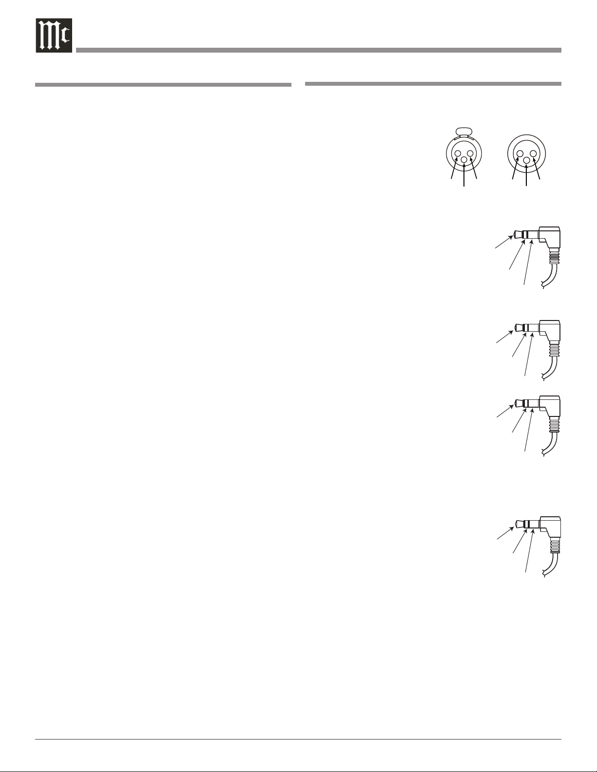
Connector and Cable Information
XLR Connectors
Below is the Pin configuration for the XLR Balanced Input
and Output Connectors on the C2300. Refer to the diagrams for connections:
PIN 1: Shield/Ground
PIN 2: + Output
PIN 3: - Output
Power Control and Trigger Connectors
The C2300 Power Control and
Trigger Output Jacks send Power
On/Off Signals when connected to
McIntosh and other Components. An
additional connection on the Main
Power Control Jack is for controlling
the illumination of the Power Output
Meters on McIntosh Power Ampli
fiers. A 1/8 inch stereo mini phone
plug is used for connection to the
Power Control and Trigger Outputs
on the C2300.
Note: The Data, Power Control and
Trigger Connecting Cable is
available from the McIntosh
Parts Department:
Data, Power Control and Trigger Cable Part No. 170-202
Six foot, shielded 2 conductor,
with 1/8 inch stereo mini phone plugs on each end.
Main Output Jack
Output 1 and 2, ACC
-
Jacks
4
Data Port Connectors
The C2300 Data Out Ports send Remote Control Signals to
McIntosh Source Components. A 1/8
inch stereo mini phone plug is used for
connection.
Page 5

Introduction
The McIntosh C2300 Tube Preamplifier is one of the finest
Tube Preamplifiers ever created. The versatile Preamplifier
provides connections for various input sources and outputs
to drive multiple Power Amplifiers. The C2300 reproduc
tion is sonically transparent and absolutely accurate. The
McIntosh Sound is “The Sound of the Music Itself.”
-
C2300 Features
• Electromagentic Input Switching with Level Trim
Adjustment
Digital Logic integrated circuits drive Electromagnetic
Switches on all Inputs and operating functions for reliable,
noiseless, distortion free switching. All eight Inputs on
the C2300 can be matched in level, so there are no abrupt
changes in volume levels between the different Inputs.
There is also a Record Monitor function for checking the
progress of a recording.
• Moving Coil and Moving Magnet Phono Inputs
The C2300 contains two different precision Phono Pre
amplifier Circuits. One for low output Moving Coil Phono
Cartridges with selectable resistance loading, the other is
for Moving Magnet Cartridges with selectable capacitive
loading. Both circuits use the latest designs to provide the
lowest possible noise and distortion. The RIAA Correction
Equalization Circuitry utilizies close tolerance resistors
and capacitors for an extremely flat frequency response.
• Balanced Inputs
The Balanced Inputs allow the connection of a source
component using long cable lengths without a loss in sound
quality.
• Precision Tracking Volume Control
Volume levels are controlled by a new Multi-Stage Precision Digitally Controlled Attenuator System with a tracking accuracy of 0.1dB.
• Variable Rate Volume and Balance Control Selection
The C2300 Tube Preamplifier’s Volume and Balance Control Circuitry provides an ideal rate of change with control
rotation.
• Assignable Tone Controls with Bypass
The C2300 remembers the Bass and Treble Control Set
tings or the Tone Circuitry Bypass Option for each input.
• Alphanumeric Fluorescent Display
The Multifunction Front Panel Display indicates the
Source Selection, Volume and Balance Levels. Setup Mode
-
-
Introduction and C2300 Features
Selections and Adjustments are also displayed. The display
intensity is adjustable.
• Precision Parts
Only the finest precision 1% tolerance resistors are used
throughout.
• Low Distortion
Distortion levels of all types are less than 0.08%. Music is
amplified with total transparency and accuracy.
• Passthru Mode
The Automatic Passthru Mode allows the C2300 to be
come part of a Multichannel Sound System for DVD-Audio, SACD and Home Theater Movies.
• Output Switching
Front panel Output Push-buttons control two Switched
Outputs that allow sending signals to two separate Power
Amplifiers.
• Remote Control with External Sensor Input
The Remote Control provides control of the C2300 op
erating functions and any McIntosh Source Components
connected to it. Enjoy your McIntosh System from other
rooms in your home by connecting external sensors.
• Power Control Output and Trigger Assignment
A Power Control connection for convenient Turn-On of
McIntosh Power Amplifiers, Source Components and
Accessories is included. Two of the Power Control Ouputs
may be assigned to activate when a given Input is selected.
• Special Power Supply
Fully regulated Power Supplies and a special R-Core Power
Transformer ensure stable noise free operation even though
the power line varies.
• Extruded Side Panels
The sides of the VP1000 are extruded aluminum panels
with a bead blast textured surface and a black anodized
finish.
• Fiber Optic Solid State Front Panel Illumination
The even Illumination of the Front Panel is accomplished
by the combination of custom designed Fiber Optic Light
Diffusers and extra long life Light Emitting Diodes
(LEDs). The glass Front Panel ensures the pristine beauty
of the C2300 will be retained for many years.
-
-
5
Page 6
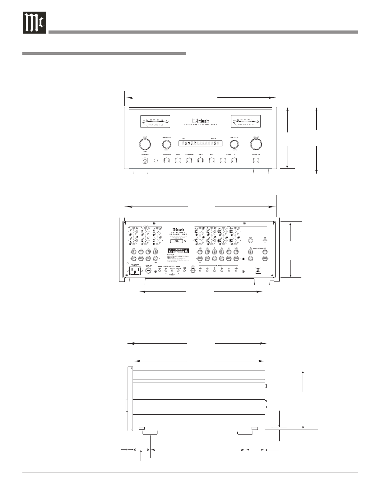
Dimensions
17-1/2"
44.45cm
6-3/8"
16.19cm
7 -5/8"
19.37cm
16-1/2"
41.91cm
3/16"
0.48cm
13 -1/4"
33.66cm
17-1/8"
43.50cm
Front View of the C2300
Rear View of the C2300
Side View of the C2300
7 -1/8"
18.10cm
13/16"
2.06cm
6-9/16"
16.67cm
10-9/16"
26.83cm
14-1/2"
36.83cm
2"
5.08cm
The following dimensions can assist in determining the
best location for your C2300. There is additional information on the next page pertaining to installing the C2300
into cabinets.
Dimensions
6
Page 7
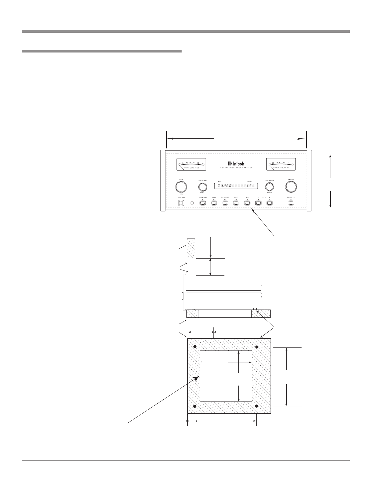
Installation
6-9/16"
16.67cm
17-3/16"
43.66cm
Cutout Opening for Custom Mounting
C2300 Front Panel
Custom Cabinet Cutout
15"
38.1cm
7-1/2"
19.05cm
15"
38.10cm
Cutout
Opening
for
Ventilation
Cutout Opening for Ventilation
Support
Shelf
Chassis
Spacers
C2300 Side View
in Custom Cabinet
C2300 Bottom View
in Custom Cabinet
4"
10.16cm
12-5/16"
31.27cm
Cabinet
Front
Panel
6"
15.24cm
Opening
for Ventilation
Note: Center the cutout Horizontally
on the unit. For purposes of
clarity, the above illustration
is not drawn to scale.
1-1/16"
2.70cm
The C2300 can be placed upright on a table or shelf, standing on its four feet. It also can be custom installed in a
piece of furniture or cabinet of your choice. The four feet
may be removed from the bottom of the C2300 when it is
custom installed as outlined below. The four feet together
with the mounting screws should be retained for possible
future use if the C2300 is removed from the custom installation and used free standing. The required panel cutout,
ventilation cutout and unit dimensions are shown.
Always provide
adequate ventilation for your C2300.
Cool operation
ensures the longest
possible operating
life for any electronic instrument. Do
not install the C2300
directly above a heat
generating component such as a high
powered amplifier.
If all the components are installed
in a single cabinet,
a quiet running
ventilation fan can
be a definite asset
in maintaining all
the system components at the coolest
possible operating
temperature.
A custom cabinet
installation should
provide the following minimum spacing dimensions for
cool operation.
Allow at least 6
inches (15.24cm)
above the top, 2
inches (5.08cm)
below the bottom
and 1 inch (2.54cm)
on each side of the Tube Preamplifier, so that airflow is not
obstructed. Allow 19-1/2 inches (49.53cm) depth behind
the front panel. Allow 1-1/8 inch (2.9cm) in front of the
mounting panel for knob clearance. Be sure to cut out a
ventilation hole in the mounting shelf according to the
dimensions in the drawing.
Installation
7
Page 8
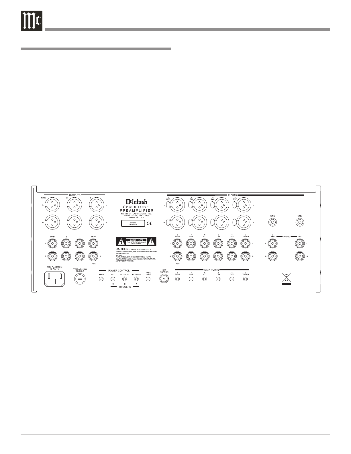
Rear Panel Connections
The identification of Rear Panel Connections for the
C2300 Tube Preamplifier is located on a separate folded
sheet contained in the Owner’s Manual Packet.
Refer to separate sheet “Mc2A” for the Rear Panel Connections.
C2300 Tube Preamplifer Rear Panel
Rear Panel Connections
8
Page 9

How to Connect the C2300
The C2300 has the ability to automatically switch power
On/Off to McIntosh Source Components via the Power
Control connections. The Data Port Connections allow for
the remote operation of basic functions using the C2300
Remote Control. With an external sensor connected to the
C2300, remote control operation of the system is possible
from another room and/or when the C2300 is located in a
cabinet with the doors closed.
The connection instructions below, together with the
C2300 Input and Output Connection Diagrams located on
the separate folded sheets “Mc1A/1B and Mc2A/2B”, is
an example of a typical audio system. Your system may
vary from this, however the actual components would be
connected in a similar manner. For additional information
refer to “Connector and Cable Information” on page 4.
Power Control Connections:
1. Connect a Control Cable from the C2300 POWER
CONTROL ACC(C) Jack to the Power Control In on
the McIntosh SACD/CD Player.
2. Connect a Control Cable from the McIntosh SACD/CD
Player Power Control Out jack to the McIntosh D/A
Converter Power Control In Jack.
3. Connect a Control Cable from the McIntosh D/A Converter Power Control Out jack to the McIntosh Tuner
Power Control In Jack.
4. Connect a Control Cable from the McIntosh Tuner
Power Control Out jack to the McIntosh Music Server
Power Control In Jack.
5. Connect a Control Cable from the C2300 POWER
CONTROL MAIN Out jack to the McIntosh Power
Amplifier Left Channel Power Control In Jack. Connect a Control Cable from the Left Channel Power Amplifier Power Control Out to the Right Channel Power
Amplifier Power Control In Jack.
6. Optionally connect a Control Cable from the C2300
POWER CONTROL OUTPUT 1 jack to the McIntosh
Power Amplifier (Secondary Room) Power Control In
Jack.
7. Connect any additional McIntosh Components in a
similar manner, as outlined in steps 1 thru 4.
Data Control Connections:
8. Connect a Control Cable from the C2300 TUNER
DATA PORTS Jack to the McIntosh TUNER1 Data In
Jack.
9. Connect a Control Cable from the C2300 CD DATA
PORT Jack to the McIntosh SACD/CD Player Data In
jack.
10. Connect a Control Cable from the C2300 SRVR DATA
PORT Jack to the McIntosh Music Server Data In jack.
11. Connect a Control Cable from the C2300 D/A DATA
How to Connect the C2300
PORT Jack to the McIntosh D/A Converter Data In
jack.
12. Connect any additional McIntosh Components in a
similar manner, as outlined in steps 8 thru 11.
Sensor Connections:
13. Connect a RG59U or RG6U Cable from the C2300
EXT SENSOR “F” Connector to the McIntosh Sensor
“F” Connector.
Audio Connections:
14. Connect an Audio Cable from the C2300 TUNER
INPUT Jacks to the McIntosh TUNER1 Fixed Output
Jacks.
15. Connect Balanced Cables from the C2300 CD INPUT
Jacks to the McIntosh SACD/CD Player Fixed Balanced Output Jacks.
Note: Unbalanced Audio Cables may be used instead of
the Balanced Cables, but not both.
16. Connect an Audio Cable from the C2300 SRVR INPUT Jacks to the McIntosh Music Server Output Jacks.
17. Connect an Audio Cable from the C2300 SRVR OUTPUT Jacks to the McIntosh Music Server Input 1 Jacks.
18. Connect an Balanced Cables from the C2300 D/A
OUTPUT Jacks to the McIntosh D/A Converter output
Jacks.
19. Connect the Audio Cables coming from the Turntable
to the C2300 MC PHONO INPUT Jacks.
Note: If the Turntable has a Moving Magnet Cartridge
connect the audio cables to the C2300 MM PHONO
INPUT instead of the MC Input.
20. Connect Balanced Cables from the C2300 MAIN
OUTPUT jacks to the McIntosh Power Amplifiers
(Main Left and Right) Input jacks.
21. Connect an Audio Cable from the C2300 OUTPUT 1
jacks to the McIntosh Power Amplifier (Secondary)
Input jacks.
22. Connect any additional McIntosh Components in a
similar manner, as outlined in steps 14 thru 21.
Optional “PassThru” Connections:
23. Connect Audio Cables or Balanced Cables from the
McIntosh MX Series A/V Control Center Front Left
and Right Channel Outputs to the CDR Input Jacks.
24. Connect a Control Cable from the C2300 PASSTHRU
to McIntosh MX Series A/V Control Center Zone A
Power Control Output.
Ground Connections:
25. Connect the Gound Cable coming from the Turntable
to the C2300 GND Binding Post.
AC Power Cords Connections:
26. Connect the C2300 and any remaining components’
AC Power Cords to a live AC outlet as illustrated.
9
Page 10

Front Panel Displays, Controls, Push-buttons and Jack
INPUT Control selects
the desired audio signals
for listening and recording. It is also used in the
setup mode for various
functions
METER indicates
the Preamplifier’s
Left Channel relative
Output Level
IR Sensor receives
commands from a
Remote Control
TRIM SELECT
allows selection
of various types
of audio settings.
It is also used in
the setup mode for
various functions
DISPLAY indicates the
Sources, Volume, other
Audio Settings, Operational Functions and
Setup Mode Settings
TRIM ADJUST
allows adjustment
of various types
audio settings. It
is also used in the
setup mode for
various functions
METER indicates the
Preamplifier’s Right
Channel relative Output
Level
VOLUME Control adjusts the listening level
for both channels
Connection for low
impedance dynamic headphones
with 1/4” (0.64cm)
stereo phone type
plug, for private
listening
TONE BYPASS with
indicator, when activated
the audio signal bypasses the Tone Controls
10
MONO with
indicator,
combines the
Left and Right
Channel signals
for Monophonic
Sound
REC MONITOR Push-button with indicator, allows
listening to the playback of
REC/SRVR Source while
the recording is in process
SETUP Mode Pushbutton with indicator,
allows the changing
of the default settings
for Inputs, Levels,
Special Functions
and the Display
OUTPUTS 1 and 2 Pushbuttons with indicators,
allow the C2300 to switch
Power Control and Audio
to two separate Stereo
Power Amplifiers
MUTE Push-button with indicator,
activates different
Muting Modes
STANDBY/ON
Push-button switch
es the C2300 ON or
OFF (Standby) and
resets the microprocessors
-
Page 11

Setup
How to Operate the Setup Modes
Your McIntosh C2300 has been factory configured for
default operating settings that will allow immediate enjoyment of superb audio without the need for further adjustments. If you wish to make changes to the factory default
settings, a Setup Feature is provided to customize the operating settings using the Front Panel Alphanumeric Display.
Refer to the C2300 Front Panel Illustration on the previous
page while performing the following steps.
Note: If the C2300 is currently, On proceed to step 2.
1. Press the STANDBY/ON Push-button to switch On the
C2300. The title TUBE WARMUP will appear on the
Front Panel Alphanumeric Display. Refer to figure 1.
Figure 1
Note: The Red LED above the STANDBY/ON Push-but-
ton lights to indicates the C2300 is connected to AC
Power.
2. Press the C2300 Front Panel SETUP Push-button. The
LED above the SETUP Push-button will illuminate
and the Front Panel Display will indicate C2300 V1.00
or higher. Refer to figure 2.
Figure 2
Note: The Front Panel Display will indicate C2300
V1.00 or higher the first time, after that it will display whatever Setup Mode was last accessed.
3. Rotate the MENU (INPUT) Control and notice the
Setup Mode goes forwards through eight different
possible adjustment selections and one informational
display.
4. To exit from a specific Setup Mode, press the SETUP
Push-button a second time. The LED above the SETUP Push-button will extinguish and the Front Panel
Display will revert back to its normal display. Refer to
figure 3.
Figure 3
Default Settings
The Default Settings Chart below indicates the Function
Name, default Setting and the page number for additional
information.
Default Settings
Function Name Setting Page No.
C2300 V_._ _ 11
TRIM TUNer 0.0 11
INPUT
3 TUN
12
METER ON 12
DISPLAY
7 13
TRIGger TUNER> - - 13
ACCessory <C> MAIN 13
TUBE LED ON 13
PASSTHRU OFF 13
Firmware Version
The C2300 functionality is controlled by internal software
that is know as Firmware. The Version of the Firmware
in the C2300 can be identified at any time by utilizing the
Setup Mode.
1. Press the SETUP Push-button to access the Setup
Mode.
2. Rotate the MENU (INPUT) Control until C2300 V1.00
or higher appears. Refer to figure 2.
3. The number after the character “V” is the Firmware
number.
4. Press the SETUP Push-button to exit the Setup Mode.
Trim Level Adjustment
Source Components can have slightly different volume
levels resulting in the need to readjust the C2300 Volume
Control when switching between different sources. The
C2300 allows the adjustment of levels for each of the
Source Inputs for the same relative volume. The Tuner and
CD Inputs are used in the following example.
Note: The range of adjustment is ± 6dB. The Tape/Record
Output Levels are unaffected by any changes in the
Level Trim Settings. The Trim adjustments made are
retained in permanent memory. They can be changed
by performing a new Trim Procedure. The Tuner Input
Volume Level can serve as a reference or choose another source frequently listened to. The reference Input
Source should be set to a Trim Level of 00.
1. Rotate the INPUT Control to select the Tuner Input
and adjust the VOLUME Control to the desired listening level.
11
Page 12

Re-Title Inputs
2. Press the SETUP Push-button to access the Setup
Mode.
3. Rotate the MENU (INPUT) Control until “TRIM
TUN 0.0” appears on the Front Panel Alphanumeric
Display. Refer to figure 4.
Figure 4
Note: If necessary, rotate the SELECT 1 (TRIM SELECT)
Control for “TUN” and rotate the SELECT 2
(TRIM ADJUST) for ”0.0”.
4. Rotate the SELECT 1 Control or use the Remote Control ◄INPUT► push-button until the display indicates “TRIM CD 0.0”.
5. Rotate the SELECT 2 Control or use the Remote
Control LEVEL or Push-buttons until Listening
Volume Level of the CD Input is the same as the Tuner
Volume Level. The figure 5 illustration indicates a
-2.5dB decrease in the CD Level.
Figure 5
The C2300 provides the ability to change the default Input
Titles to match the components in your system. In the
following example the CDR Input will be renamed and appear as AUX on the Front Panel Alphanumeric Display.
Notes: 1. One of the high level Inputs may be renamed to AUX
or swiched Off. If any input is switched Off its name
will no longer appear on the Front Panel Alphanumeric Display when using the INPUT Control, nor is
it accessible with the Remote Control.
2. When a high level input is switched Off its name will
become available to the remaining high level inputs.
3. The Phono MC and Phono MM Inputs are designed
for connection of a turntable only and thus the title
is not changeable. However, the Phono Input may be
switched Off.
1. Press the SETUP Push-button to access the Setup
Mode.
2. Rotate the MENU Control until “INPUT 3 TUN”
appears on the Front Panel Alphanumeric Display.
3. Rotate the SELECT 1 Control until “INPUT 7
CDR” appears on the Front Panel Alphanumeric Display. Refer to figure 6.
6. Rotate the SELECT 1 Control until the name of the
next Input to be adjusted is displayed.
7. Repeat steps 5 and 6 until all the Inputs with sources
connected to the C2300 have the same relative volume
levels when switching between them. Record any
changes made to the various inputs from the default
settings in the “Input Source Settings” chart below.
8. Press the SETUP Push-button to exit the Setup Mode.
Input Source Settings
Default Title New Title Trim Trigger
TUNER
DVD
D/A
CD
CDR
SERVER
MC PHONO
MM PHONO
Figure 6
3. Rotate the SELECT 2 Control until the Front Panel
Alphanumeric Display indicates “INPUT 7 AUX”.
Refer to figure 7.
Figure 7
4. Press the SETUP Push-button to exit the Setup Mode.
Meter Illumination On/Off
The Front Panel Meter Illumination may be switched On or
Off. Follow the steps below to switch the Meter Illumination Off.
1. Press the SETUP Push-button to access the Setup
Mode.
2. Rotate the MENU Control until the words METER
ON appears.
3. Rotate the SELECT 2 Control until the Front Panel
Alphanumeric Display indicates “METER OFF”.
4. Press the SETUP Push-button to exit the Setup Mode.
12
Page 13

Display Brightness
The Front Panel Alphanumeric DISPLAY Brightness may
be varied from a setting of 1 (Dim) to 7 (Bright). Follow
the steps below for reducing the Display Brightness.
1. Press the SETUP Push-button to access the Setup
Mode.
2. Rotate the MENU Control until the word DISPLAY 7
appears.
3. Rotate the SELECT 2 Control until the Front Panel
Alphanumeric Display indicates “Display 3”.
4. Press the SETUP Push-button to exit the Setup Mode.
Power Control Triggers
The OUTPUT 1(A) and OUTPUT 2(B) Power Control
Outputs are reassignable to activate only when a given
Input is selected. In the following example, the Power Control OUTPUT 1(A) Jack will be set to function as TRIGGER A for the DVD Input.
1. Press the SETUP Push-button to access the Setup
Mode.
2. Rotate the MENU Control until “TRIG TUNER >
- - ” appears on the Front Panel Alphanumeric Display.
Refer to figure 8.
Figure 8
3. Rotate the SELECT 1 Control until the display indicates “TRIG DVD > - - ”.
4. Rotate the SELECT 2 Control until the display indicates “TRIG DVD > A ”. Refer to figure 9.
Figure 9
5. Press the SETUP Push-button to exit the Setup Mode.
Setup, con’t
Figure 10
cates “ACC< C > ON”. Refer to figure 10.
Tube LED
To swich Off the Tube LED green illumination perform the
following:
1. Press the SETUP Push-button to access the Setup
Mode.
2. Rotate the MENU Control until “TUBE LED ON” appears on the Front Panel Alphanumeric Display.
3. Rotate the SELECT 2 Control until the display indicates “TUBE LED OFF”.
4. Press the SETUP Push-button to exit the Setup Mode.
Passthru
The C2300 can be part of a Multichannel Sound System
for SACD, DVD-Audio and Home Theater. The Right and
Left Front Channels from a McIntosh A/V Control Center
or Surround Decoder can “Passthru” the C2300 and onto
its associated Power Amplifier(s). The Setup Mode allows
the activation of the Passthru Mode and the Selection of
the C2300 Input (Input numbers 3 - 8 on the Rear Panel)
that will be used for the Right and Left Front Channels. In
the example below, the Right and Left Front Channels from
the Multichannel Processor/Decoder will be connected to
the CDR (7) Input Jacks on the C2300. Refer to page 9 for
additional connection information.
1. Press the SETUP Push-button to access the Setup
Mode.
2. Rotate the MENU Control until “PASSTHRU OFF”
appears on the Front Panel Alphanumeric Display.
3. Rotate the SELECT 2 Control until the display indicates “PASSTHRU 7 ”. Refer to figure 11.
Accessory Power Control
The ACC (C) Power Control Output is reassignable from
the default setting of going ON/OFF with the C2300
(Main), to being controlled by the Remote Control ACC
ON/OFF Push-buttons. To reassign it perform the following:
1. Press the SETUP Push-button to access the Setup
Mode.
2. Rotate the MENU Control until “ACC < C > MAIN”
appears on the Front Panel Alphanumeric Display.
3. Rotate the SELECT 2 Control until the display indi-
Figure 11
4. Press the SETUP Push-button to exit the Setup Mode.
13
Page 14

LED illuminates during the time a
remote command is sent to the C2300
Press to Power the
C2300 ON or OFF
Remote Control Push-Buttons
Press MODE to switch between
Stereo and Mono Modes
Turns AC Power ON or OFF to
certain McIntosh Components when
connected via the Data Port
Selects Functions for McIntosh
Home Controller and as a “shift”
key when used with the AM or FM
push-buttons to select Output (Spkr)
1 or 2
Switches OFF the
entire C2300 System
Use to select tuner presets, disc
tracks or any numbered operation
Selects Output 1, AM Tuner Operat
ing Functions and Disc Selection on
certain McIntosh Disc Players
Press TRIM and then the LEVEL
Push-buttons to select and adjust
various functions
Mutes the audio
Press to Power ON
the C2300
Press to Power OFF
the C2300
Selects Output 2, FM Tuner Operat
ing Functions and Track Selection
on certain McIntosh CD Players
-
Press to REVIEW Tuner Station
Presets and select certain functions
on a variety of McIntosh Components
Adjusts the volume level up or down
Selects On Screen Functions on a
variety of McIntosh Components
-
Selects a Disc Player, Music Server
or Tape Recorder Function and also
performs various functions on a
variety of McIntosh Components
Selects one of the nine
available Audio Sources
Press to listen to the
selected Record Out
Signal
Note: Push-buttons whose function is not identified above
Selects the FF (Fast Forward) or
REWind Mode on Disc Player,
Music Server or Tape Recorder;
tunes Up or Down the AM/FM
Dial
Scrolls through the available
C2300 Inputs
are for use with other McIntosh Products.
14
Page 15

How to use the Remote Control
How to use the Remote Control
The supplied Remote Control is capable of directly controlling the functions of contemporary McIntosh Source
Components connected to the C2300 Tube Preamplifier.
Input Source Selection
Press the appropriate Source Push-button to select the
desired program source. Sources may also be selected by
pressing the ◄INPUT► push-button.
Mute
Press the MUTE Push-button to mute audio. The Record
Signals present at the SRVR REC OUTPUT Jacks are not
affected by the MUTE function. The C2300 Front Panel
Alphanumeric Display will indicate the word MUTE.
Note: For additional information on the various Mute Modes
refer to page 18.
Mode
Press the MODE Push-button to switch from Stereo to
Mono for Monophonic listening.
Disc, Server and Tape Functions
Use these push-buttons to operate a DVD Player, CD
Player, CD Changer, Music Server or Tape Recorder.
Pause
Press Pause Pushbutton to perform various functions
on a variety of McIntosh Components. It will also pause
the playing of a disc or tape player. The Pause Push-button will also allow for quick exiting from the active menu
when in the setup mode. The Pause Push-button is also
used as an Enter Push-button with some McIntosh components.
Trim
Press the TRIM Push-button until the word “BALANCE
__” appears on the Alphanumeric display, then press the
LEVEL Up
Push-button to emphasize the Left Channel
or Down Push-button to emphasize the Right Channel.
Press the TRIM Push-button until the word “TRIM _
_ _ _ _” appears on the Alphanumeric display, then press
the LEVEL Up or Down Push-button to match the
volume level of the previously selected Input.
Note: For additional information on the other Trim Fuctions
refer to pages 16, 17 and 18.
Acc On
Press ACC ON to turn the power ON to a McIntosh Disc
Player.
Numbered Push-buttons
Press Push-buttons 0 through 9 to access tuner station pre
sets, tracks on discs or selections on a Music Server.
Disc and Track
Use the DISC and TRACK Push-buttons when a Disc
Player or Music Server is being used.
Tuner Push-buttons
Press the AM or FM Push-button to select the desired
broadcast band. Press and release the CHANnel Up
or
Down Push-button to move from station to station. Press
and hold a CHANnel Up or Down Push-button to
move continuously from station to station. Press the +10
Push-button to start the automatic brief audition of each of
the presets stored in the tuner memory. Press +10 Pushbutton a second time to stop on a station preset.
Volume
Press the Up
or Down VOLUME Push-button to raise
or lower the listening volume level.
Note: The Record Signals present at SRVR OUTPUTS are not
affected by volume changes.
Acc Off
Press ACC OFF to turn the power OFF to a McIntosh Disc
Player.
Amplifier Selection
Press the 2nd Push-button followed by the OUTPUT 1
or 2 Push-buttons either separately or together, to control
the rear panel OUTPUTS 1, 2 which can feed signals to a
Power Amplifier or other accessory component.
15
Page 16

How to Operate the C2300
Power On
The Red LED above the STANDBY/ON Push-button lights
to indicate the C2300 is connected to AC Power. To Switch
ON the C2300, press the STANDBY/ON Push-button on
the Front Panel or the PWR (Power) Push-button on the
Remote Control. The title TUBE WARMUP will appear
on the Front Panel Alphanumeric Display after Turn-On,
with the Audio Outputs muted. Refer to figures 12, 13, 14
and 21.
Source Selection
Figure 12
Figure 13
Select the desired source using the INPUT Control or
Remote Control.
Meter Illumination setting of On or Off which is the same
for all inputs.
BALANCE
Listening balance varies with different program sources,
room acoustics and listening positions relative to the
Loudspeakers. Use the Balance (Trim Function) as needed
to achieve approximately equal listening volume levels in
each Loudspeaker. To adjust the Balance perform the fol
-
lowing:
1. Rotate the Front Panel TRIM SELECT Control or press
the TRIM Push-button on the Remote Control until
“BALANCE 00” appears on the Front Panel Alphanumeric Display.
2. Rotate the TRIM ADJUST Control or press the LEVEL
+ / - Push-buttons to emphasize the Left Channel or the
Right Channel. Refer to figure 15.
Figure 15
Volume Control
Rotate the Front Panel VOLUME Control or use the
VOLUME + (Up) or - (Down) Push-buttons on the Remote
Control for the desired listening level.
Trim Functions
The C2300 has six different Trim Selections with Adjust
ments. The Trim Selections include Balance, Bass, Treble,
Tone Bypass, Input Level Matching and Meter Illumination. The Trim Settings are stored in memory independently for each Input Source Selected, the only exception being
The Front Panel Display indicates the Balance changes
in steps from 0 to 107. After approximately 3 seconds the
Alphanumeric Display returns to indicate the Source Selection and Volume Level. When the Balance is set to favor
either left or right channel, the volume number indicated
will have a “< or >” symbol on either side of the number.
Refer to figure 16. To verify the Balance setting without
Figure 16
16
Figure 14
Page 17

How to Operate the C2300
changing it, use the TRIM SELECT Control or TRIM
Push-button and select Balance.
BASS
The Intensity of the Low Frequencies in the music can be
increased or decreased by using the Trim Select and Trim
Adjust Controls. To make adjustment perform the follow
-
ing:
1. Rotate the Front Panel TRIM SELECT Control or press
the TRIM Push-button on the Remote Control until
“BASS __” appears on the Front Panel Alphanumeric
Display.
2. Rotate the TRIM ADJUST Control or press the LEVEL
+ / - Push-buttons to increase or decrease the volumne
level of the low frequencies. Refer to figure 17.
Figure 17
The Front Panel Display indicates the Bass changes in
steps from -12dB to (+)12dB. After approximately 3
seconds the Alphanumeric Display returns to indicate the
Source Selection and Volume Level.
TREBLE
The Intensity of the High Frequencies in the music can be
increased or decreased by using the Trim Select and Trim
Adjust Controls. To make adjustment perform the follow
-
ing:
1. Rotate the Front Panel TRIM SELECT Control or press
the TRIM Push-button on the Remote Control until
“TREBLE __” appears on the Front Panel Alphanumeric Display.
2. Rotate the TRIM ADJUST Control or press the LEVEL
+ / - Push-buttons to increase or decrease the volume
level of the high frequencies. Refer to figure 18.
Figure 18
The Front Panel Display indicates the Bass changes in
steps from -12dB to (+)12dB. After approximately 3 seconds the Alphanumeric Display returns to the indicate the
Source Selection and Volume Level.
activate Tone Bypass perform the following:
1. Rotate the Front Panel TRIM SELECT Control or press
the TRIM Push-button on the Remote Control until
“TONE BYPASS” appears on the Front Panel Alphanumeric Display.
2. Rotate the TRIM ADJUST Control or press the LEVEL
+ / - Push-buttons to activate the Tone Bypass or deactivate the Tone Bypass. Refer to figure 19.
Figure 19
After approximately 3 seconds the
Alphanumeric Display returns to
indicate the Source Selection and
Volume Level.
TRIM LEVEL
The Trim Level adjustments al
lows for making fine adjustments
to the previously performed Trim
Level Adjustments in the Setup
Section of this Owner’s Manual on
page 11. To make fine adjustment
to the currently selected Input
Source perform the following:
1. Rotate the TRIM SELECT
Control or press the TRIM
Push-button on the Remote
Control until “LEVEL _._”
appears on the Front Panel
Alphanumeric Display. Refer
to figure 20.
2. Rotate the TRIM ADJUST
Control or press the LEVEL
+ / - Push-buttons to adjust
the volume level from -6dB to
(+)6dB. Refer to figure 20.
After approximately 3 seconds the
Alphanumeric Display returns to
the indicate the Source Selection
and Volume Level.
Figure 21
TONE ENABLE/BYPASS
With the Tone Bypass active, the Bass and Treble Settings
for the currently selected Input Source are electronicaly
bypassed. When the Tone Bypass is switched Off the
previous settings for Bass and Treble will be restored. To
Figure 20
17
Page 18

How to Operate the C2300, con’t
METER ILLUMINATION
The C2300 Front Panel Meter Illumination may be
switched On or Off by performing the following:
1. Rotate the TRIM SELECT Control or press the TRIM
Push-button on the Remote Control until “METER
ON” appears on the Front Panel Alphanumeric Display.
2. Rotate the TRIM ADJUST Control or press the LEVEL + / - Push-buttons to switch On or Off the Meter
Illumination.
After approximately 3 seconds the Alphanumeric Display
returns to the indicate the Source Selection and Volume
Level.
Note: When the Main Power Control of the C2300 is connect-
ed to a McIntosh Power Amplifier with Remote Meter
Illumination Control the C2300 Meter Illumination
Setting of On or Off will also affect the Power Amplifer
Meter Illumination.
PHONO ADJUSTMENTS
When the Phono MC or Phono MM Input is selected an
additional TRIM SELECT FUNCTION becomes available
for adjustment. Perform the following steps to make the
Phono Trim Adjustments:
1. Select either the Phono MM or Phono MC Input using
the INPUT Control.
2. Rotate the TRIM SELECT Control or press the TRIM
Push-button on the Remote Control until “PHMM _ _
_ PF” or “PHMC _ _ _ OHM” appears on the Front
Panel Alphanumeric Display. Refer to figures 22 and
Figure 22
the AUTOTONE circuit is set to the On position in Setup
Mode, the C2300 will remember for each input whether the
Tone Bypass is active. The Front Panel LED will illuminate indicating the BYPASS Mode is active.
Mono
Press the Front Panel MONO Push-button or the MODE
Push-button on the Remote Control to combine left and
right stereo signals to a Monophonic Signal. The Front
Panel LED will illuminate indicating the MONO Mode is
active. The C2300 automatically stores into memory for
each Input, the Selection of the Stereo or Mono Mode.
Note: The signals at the SRVR OUT (REC) Jacks are not
affected.
Record Monitor
Press the REC MONITOR Push-button to hear the SERVER Playback Signal during the recording process.
Setup
Pressing the SETUP Push-button activates the Setup Mode
of the C2300 and allows customizing various operating
functions. Refer to page 11 for additional information.
Mute
Press the MUTE Push-button, on the C2300 Front Panel
or on the Remote Control, to Mute the Audio at the OUT
PUTS Connectors and HEADPHONES Output Jack. The
Front Panel Alphanumeric Display will indicate the Input
Source Name followed by the word MUTE in place of the
actual volume setting. Refer to figure 24.
Figure 23
23.
3. Rotate the TRIM ADJUST Control or press the
LEVEL + / - Push-buttons to select from the avail
able values of cartridge loading (Ohms for a Moving
Coil Cartridge or Capacitance for a Moving Magnet
Cartridge) that comes closest to the Cartridge Makers
recommend value.
After approximately 3 seconds the Alphanumeric Display
returns to the indicate the Source Selection and Volume
Level.
Tone Bypass
Press the TONE BYPASS Push-button to Bypass the Tone
Control Circuitry, providing a flat frequency response. If
18
Figure 24
Pressing the Mute Push-button a second time or adjusting the volume control (either the Front Panel or Remote
Control) will un-mute the C2300.
If the Front Panel MUTE Push-button is pressed for at
least 3 seconds, the C2300 will mute the OUTPUTS connectors, yet listening with headphones will continue until
the Mute Push-button is pressed again for 3 seconds. The
Front Panel Alphanumeric Display will indicate the Input
Source Name, Volume Setting and a Dot. Refer to figures
25 and 26.
Figure 25
Page 19

Figure 26
Output 1 and 2
Press the Front Panel OUTPUT 1 / OUTPUT 2 Push-button or by using the Remote Control and pressing the 2nd
Push-button followed by the OUTPUT 1 / OUTPUT 2
Push-button to send audio to separate Power Amplifiers
connected to the rear panel OUTPUTS 1 or 2 Jacks. It also
activates the POWER CONTROL OUTPUT 1 /OUTPUT
2 Jacks on the rear panel of the C2300. To stop the Audio
and Power Control Signals from going to the separate
Power Amplifiers press the same Push-button(s) a second
time.
Headphones Jack
Connect a pair of dynamic headphones with a 1/4”
(0.635cm) stereo phone type plug to the Headphones Jack
for private listening.
How to Operate the C2300, con’t
Reset of Microprocessors
In the unlikely event the controls of the C2300 stop functioning, the microprocessors can be reset by performing
the following:
1. Press and hold in the STANDBY/ON Push-button for
approximately five seconds and then release the pushbutton.
2. Press the STANDBY/ON Push-button, the C2300 will
resume normal operation.
Note: This can be performed with the C2300 On or in the
Standby Mode.
Output Meters
The C2300’s Output Meters indicate the Output Voltage
available at the MAIN and OUTPUT 1 & 2 Jacks to drive
Power Amplifiers. Refer to figure 27. The Meters are cali
brated in dB
(decibels) and
respond to all
the peaks contained in the
musical information. They
Figure 27
indicate to an
accuracy of at least 95% of a single cycle from a 2000Hz
tone burst.
The Meter Electronic Circuitry “Time Stretches” the Meter
Drive Signal so the Meter Pointer pauses just long enough
for the human eye to see it and is followed by a moderate
decay rate.
How To Make A Recording
1. Select the Source Input Signal you wish to record.
2. Adjust the record level using the recorder volume con
-
trol and proceed with the recording process.
3. To listen to the playback of the program source just
recorded, press the RECord MONITOR Push-button.
Note: The C2300 SRVR (REC) OUTPUTS are not affected
by the VOLUME or BALANCE controls.
19
Page 20

Technical Description
The McIntosh engineering staff has created a Tube Preamplifier without compromise, using the most advanced
McIntosh circuit design concepts. Many months of design,
testing and measuring were required. Extensive controlled
listening tests, the ultimate form of measuring, were made
before the final design was accepted.
Silent Audio Switching
All signal switching in the C2300 is done by Electro-Mag
netic devices. Electro-Magnetic Switching is a proven
technology that uses the latest in materials and manufacturing methods. Each switch consists of a glass tube that
is filled with an inert oxygen-free atmosphere and sealed
with tiny leads protruding from either end. These leads
extend into the tube and overlap one another with a separation of a few thousandths of an inch. The leads are made
from a ferrous material that is influenced by a magnetic
field. They are first plated with gold as a base material,
then with rhodium and finally ruthenium. Ruthenium is
the best contact material known. Refer to figure 28.
The glass assembly is then placed
in the center of a multilayer coil
of copper wire. The entire assembly is molded together in a tough
shock absorbing material. The
switch and coil connectors extend
from the bottom in the form of
Figure 28
printed circuit board terminals.
When a DC voltage is applied to the coil, current flows
and creates a magnetic field. The force of the field causes
the leads to bend and contact one another inside the sealed
glass tube. The inert gas eliminates corrosion of the contacts and insures a low resistance, distortion free switch.
All inputs, outputs, and data ports are controlled by
logic circuits in the C2300. The logic is changed by Front
Panel Push-buttons or by a microprocessor IR decoder.
This microprocessor IR decoder is programmed with exclusive McIntosh software. It receives data from the Front
Panel or Sensors and provides the command signals for
input switching, data switching, tone control and volume
control.
Phono Circuitry
McIntosh has long been known for its expertise in low
noise discrete amplifier circuits. The MC Amplifier con
sists of two stages, which together have a gain of 60dB at
1000Hz. The first stage (pre-preamplifier) is a new design
Moving Coil Preamplifier using special ultra low noise circuitry with out the need for a step-up transformer. It offers
the ability to change the input impedance from 25 ohms to
1000 ohms in six steps to match a wide variety of Moving
Coil Cartridges. The C2300 utilizes a double filtered pow
er supply design, just for the Moving Coil Preamplifier.
The second (compensation) amplifier stage uses
12AX7A tubes. Its input stage has been optimized for low
noise and low distortion performance. With high open loop
gain, negative feedback is used around the Phono Ampli-
-
fier to further reduce noise, distortion and has a very wide
dynamic range. The feedback network also provides precision RIAA frequency compensation. The output is buffered by a unity gain amplifier for low output impedance.
The MM Phono Amplifier uses 12AX7A tubes. Its
input stage has been optimized for low noise and low
distortion performance. It offers the ability to change the
load capacitance from 50 pF to 750 pF in 50pF steps to
match a wide variety of Moving Magnet Cartridges. With
high open loop gain, negative feedback is used around the
Phono Amplifier to further reduce noise, distortion and
has a very wide dynamic range. The feedback network also
provides precision RIAA frequency compensation. The
output is buffered by a unity gain amplifier for low output
impedance.
Tone Control Circuitry
A control attenuator inserts a series tuned circuit into
either the feedback or input section of the tone amplifier.
The level is set by a digitally controlled electronic attenu
ator. This provides a 12dB boost or cut in 1dB steps at the
frequency of the tuned circuit. The Bass turn-over frequency is 200Hz. The Treble turn-over frequency is 2kHz. The
overall gain of the stage is 0dB when the tone is adjusted to
flat. The TONE BYPASS switch removes all tone control
circuits from the signal path.
Volume Adjustments
The most frequently operated control on a Preamplifier
is the Volume Control. So it is no surprise that McIntosh
has devoted a substantial amount of time in pursuit of the
“Perfect Volume Control System”.
Conventional Mechanical Controls have poor tracking
especially when it comes to maintaining channel balance
and after a period of time they tend to introduce noise into
the audio signal, as they are rotated. The one desirable
thing they have is the rate of change in volume for degrees
of rotation, known as the audio taper. Using Electronic
Circuitry for controlling the volume can be designed to be
free from noise and maintain channel balance, however
the audio taper produced by the typical Electronic Volume
-
-
20
Page 21

Technical Description
Control Circuit is unacceptable for use in the C2300, as
it does not match the classic McIntosh Volume Control
Audio Taper. The C2300 incorporates electronic circuitry
together with sophisticated firmware to produce electronically the classic McIntosh Volume Control Audio Taper,
while maintaining the channel balance and freedom from
control noise.
The Volume Control on the Front Panel of the C2300 is
actually a special digital optical encoder. As the Volume
Control is rotated, a beam of Infra Red Light is picked up
by two internal sensors as a series of digital pulses. Refer
to the exploded view in figure
Optical Disc
29. The number of and time
between pulses are counted by
a Microprocessor which in turn
Infrared
LED
controls the McIntosh designed
Precision Electronic Attenuator that provides 213 steps in
Sensors
0.5dB increments and maintains
the channel balance to within +
Figure 29
0.1dB.
With most Preamplifiers the Volume Control is placed
ahead of the Amplifying Circuitry providing large dynamic range and freedom from input overload however, background noise level is higher at lower settings of the volume
control. By placing the Volume Control after the Amplify-
ing Circuitry there is lower background noise however,
a reduction in dynamic range and input overload is the
result. The only correct way to design a high performance
Preamplifier is with two volume controls. This provides
the benefits of wide dynamic range, freedom from Input
overload and a background noise level that actually goes
down as the volume control setting is reduced. The special
controlling circuitry for this dual volume control design is
known as the McIntosh “Dynamic Control Multiplexer”.
Meter and Circuitry
McIntosh solved the problems with ordinary meters in
the C2300. By developing electronic circuits the meters
are made to respond to short intervals with an accuracy
of 95%! To permit the eye to see such high speed motion,
the electronic circuits that drive the meter pointer are time
stretched. Special logarithmic circuitry allows the meter
to indicate a 60dB plus range, without resorting to a Meter
Range Switch.
Power Supply Circuits
To compliment the design of the C2300 there are fully
regulated power supplies. The special “R” core transform
ers supplies the necessary voltage/current for the low and
high voltage regulated circuitry.
-
C2300 Block Diagram
21
Page 22

Specifications
20
20k
50
100
200
500
1k
2k
5k
10k
0
+6
-6
+12
-12
dB
Hz
Specifications
Frequency Response
+0, -0.5dB from 20Hz to 20,000Hz
+0, -1dB from 10Hz to 100,000Hz
Total Harmonic Distortion
0.08% from 20Hz to 20,000Hz
Rated Output (Main)
2.5V Unbalanced, 5V Balanced
Maximum Voltage Output
8V RMS Unbalanced, 16V RMS Balanced
Sensitivity (for rated output)
High Level, 450mV unbalanced, 900mV balanced
Phono MM, 4.5mV
Phono MC, 0.45mV
Signal To Noise Ratio (A-Weighted)
High Level, 93dB
Phono, 80dB
Input Impedance
High Level, 20K ohms unbalanced, 40k ohms balanced
Phono MM, 47K ohms; 50 to 750pF, in 50pF steps
Phono MC, 25, 50, 100, 200, 500 or 1,000 ohms; 100pF
Maximum Input Signal
High Level, 5V Unbalanced, 10V Balanced
Phono MM, 50mV
Phono MC, 5mV
Voltage Gain
High Level to SRVR(REC) Output: 0dB
High Level to Main Output: 15dB
Phono MM to Record Output: 40dB
Phono MC to Record Output: 60dB
Output Impedance
220 ohms
Headphone Load Impedance
16 ohms to 250 ohms
Tube Compliment
MM Phono Circuitry: 2 - 12AX7A
MC Phono Circuitry: 2 - 12AX7A
High Level Circuitry: 2 - 12AX7A
Power Requirements
100 Volts, 50/60Hz at 75 watts
110 Volts, 50/60Hz at 75 watts
120 Volts, 50/60Hz at 75 watts
220 Volts, 50/60Hz at 75 watts
230 Volts, 50/60Hz at 75 watts
240 Volts, 50/60Hz at 75 watts
Standby Power, less than 2 watts
Note: Refer to the rear panel of the C2300 for the correct
voltage.
Overall Dimensions
Width is 17-1/2 inches (44.45cm)
Height is 6 inches (15.24cm) including feet
Depth is 18 inches (45.72cm) including the Front Panel,
Knobs and Cables
Weight
29.5 pounds (13.41 kg) net, 44.9 pounds (20.41 kg) in ship
ping carton
Shipping Carton Dimensions
Width is 25 inches (63.5cm)
Depth is 27 inches (68.6cm)
Height is 12 inches (30.5cm)
-
22
C2300 Bass and Treble Control Curves
Page 23

Packing Instructions
Packing Instructions
In the event it is necessary to repack the equipment for
shipment, the equipment must be packed exactly as shown
below. It is very important that the four plastic feet are attached to the bottom of the equipment. This will ensure the
proper equipment location on the bottom pad. Failure to do
this will result in shipping damage.
Use the original shipping carton and interior parts only
if they are all in good serviceable condition. If a shipping
carton or any of the interior part(s) are needed, please
call or write Customer Service Department of McIntosh
Laboratory. Refer to page 4. Please see the Part List for the
correct part numbers.
Quantity Part Number Description
1 033888 Shipping carton only
4 033887 End cap
1 033697 Inside carton only
1 034414 Top pad (foam)
1 034301 Bottom pad
4 017937 Plastic foot
4 100159 #10-32 x 3/4” screw
4 404080 #10-7/16” Flat washer
23
Page 24

McIntosh Laboratory, Inc.
2 Chambers Street
Binghamton, NY 13903
The continuous improvement of its products is the
policy of McIntosh Laboratory Incorporated who
reserve the right to improve design without notice.
Printed in the U.S.A.
McIntosh Part No. 04102700
 Loading...