

McIntosh C22CE User Manual
CONTENTS
Performance Specifications 3
Notes 3
Rear Panel 4
Front Panel and Trim Parts List 4
Section Locations 5-6
Block Diagram 5-6
Interconnection Diagram 6-9
Input/Output (Left and Right) 10-12
Amplifier 11-14
Control and Balance Control 14-18
Treble 19
Bass 20
Speaker Switch 21
AC Power Supply 22
DC Power Supply 23
Repacking Instructions 24
Mclntosh Laboratory, Inc. 2 Chambers Street, Binghamton, New York 13903 Printed


Performance Specifications
FREQUENCY RESPONSE
+ 0, -0.5dB from 20Hz to 20,000Hz
RATED OUTPUT
2.5V at MAIN and SWITCHED 1 and 2, and
BALANCED OUTPUTS
MAXIMUM VOLTAGE OUTPUT
More than 8V at all outputs
TOTAL HARMONIC DISTORTION
0.002% maximum IHF, 0.2% maximum from 20Hz
to 20,000Hz at rated output
SENSITIVITY
Phono: 2.2mV for 2.5V rated output, (0.45mV IHF)
High Level: 250mV for 2.5V rated output, (50mV
IHF)
SIGNAL-TO-NOISE RATIO, A-WEIGHTED
Phono: 80dB below 10mV input
High Level: 90dB below rated output
VOLTAGE GAIN
Phono To Tape: 41 dB at 1000Hz
Phono To Main: 61 dB at 1000Hz
High Level To Tape: 0dB
High Level To Main: 20dB
INPUT IMPEDANCE
Phono: 47K ohms and 65pF Capacitance
High Level: 22K ohms
TONE CONTROLS
Bass and Treble stepped, 20dB boost to 20dB cut
AC POWER OUTLETS
4 switched and 1 unswitched, Total capacity 1400
watts
POWER REQUIREMENTS
120V, 50/60Hz, 37 watts
DIMENSIONS
Front Panel: 16 inches (40.6cm) wide by 5-7/16
inches (13.8cm) high. Chassis depth behind mounting panel, including clearance for connectors: 14
inches (35.6cm). Knob clearance required in front of
mounting panel: 1-1/2 inches (3.8cm).
FINISH
Anodized gold and black front panel, chassis is black.
WEIGHT
16 pounds (7.3Kg) net, 25 pounds (11.4Kg) in
shipping carton
1. The four types of heavy lines on the schematics
denote the primary signal path in the following
manner:
= LEFT CHANNEL
= RIGHT CHANNEL
= LEFT BALANCED
= RIGHT BALANCED
2. Unless otherwise noted, all voltages indicated on
the schematics are measured under the following
conditions:
a. AC input at 120 volts, 50/60Hz.
b. All voltages are ±10% with respect to
ground. A high impedance (10 megohm)
voltmeter must be used.
3. Unless otherwise specified:
a. Resistor values are in ohms.
b. Capacitor values are in microfarads (uF).
4. The voltages enclosed in a box are signal voltages
that are measured with a 2.2mV, 1kHz signal
connected to both channels at the PHONO 1
INPUT JACKS.
Notes
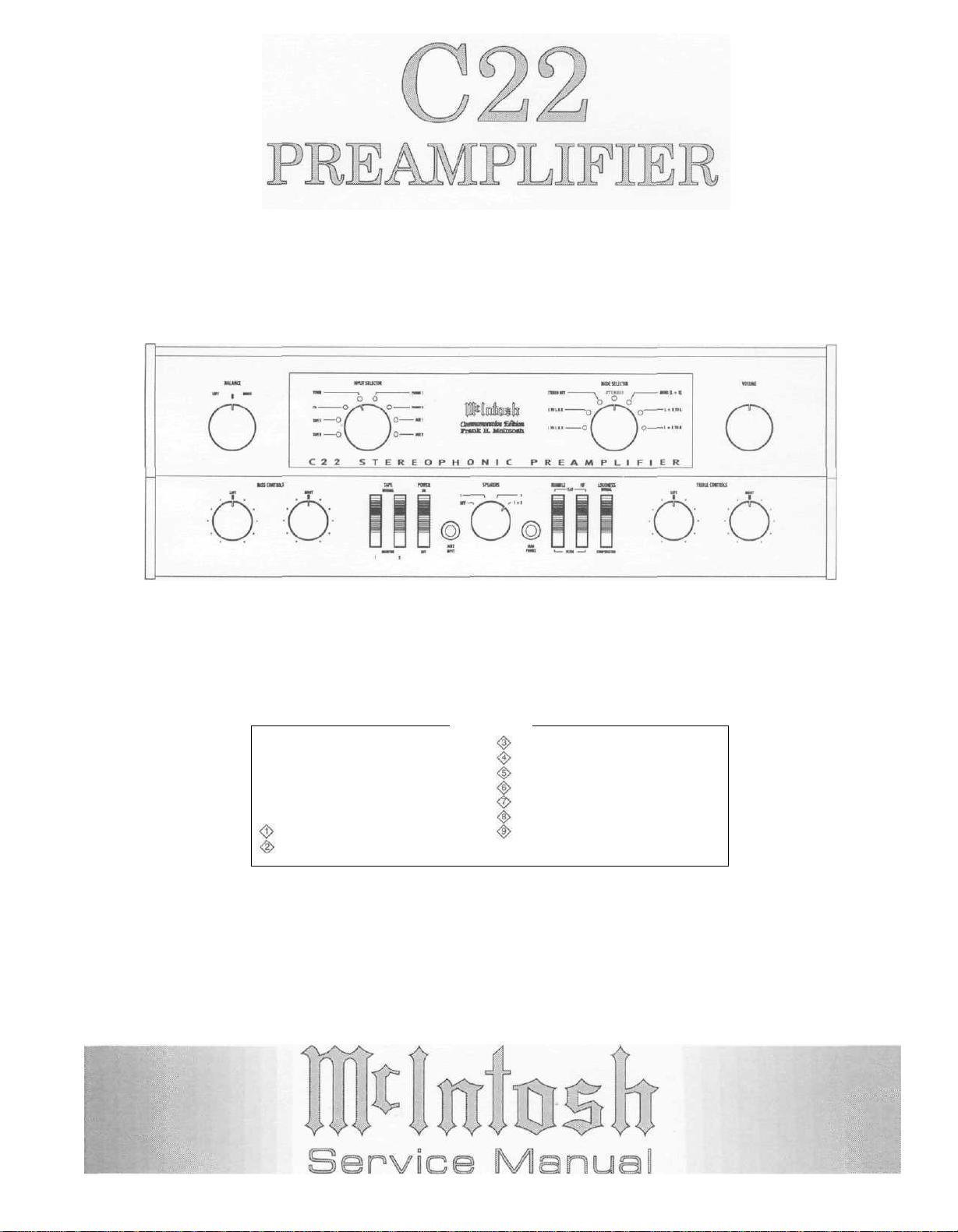
FRONT PANEL CONTROLS are set at:
BALANCE CENTER DETENT
BASS and TREBLE CENTER DETENT
INPUT SELECTOR PHONO 1
LOUDNESS NORMAL
MODE STEREO
POWER ON
VOLUME CLOCKWISE
TAPE MONITOR 1 and 2 NORMAL
RUMBLE and HF FILTERS FLAT
SPEAKERS 1&2
5. On PC Board Drawings, Square Pad Indicates:
a. Polarized Capacitors - Positive
b. Diode - Cathode
c. Others - Pin 1
6. WARNING:
Parts marked with the symbol have critical
characteristics. Use ONLY replacement parts
recommended by the manufacturer.
3
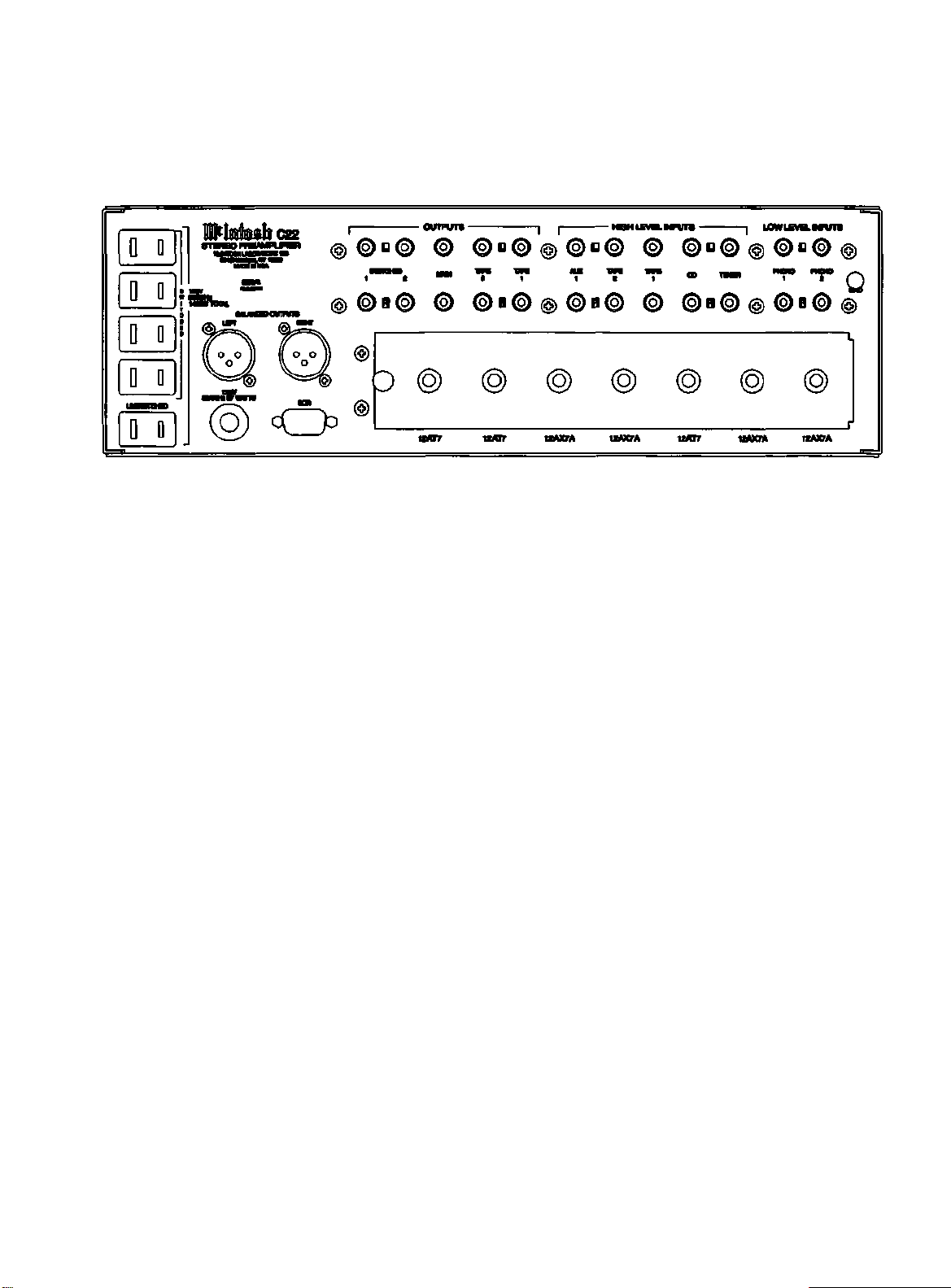
Fig. 1 Rear view
Rear Panel
FRONT PANEL and TRIM
PARTS LIST
Symbol
016340
016334
018511
018512
018520
018521
C22-FrontPanel
090242
090243
090244
101035
104143
104144
Description
Indicator Glass
Front Panel Glass
Top Panel Extrusion
Lower Panel Extrusion
End Cap Left
End Cap Right
Front Panel Complete W/Glass
Input/Mode Knob
Balance/Volume Knob
Bass/Speaker/Treble Knob
Screw, 4-40 x 5/16 Fill Head
Felt Washer 3/4" Dia
Felt Washer 5/8" Dia
4
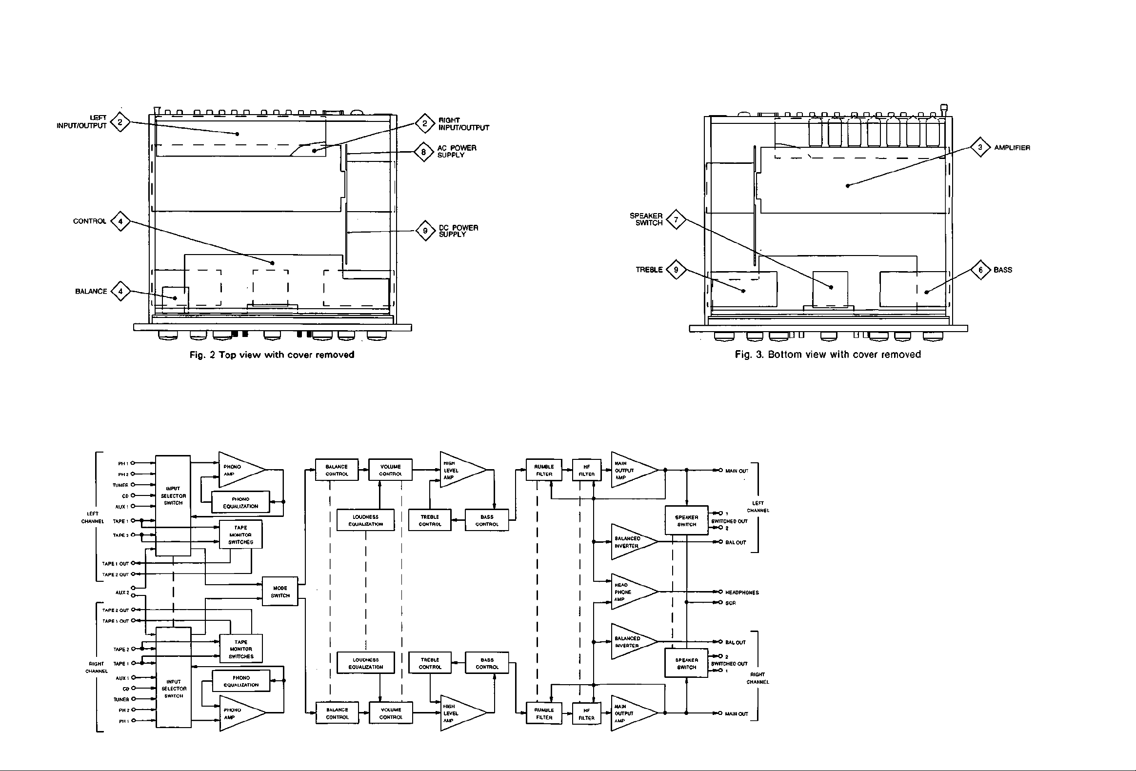
Section Locations
Block Diagram
INTERCONNECTION
PARTS LIST
Symbol Part Description
CAPACITORS
C1.C2 061276 DISC CAP, .0047uF,
JACKS
J2,J3
117563
J4,J5 117437 XLR Connector, Male
LIGHTING DEVICES
DS1.DS2 058138 Lamp Fuse Style
DS3.DS4 058137 Lamp Disc Indicator
SWITCHES
S1-S6 148068 Slide Switch (SPDT)
TRANSFORMERS
T1 159248 Power Transformer
400VAC
Phone Jack
5
6
 Loading...