

Page 1
McIntosh Laboratory, Inc. 2 Chambers Street Binghamton, New York 13903-2699 Phone: 607-723-3512 www.mcintoshlabs.com
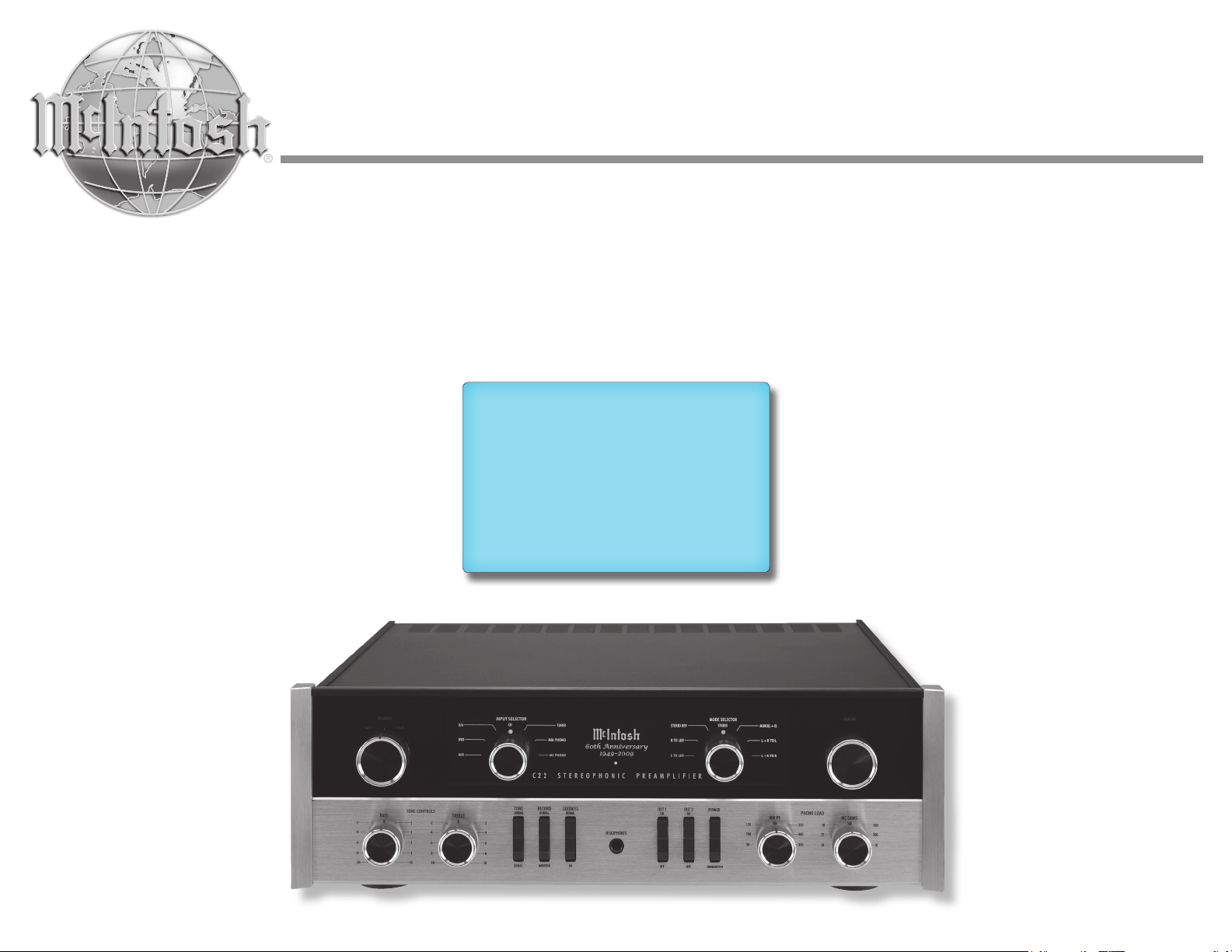
C22 60
th
Anniversary
Stereophonic Preamplier
Owner’s Manual
Page 2
The lightning ash with arrowhead, within an equilateral
triangle, is intended to alert the user to the presence of
uninsulated “dangerous voltage” within the product’s enclosure that may be of sufcient magnitude to constitute
a risk of electric shock to persons.
The exclamation point within an equilateral triangle is
intended to alert the user to the presence of important
operating and maintenance (servicing) instructions in the
literature accompanying the appliance.
WARNING - TO REDUCE RISK
OF FIRE OR ELECTRICAL
SHOCK, DO NOT EXPOSE
THIS EQUIPMENT TO RAIN OR
MOISTURE.
IMPORTANT SAFETY
INSTRUCTIONS!
PLEASE READ THEM BEFORE
OPERATING THIS EQUIPMENT.
1. Read these instructions.
2. Keep these instructions.
3. Heed all warnings.
4. Follow all instructions.
5. Do not use this apparatus near water.
6. Clean only with a dry cloth.
7. Do not block any ventilation openings. Install
in accordance with the manufacturer’s instructions.
8. Do not install near any heat sources such as
radiators, heat registers, stoves, or other appa-
ratus (including ampliers) that produce heat.
9. Do not defeat the safety purpose of the polarized or grounding-type plug. A polarized plug
has two blades with one wider than the other.
A grounding type plug has two blades and a
NO USER-SERVICEABLE PARTS
INSIDE. REFER SERVICING TO
QUALIFIED PERSONNEL.
third grounding prong. The wide blade or the
third prong are provided for your safety. If
the provided plug does not t into your outlet,
consult an electrician for replacement of the
obsolete outlet.
10. Protect the power cord from being walked on
or pinched particularly at plugs, convenience
receptacles, and the point where they exit
from the apparatus.
11. Only use attachments/accessories specied by
the manufacturer.
12. Use only with the cart, stand, tripod, bracket,
or table specied by the manufacturer, or sold with the apparatus. When a cart is used, use
caution when moving the cart/
apparatus combination to avoid
injury from tip-over.
13. Unplug this apparatus during lightning storms
or when unused for long periods of time.
14. Refer all servicing to qualied service personnel. Servicing is required when the apparatus
has been damaged in any way, such as power-
To prevent the risk of electric
shock, do not remove cover or
back. No user-serviceable parts
inside.
supply cord or plug is damaged, liquid has
been spilled or objects have fallen into the
apparatus, the apparatus has been exposed to
rain or moisture, does not operate normally, or
has been dropped.
15. Do not expose this equipment to dripping or
splashing and ensure that no objects lled
with liquids, such as vases, are placed on the
equipment.
16. To completely disconnect this equipment from
the a.c. mains, disconnect the power supply
cord plug from the a.c. receptacle.
17. The mains plug of the power supply cord shall
remain readily operable.
18. Do not expose batteries to excessive heat such
as sunshine, re or the like.
19. Connect mains power supply cord only to a
mains socket outlet with a protective earthing
connection.
2
Page 3
Thank You
Your decision to own this McIntosh C22 Stereophonic
Preamplifier ranks you at the very top among discriminating music listeners. You now have “The Best.”
The McIntosh dedication to “Quality,” is assurance
that you will receive many years of musical enjoyment
from this unit.
Please take a short time to read the information in
this manual. We want you to be as familiar as possible with all the features and functions of your new
McIntosh.
Please Take A Moment
The serial number, purchase date and McIntosh Dealer
name are important to you for possible insurance
claim or future service. The spaces below have been
provided for you to record that information:
Serial Number: _______________________________
Purchase Date: _______________________________
Dealer Name: ________________________________
Technical Assistance
If at any time you have questions about your McIntosh
product, contact your McIntosh Dealer who is familiar
with your McIntosh equipment and any other brands
that may be part of your system. If you or your Dealer
wish additional help concerning a suspected problem,
you can receive technical assistance for all McIntosh
products at:
McIntosh Laboratory, Inc.
2 Chambers Street
Binghamton, New York 13903
Phone: 607-723-1545
Fax: 607-724-0549
Customer Service
If it is determined that your McIntosh product is in
need of repair, you can return it to your Dealer. You
can also return it to the McIntosh Laboratory Service
Department. For assistance on factory repair return
procedure, contact the McIntosh Service Department
at:
McIntosh Laboratory, Inc.
2 Chambers Street
Binghamton, New York 13903
Phone: 607-723-3515
Fax: 607-723-1917
Table of Contents
Safety Instructions ..................................................... 2
Thank You and Please Take a Moment ...................... 3
Technical Assistance and Customer Service ............. 3
Table of Contents ....................................................... 3
General Information .................................................. 3
Connector and Cable Information .............................4
Introduction ................................................................ 4
Performance Features ................................................ 4
Dimensions ................................................................5
Installation .................................................................6
Rear Panel Connections ............................................. 7
How to Connect the C22 ............................................ 8
Connection Diagrams (Separate Sheets).... Mc1A and
Mc1B
How to use the Remote Control ................................. 9
Front Panel Displays, Controls, Switches
and Jack .................................................................... 10
How to Operate the C22 .......................................... 11
Specifications ........................................................... 14
Packing Instruction .................................................. 15
Copyright 2009 © by McIntosh Laboratory, Inc.
General Information
1. The C22 uses Vacuum Tubes for amplifying the
audio signal. The C22 is designed to have only
qualified Service Personnel perform any part(s)
replacement including all the vacuum tubes.
2. For additional connection information, refer to the
owner’s manual(s) for any component(s) connected
to the C22 Stereophonic Preamplifier.
3. The Main AC Power going to the C22 and any
other McIntosh Component(s) should not be applied
until all the system components are connected
together. Failure to do so could result in malfunctioning of some or all of the system’s normal operations. When the C22 and other McIntosh Components are in their Standby Power Off Mode, the
Microprocessor’s Circuitry inside each component
is active and communication is occurring between
them.
4. Up to two Sensors can be wired in parallel for Remote Control of the C22 from other rooms.
5. Balanced and Unbalanced Inputs and Outputs can
be mixed. For example, you may connect signal
sources to Unbalanced Inputs and send signals
from the Balanced Outputs. You can also use Balanced and Unbalanced Outputs simultaneously,
connected to different Power Amplifiers.
6. When discarding the unit, comply with local rules
or regulations. Batteries should never be
thrown away or incinerated but disposed
of in accordance with the local regulations
concerning battery disposal.
7. For additional information on the C22 and
other McIntosh Products please visit the
McIntosh Web Site at www.mcintoshlabs.
com.
3
Page 4
General Information, Cable Information, Introduction and Performance Features
PIN 2 PIN 1
PIN 3
PIN 1
PIN 2
PIN 3
Power
Control
Ground
N/C
Data
Signal
N/C
Data
Ground
Connector and Cable Information
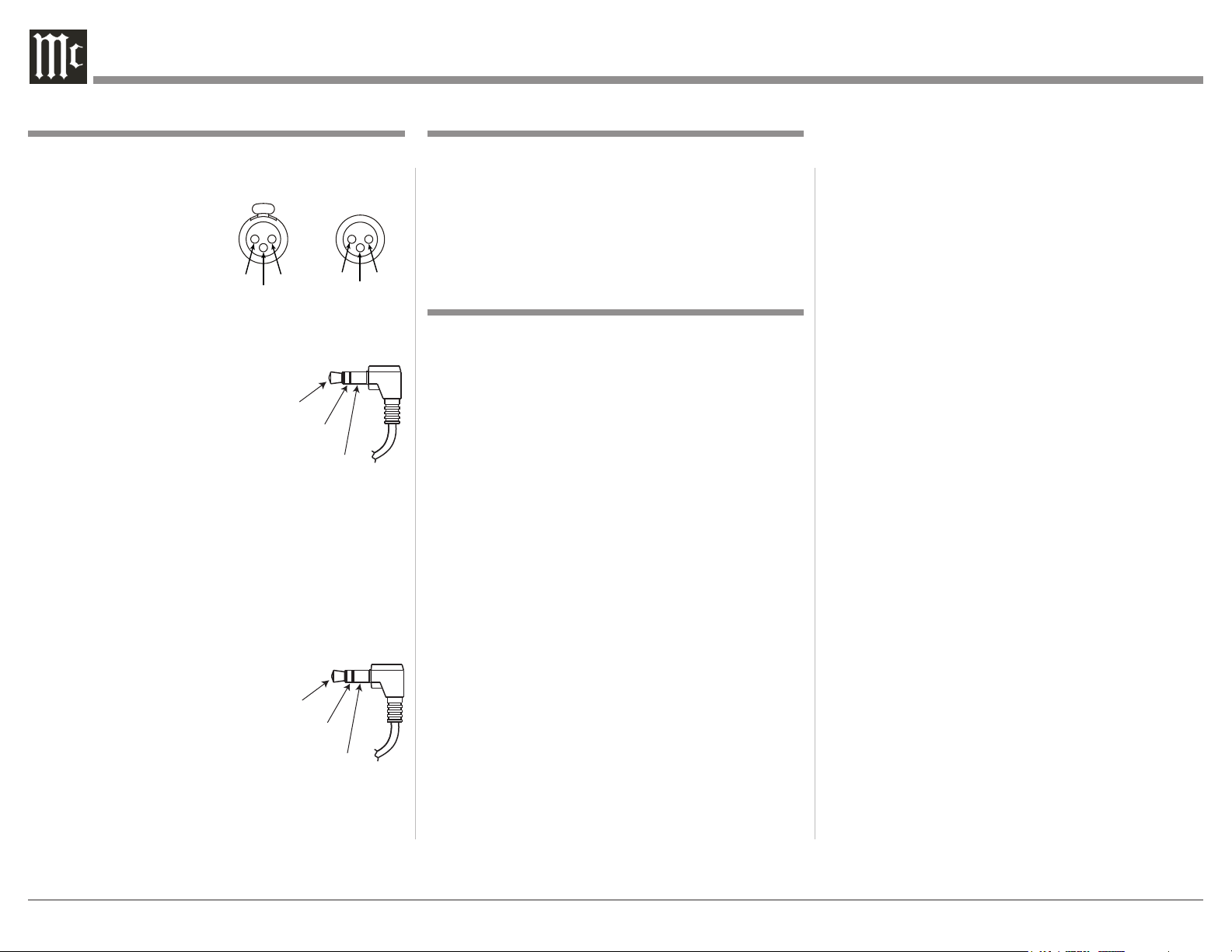
XLR Connectors
Below is the Pin configuration for the XLR Balanced
Input and Output Connectors on the C22. Refer to the
diagrams for connections:
PIN 1: Shield/Ground
PIN 2: + Signal
PIN 3: - Signal
Power Control Connectors
The C22 Power Control Output Jacks send Power On/
Off Signals when connected to
McIntosh Components. A 1/8
inch stereo mini phone plug
is used for connection to the
Power Control Outputs on the
C22.
Note: The Data, Power Control Connecting Cable is
available from the McIntosh Parts Department:
Data and Power Control Cable Part No. 170-202
Six foot, shielded 2 conductor, with 1/8 inch stereo
mini phone plugs on each end.
Data Port Connectors
The C22 Data Out Ports send Remote Control Signals
to McIntosh Source Components.
A 1/8 inch stereo mini phone plug
is used for connection.
4
Introduction
The McIntosh C22 Stereophonic Preamplifier is one
of the finest Tube Preamplifiers ever created. The
versatile Preamplifier provides connections for various input sources and outputs to drive multiple Power
Amplifiers. The C22 reproduction is sonically transparent and absolutely accurate. The McIntosh Sound is
“The Sound of the Music Itself.”
Performance Features
• Electromagentic Input Switching
Digital Logic integrated circuits drive Electromagnetic Switches on all Inputs and operating functions
for reliable, noiseless, distortion free switching. There
is also a Record Monitor function for checking the
progress of a recording.
• Moving Coil and Moving Magnet Phono Inputs
The C22 contains two different precision Phono Preamplifier Circuits. One for low output Moving Coil
Phono Cartridges with selectable resistance loading,
the other is for Moving Magnet Cartridges with selectable capacitive loading. Both circuits use the latest designs to provide the lowest possible noise and distortion. The RIAA Equalization Circuitry utilizies close
tolerance resistors and capacitors for an extremely flat
frequency response.
• Balanced Inputs
The Balanced Inputs allow the connection of a source
component using long cable lengths without a loss in
sound quality.
• Low Distortion
Distortion levels of all types are less than 0.08%. Music is amplified with total transparency and accuracy.
• Tone Controls with Bypass
The C22 allows for bypassing the Bass and Treble
Tone Circuitry.
• Output Switching
Front panel Output Push-buttons control two Switched
Outputs that allow sending signals to two separate
Power Amplifiers.
• Remote Control with External Sensor Input
The Remote Control provides basic control of the C22
operating functions and any McIntosh Source Components connected to it. Enjoy your McIntosh System
from another room in your home by connecting external sensors.
• Power Control Output
A Power Control connection for convenient Turn-On
of McIntosh Power Amplifiers, Source Components
and Accessories is included.
• Precision Parts
Only the finest precision 1% tolerance resistors are
used throughout.
• Special Power Supply
Fully regulated Power Supplies and a special R-Core
Power Transformer ensure stable noise free operation
even though the power line varies.
• Extruded Side Panels
The sides of the C22 are extruded aluminum panels
with a bead blast textured surface and a black anodized finish.
• Solid State Front Panel Illumination
The Illumination of the Front Panel is accomplished
by extra long life Light Emitting Diodes (LEDs).
Page 5
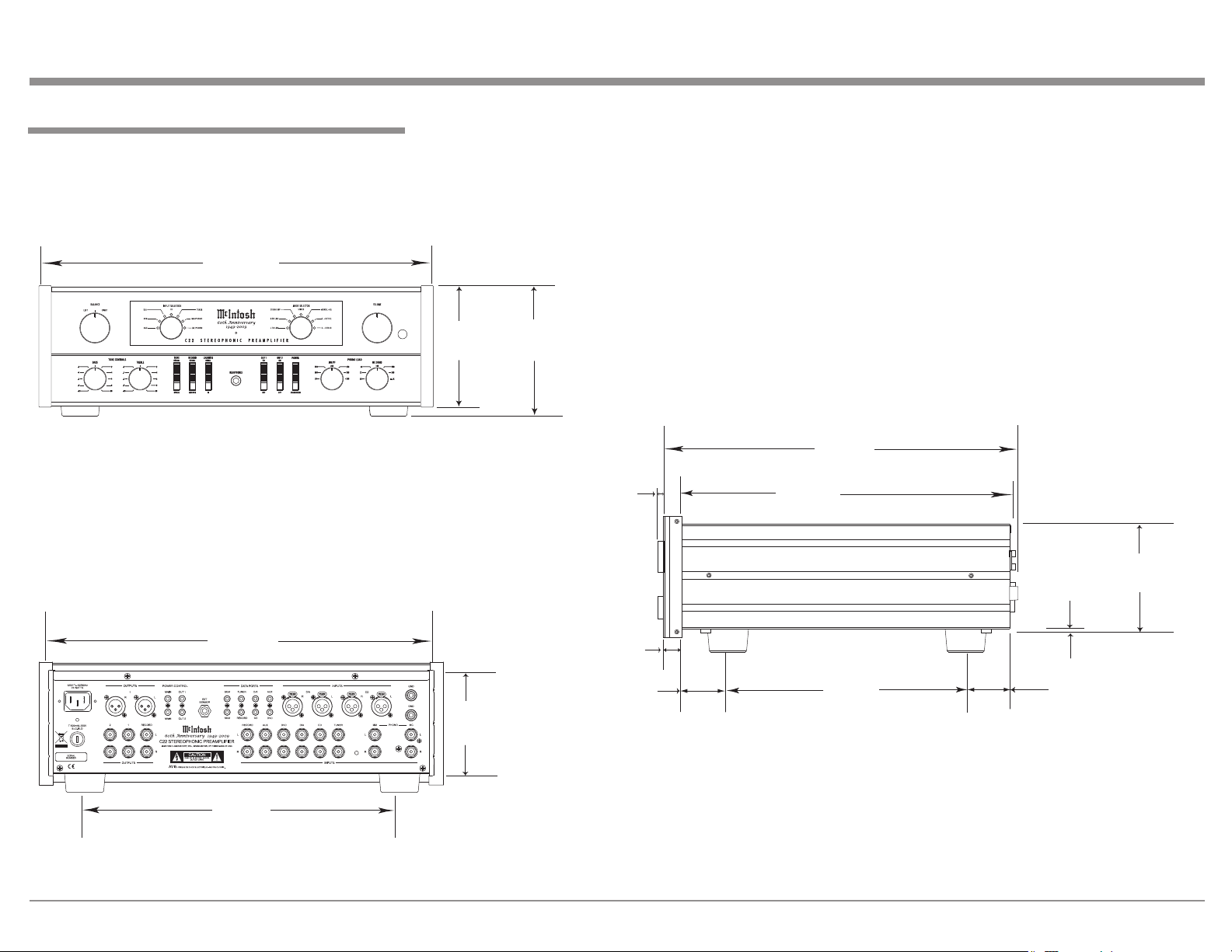
Dimensions
Side View of the C22
Front View of the C22
Rear View of the C22
17-1/2"
44.45cm
6"
15.24cm
5-3/8"
13.69cm
4-5/8"
11.75cm
13-1/4"
33.65cm
17"
43.18cm
14-1/2"
36.83cm
15-7/8"
40.32cm
3/16"
0.48cm
4-13/16"
12.22cm
10-1/2"
26.67cm
5/8"
1.59cm
13/16"
2.06cm
2"
5.08cm
1-15/16"
4.92cm
The following dimensions can assist in determining
the best location for your C22.
Dimensions
5
Page 6

Installation
8-5/8"
21.91cm
15-1/2"
39.37cm
15-1/16"
38.26cm
1"
2.54cm
Cutout Opening
for Ventilation
Cutout Opening for Ventilation
Support
Shelf
Chassis
Spacers
C22 Side View
in Custom Cabinet
C22 Bottom View
in Custom Cabinet
1-1/16"
2.70cm
12-5/16"
31.27cm
3"
7.62cm
Note: Center the cutout Horizontally on the unit.
For purposes of clarity, the above
illustration is not drawn to scale.
Cabinet
Front
Panel
Opening
for Ventilation
C22 Front Panel
Custom Cabinet Cutout
10-7/8"
27.62cm
17-1/16"
43.34cm
Cutout Opening for Custom Mounting
Cabinet Front Panel
6"
15.24cm
Opening for Ventilation
The C22 can be placed upright on a table or shelf,
standing on its four feet. It also can be custom installed in a piece of furniture or cabinet of your
choice. The four feet may be removed from the bottom
of the C22 when it is custom installed as outlined below. The four feet together with the mounting screws
should be retained for possible future use if the C22
is removed from the custom installation and used free
standing. The required panel cutout, ventilation cutout
and unit dimensions are shown.
Always provide adequate ventilation for your C22.
Cool operation ensures the longest possible operating
life for any electronic instrument. Do not install the
C22 directly above a heat generating component such
as a high powered amplifier. If all the components are
installed in a single cabinet, a quiet running ventilation fan can be a definite asset in maintaining all the
system components at the coolest possible operating
temperature.
A custom cabinet installation should provide the following minimum spacing dimensions for cool operation.
Allow at least 6 inches (15.24cm) above the top, 2
inches (5.08cm) below the bottom and 1 inch (2.54cm)
on each side of the Tube Preamplifier, so that airflow
is not obstructed. Allow 19-1/2 inches (49.53cm) depth
behind the front panel. Allow 1-1/8 inch (2.9cm) in
front of the mounting panel for knob clearance. Be
sure to cut out a ventilation hole in the mounting shelf
according to the dimensions in the drawing.
Installation
6
Page 7
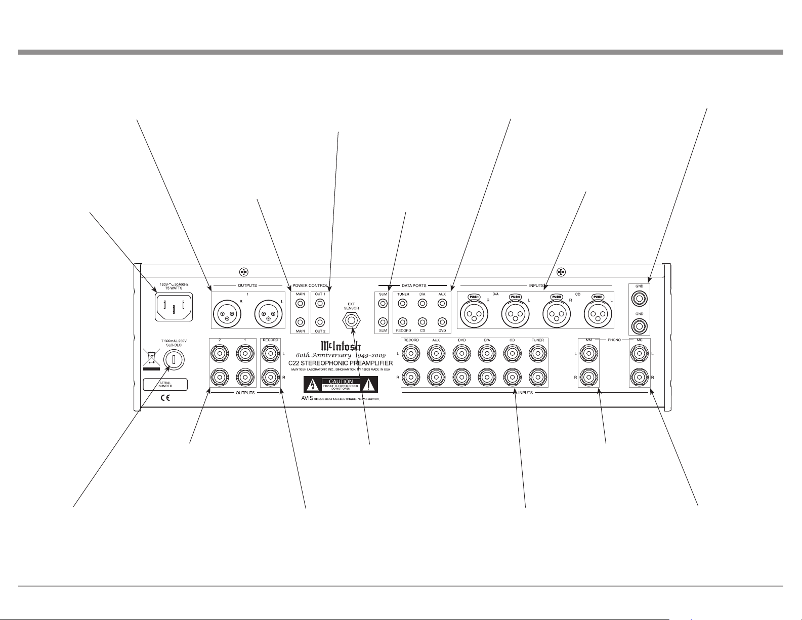
Rear Panel Connections
OUTPUTS 1 (Balanced) send
signals to a Power Amplifier
and is controlled by the C22
Front Panel OUT 1 Switch
Connect the C22 power cord
to a live AC outlet. Refer
to information on the back
panel of your C22 to determine the correct voltage for
your unit
OUTput 1 and OUTput 2 send
Turn-On signals to McIntosh
components and are controlled
by the C22 Front Panel OUT 1
and OUT 2 Switches
MAIN POWER CONTROL
Output sends a turn-on
signal to a McIntosh Component when the C22 is
turned on
SUM DATA PORT
sends data signals
from all the Data
Ports to McIntosh
Components for
control
DATA PORTS send signals to
McIntosh Source Components
to allow control with the C22
Remote Control
D/A and CD INPUTS
(Balanced) accept high
level program source
signals
GND terminals accept
a ground wire from a
turntable
Main Fuse holder, refer
to information on the
back panel of your C22 to
determine the correct fuse
size and rating
OUTPUTS 1 and 2 send
signals to Power Amplifiers and are switched On/
Off with the Front Panel
OUT 1 and 2 Switches
RECORD OUT
sends signals to
the input of a
recording device
EXT SENSOR connector
permits the connection of
a McIntosh IR Sensor for
remote operation
PHONO MM accepts
signals from a Moving
Magnet phono cartridge
RECORD, AUX, DVD, D/A,
CD, and TUNER, INPUTS
accept high level program
source signals
PHONO MC accepts
signals from a Moving
Coil phono cartridge
7
Page 8

How to Connect the C22
The C22 has the ability to automatically switch power
On/Off to McIntosh Source Components via the
Power Control connections. The Data Port Connections allow for the remote operation of basic functions
using the C22 Remote Control. With an external sensor connected to the C22, remote control operation of
the system is possible from another room and/or when
the C22 is located in a cabinet with the doors closed.
The connection instructions below, together with
the C22 Input and Output Connection Diagrams located on the separate folded sheet “Mc1A/1B”, are an
example of a typical audio system. Your system may
vary from this, however the actual components would
be connected in a similar manner. For additional information refer to “Connector and Cable Information”
on page 4.
Power Control Connections:
1. Connect a Control Cable from the C22 POWER
CONTROL MAIN (lower) Jack to the Power Control In on the AM/FM Tuner.
3. Connect a Control Cable from the AM/FM Tuner
Power Control Out Jack to the SACD/CD Player
Power Control In Jack.
4. Connect a Control Cable from the SACD/CD
Player Power Control Out Jack to the Turntable
Power Control Remote In Jack.
5. Connect a Control Cable from the Turntable Power
Control Remote Out Jack to the Music Server
Power (PWR) Control (CTRL) In Jack.
6. Connect a Control Cable from the C22 POWER
CONTROL MAIN (upper Jack) to the Power
Amplifier (right) Power Control In Jack. Connect
a Control Cable from the Power Amplifier (right)
Power Control Out Jack to the Power Amplifier
(left) Power Control In Jack.
7. Optionally connect a Control Cable from the C22
POWER CONTROL OUT 2 Jack to the Stereo
Power Amplifier (Secondary Room) Power Control In Jack.
8. Connect any additional McIntosh Components in a
similar manner, as outlined in steps 1 thru 4.
Data Control Connections:
9. Connect a Control Cable from the C22 TUNER
DATA PORTS Jack to the AM/FM Tuner Data In
Tuner 1 Jack.
10. Connect a Control Cable from the C22 CD DATA
PORT Jack to the SACD/CD Player Data In Jack.
11. Connect a Control Cable from the C22 RECORD
DATA PORT Jack to the Music Server Data In
Jack.
12. Connect any additional McIntosh Components in a
similar manner, as outlined in steps 9 thru 11.
Sensor Connections:
13. Connect a RG59U or RG6U Cable from the C22
EXT (external) SENSOR “F” Connector to the
Sensor “F” Connector.
Audio Connections:
14. Connect an Audio Cable from the C22 TUNER
INPUT Jacks to the AM/FM Tuner, Tuner 1 Fixed
Output Jacks.
15. Connect Balanced Cables from the C22 CD INPUT Jacks to the SACD/CD Player Fixed Balanced
Output Jacks.
Note: Unbalanced Audio Cables may be used instead
of the Balanced Cables, but not both.
16. Connect an Audio Cable from the C22 RECORD
INPUT Jacks to the Music Server Output Jacks.
17. Connect an Audio Cable from the C22 RECORD
OUTPUT Jacks to the Music Server Input 3 Jacks.
18. Connect the Audio Cables coming from the Turn-
How to Connect the C22
table to the C22 MC PHONO INPUT Jacks.
Note: If the Turntable has a Moving Magnet Car-
tridge, connect the audio cables to the C22
MM PHONO INPUT instead of the MC Input.
19. Connect Balanced Cables from the C22 OUTPUTS
1 L and R Jacks to the Power Amplifiers (Main
Left and Right) Balanced Input Jacks.
20. Optionally, connect an Audio Cable from the C22
OUTPUT 2 Jacks to the McIntosh Power Ampli-
fier (Secondary) Input Jacks.
21. Connect any additional McIntosh Components in a
similar manner, as outlined in steps 14 thru 20.
Ground Connections:
22. Connect the Ground Cable coming from the Turntable to the C22 GND Binding Post.
AC Power Cords Connections:
23. Connect the C22 AC Power Cord to a live AC
outlet as illustrated.
8
Page 9
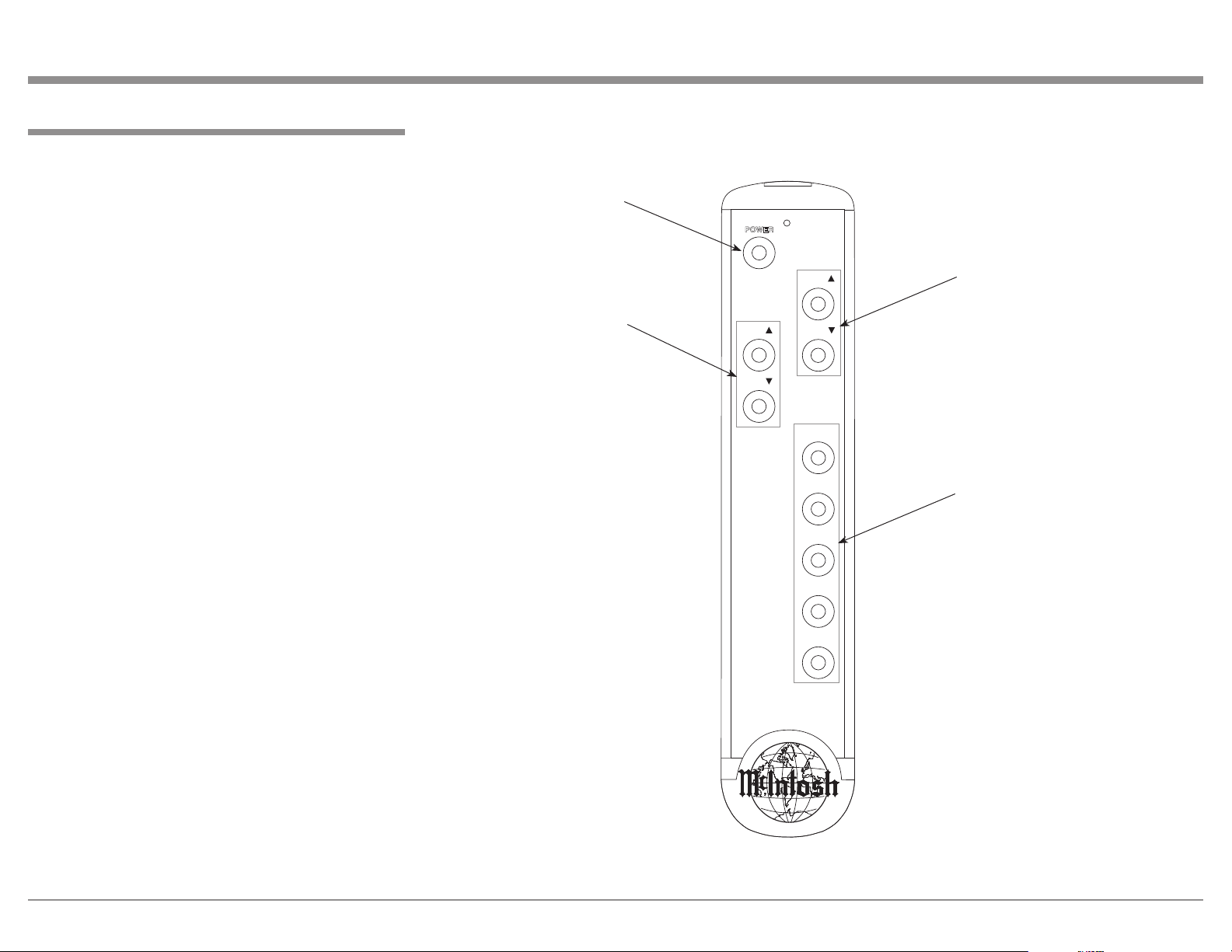
How to use the Remote Control
POWER
INPUT
PLAY
STOP
NEXT
BACK
PAUSE
VOL
VOL
INPUT
The supplied Remote Control is capable of directly
controlling the functions of contemporary McIntosh
Source Components connected to the C22 Tube Preamplifier.
How to use the Remote Control
Press to Power the
C22 ON or OFF
Power
To Switch the C22 ON or OFF press the POWER
Push-button on the Remote Control.
Note: During the Tube Warm Up time (when first
switched ON), the Front Panel INPUT and MODE
SELECTOR LEDs will flash and the Audio Outputs
will be muted.
Input Source Selection
Press the INPUT Upp or Downq Push-button to
select the desired program source.
Disc, Server and Tape Functions
Use the PLAY, STOP, NEXT, BACK and PAUSE
Push-buttons to operate a DVD Player, CD Player, CD
Changer, Music Server or Tape Recorder.
Notes: 1. For Remote Control Operation of a Source
Component using the C22 Remote Control, a
connection is required between the appropriate C22 Data Port and the Source Component
Data Port. Refer to pages 4 and 8 for additional
information.
2. Refer to the Source Component’s Owner’s
Manual for specific operating information.
Scrolls through the
available C22 Inputs
Adjusts the volume
level up or down
Selects Disc Player,
Music Server or Tape
Recorder Functions and
also performs various
functions on a variety of
McIntosh Components
Volume
Press the Upp or Downq VOLUME Push-button to
raise or lower the listening volume level.
Note: The Record Signals present at RECORDER OUT-
PUTS are not affected by volume changes.
9
Page 10

Front Panel Displays, Controls, Switches and Jack
BALANCE Control
allows the adjustment
of the relative volume
balance between channels
Indicates when the
C22 is connected to
an active AC Outlet
INPUT SELECTOR Control
selects the desired audio signals
for listening and recording
MODE SELECTOR allows
for listening to various
channel combinations from
Stereo to Mono
VOLUME Control
adjusts the listening level
for both channels
IR Sensor receives
commands from a
Remote Control
BASS Control provides 10dB boost
or cut with a center
flat position
10
TREBLE Control
provides 10dB
boost or cut with a
center flat position
TONE BYPASS when
activated the audio
signal bypasses the Tone
Controls
REC MONITOR
allows listening
to the playback of
RECORD Source
while the recording
is in process
LOUDNESS switch provides frequency
response contoured to compensate
for the sensitivity of the human ear at
softer listening levels
Connection for low
impedance dynamic
headphones with 1/4”
(6.3mm) stereo phone
type plug, for private
listening
POWER Switch,
switches the C22
ON or STAND/
BY(Off )
OUTPUTS 1 and 2 switches allow
the C22 to switch Power Control
and Audio to two separate Power
Amplifiers
PHONO LOAD MC OHMS
provides seven different
resistive loads for a Moving
Coil Phono Cartridge
PHONO LOAD MM PF provides
seven different capacitive loads
for a Moving Magnet Phono
Cartridge
Page 11

How to Operate
POWER
INPUT
PLAY
STOP
NEXT
BACK
PAUSE
VOL
VOL
INPUT
How to Operate
Power On
The Red LED located under the “1949-2009” nomenclature on the Front Panel lights to indicate the C22 is
connected to an active AC Outlet. To Switch ON the
C22, momentarily press downward the POWER Rocker Switch on the Front Panel or the POWER Pushbutton on the Remote Control. During the Tube Warm
Up time (when first switched ON), the Front Panel
INPUT and MODE SELECTOR LEDs will flash and
the Audio Outputs will be muted. Refer to illustration
on the previous page and figure 1 on this page.
Source Selection
Select the desired source using the INPUT SELECTOR Control on the Front Panel or press the INPUT
▲ or ▼ on the Remote Control.
Volume Control
Rotate the Front Panel VOLUME Control or use the
VOLume ▲ (Up) or ▼ (Down) Push-buttons on the
Remote Control for the desired listening level.
Loudness Compensation
To activate the Loudness Compensation Circuitry
place the LOUDNESS Rocker Switch in the IN Position on the Front Panel. When active, the Loudness
Compensation Circuitry works in conjunction with the
rotational position of the Volume Control. It compensates for the sensitivity of the human ear at softer
listening levels by boosting the volume level of the
low frequencies relative to the midrange frequencies
to provide a fuller sound.
Balance Control
Rotate the Front Panel BALANCE Control as needed
to achieve approximately equal listening volume levels
in each Loudspeaker. Rotate the BALANCE counterclockwise to emphasize the Left Channel by reducing
the level of the Right Channel. Rotate the BALANCE
clockwise to emphasize the Right Channel by reducing the level of the Left Channel.
Mode Selector
The Front Panel MODE SELECTOR Control allows
the Left and Right Input Signals from the desired
source to be combined into various different outputs
sent to the Loudspeakers and Headphones. Refer to
the chart below:
Output Channels
Mode
Selection
STEREO
STEREO
REV
MONO
L to L&R
R to L&R
L+R to L
L+R to R
Left + Right Input Signals Left + Right Input Signals
Left +Right Input Signals -
Bass Control
Rotate the BASS clockwise from the center (12
o’clock) position to emphasize the low frequency content of the music. Likewise rotate the BASS counterclockwise from the center position to de-emphasize
the low frequency content of the music.
Treble Control
Rotate the TREBLE clockwise from the center (12
o’clock) position to emphasize the high frequency
content of the music. Likewise rotate the TREBLE
counterclockwise from the center position to de-em-
LEFT RIGHT
Left Input Signal Right Input Signal
Right Input Signal Left Input Signal
Left Input Signal Left Input Signal
Right Input Signal Right Input Signal
- Left+ Right Input Signals
phasize the high frequency content
of the music.
Tone Bypass Switch
When the TONE Switch on the
Front Panel is placed in the BYPASS
position the Tone Controls together
with the Tone Circuitry is totally
bypassed for a flat response.
Record Monitor
To activate the Record Monitor
Circuit place the RECORD Rocker
Switch in the MONITOR Position
on the Front Panel. When active, the
sound coming from Record Source
Component will be heard. Some
Recording Components allow for
listening to the Playback Signal a
fraction of a second after the recording has taken place.
Output 1 and 2
To switch Off the audio signal going
to the Power Amplifiers connected
to the C22 Preamplifier Outputs,
place the OUTput 1 and/or the
OUTput 2 Rocker Switch in the OFF
Figure 1
Position on the Front Panel. When there is a Power
Control Connection between the C22 Power Control
OUT 1 or OUT 2 and the Power Amplifier(s), the
Power Amplifier(s) will be switched Off.
Phono Load Adjustments
There are Phono Load Adjustments for both types of
Phono Cartridges, Moving Coil (MC) and Moving
11
Page 12

How to Operate, con’t
POWER
INPUT
PLAY
STOP
NEXT
BACK
PAUSE
VOL
VOL
INPUT
Magnet (MM). The resistive load for the MC Input
is selectable from 10 ohms to 1,000 ohms. The capacitive load for the MM Input is selectable from 50
picofarads to 350 picofarads.
Select the Phono Load setting using the Front Panel
MC or MM Control for the cartridge type connected
to the C22. Choose the value closest to the recommended load value specified by the Phono Cartridge
Manufacturer.
Headphones Jack
Connect a pair of dynamic headphones with a 1/4”
(6.3mm) stereo phone type plug to the Headphones
Jack for private listening.
How To Make A Recording
1. Use the Input Selector to choose the desired Source
Input Signal you wish to record. Refer to figure 2.
2. Adjust the record level using the recorder volume
control and proceed with the recording process.
How to Operate, con’t
3. To listen to the playback of the program source just
recorded, place the RECORD switch on the front
panel to the MONITOR position. The Front Panel
INPUT SELECTOR LED will flash indicating the
Input Source selected for recording. During the
time the RECORD Switch is in the MONITOR position Source Selection is not possible, either by using the Front Panel INPUT SELECTOR or Remote
Control INPUT Upp or Downq push-buttons.
Refer to figures 2 and 3.
Note: The C22 RECORD OUTPUT Signals are not
affected by the setting of VOLUME or BALANCE
Controls.
Reset of Microprocessors
In the unlikely event the controls of the C22 stop functioning, the microprocessors can be reset by placing
the Front Panel POWER Switch in the STANDBY/ON
position and holding it in for fifteen seconds and then
releasing the switch.
12
Figure 3
Figure 2
Page 13

Notes
13
Page 14

Specications
Specications
Frequency Response
+0, -0.5dB from 20Hz to 20,000Hz
+0, -1dB from 10Hz to 100,000Hz
Total Harmonic Distortion
0.08% from 20Hz to 20,000Hz
Rated Output (Output 1 and 2)
2.5V Unbalanced, 5V Balanced
Maximum Voltage Output
8V RMS Unbalanced, 16V RMS Balanced
Sensitivity (for rated output)
High Level, 450mV unbalanced, 900mV balanced
Phono MM, 4.5mV
Phono MC, 0.45mV
Signal To Noise Ratio (A-Weighted)
High Level, 98dB
Phono, 80dB
Input Impedance
High Level, 20K ohms unbalanced, 20k ohms balanced
Phono MM, 47K ohms; 50 to 350pF, in 50pF steps
Phono MC, 10, 25, 50, 100, 200, 500 or 1,000 ohms;
100pF
Voltage Gain
High Level to Record Output: 0dB
High Level to Output 1 and 2: 15dB
Phono MM to Record Output: 40dB
Phono MC to Record Output: 60dB
Output Impedance
220 ohms
Headphone Load Impedance
16 ohms to 250 ohms
Tube Compliment
High Level Circuitry: 2 - 12AX7A
MM Phono Circuitry: 2 - 12AX7A
MC Phono Circuitry: 2 - 12AX7A
Power Requirements
100V ~ 50/60Hz at 75 watts
110V ~ 50/60Hz at 75 watts
120V ~ 50/60Hz at 75 watts
220V ~ 50/60Hz at 75 watts
230V ~ 50/60Hz at 75 watts
240V ~ 50/60Hz at 75 watts
Standby, less than 2 watts
Note: Refer to the rear panel of the C22 for the correct
voltage.
Overall Dimensions
Width is 17-1/2 inches (44.45cm)
Height is 6 inches (15.24cm) including feet
Depth is 18 inches (45.72cm) including the Front
Panel, Knobs and Cables
Weig ht
27 pounds (12.25 kg) net, 43.4 pounds (19.68 kg) in
shipping carton
Shipping Carton Dimensions
Width is 26-1/2 inches (67.3cm)
Depth is 24-1/4 inches (61.6cm)
Height is 11-3/4 inches (29.9cm)
Maximum Input Signal
High Level, 5V Unbalanced, 10V Balanced
Phono MM, 50mV
Phono MC, 5mV
14
Page 15
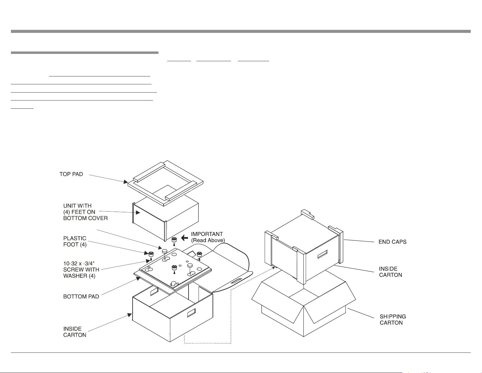
Packing Instructions
FOAM PLUG
In the event it is necessary to repack the equipment for
shipment, the equipment must be packed exactly as
shown below. It is very important that the four plastic feet are attached to the bottom of the equipment.
This will ensure the proper equipment location on the
bottom pad. Failure to do this will result in shipping
damage.
Use the original shipping carton and interior parts
only if they are all in good serviceable condition. If
a shipping carton or any of the interior part(s) are
needed, please call or write Customer Service Department of McIntosh Laboratory. Refer to page 4. Please
see the Part List for the correct part numbers.
Packing Instructions
Quantity Part Number Description
1 033838 Shipping carton only
4 033837 End cap
1 033836 Inside carton only
1 033725 Top pad
1 034301 Bottom pad
2 034446 Foam plug
4 017937 Plastic foot
4 400159 #10-32 x 3/4” screw
4 404080 #10 Flat washer
15
Page 16

McIntosh Laboratory, Inc.
2 Chambers Street
Binghamton, NY 13903
www.mcintoshlabs.com
The continuous improvement of its products is the
policy of McIntosh Laboratory Incorporated who
reserve the right to improve design without notice.
Printed in the U.S.A.
McIntosh Part No. 04112100
 Loading...