

Page 1
3A
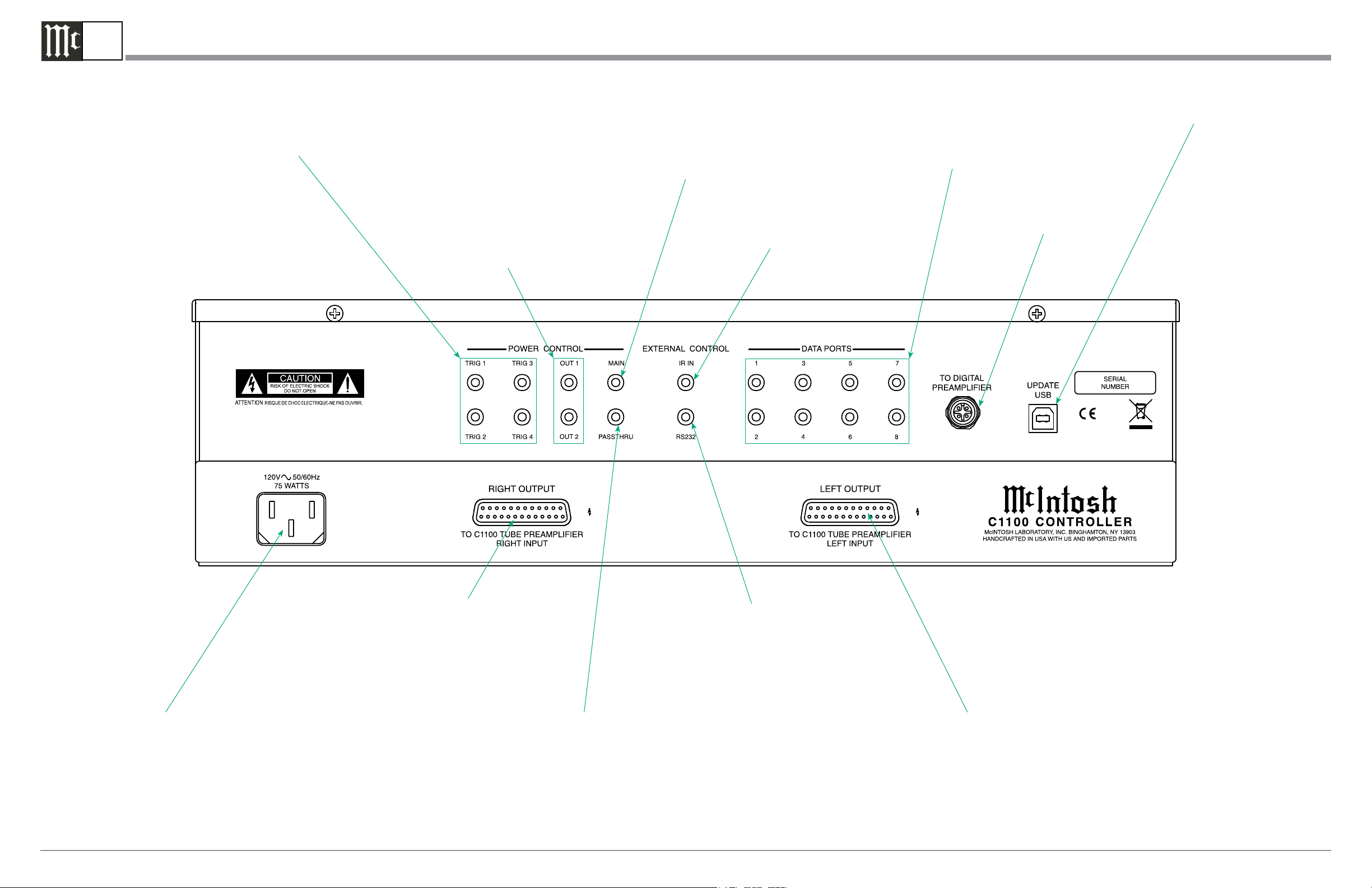
C1100C Rear Panel Connections
POWER CONTROL TRIGger outputs 1 thru 4 are assignable to send
turn On/Off signals to components
POWER CONTROL OUT
1 and 2 send turn On/Off
signals to a McIntosh Component when Output 1 and 2
are activated
POWER CONTROL MAIN
Output sends turn On/
Off signals to a McIntosh
Component when the C1100
is switched On/Off
IR INput for signals from
a compatible IR Sensor for
Remote Control use
DATA PORTS are assignable
to send signals to Source
Components to allow control
with the C1100 Remote Control
For use with a future
McIntosh Model
For Service Use Only
RIGHT OUTPUT Connector accepts the
custom McIntosh 23-Conductor Cable. This
cable connects to the C1100 RIGHT TUBE
PREAMPLIFIER INPUT. It supplies the
control signals and power supply voltages
for the Right Channel Circuitry in the
Preamplifier
Connect the C1100 power cord to a live
AC outlet. Refer to information on the
back panel of your C1100 to determine
the correct voltage for your unit
McIntosh Laboratory, Inc. 2 Chambers Street Binghamton, New York 13903-2699 Phone: 607-723-3512 FAX: 607-724-0549 Part No. 04164600
PASSTHRU Power Control
Input receives turn On/
Off signals from an Audio/
Video Processor
RS232 connector
for connection to a
computer or other
control device
LEFT OUTPUT Connector accepts the
custom McIntosh 23-Conductor Cable. This
cable connects to the C1100 LEFT TUBE
PREAMPLIFIER INPUT. It supplies the
control signals and power supply voltages for the Left Channel Circuitry in the
Preamplifier
Page 2
3B
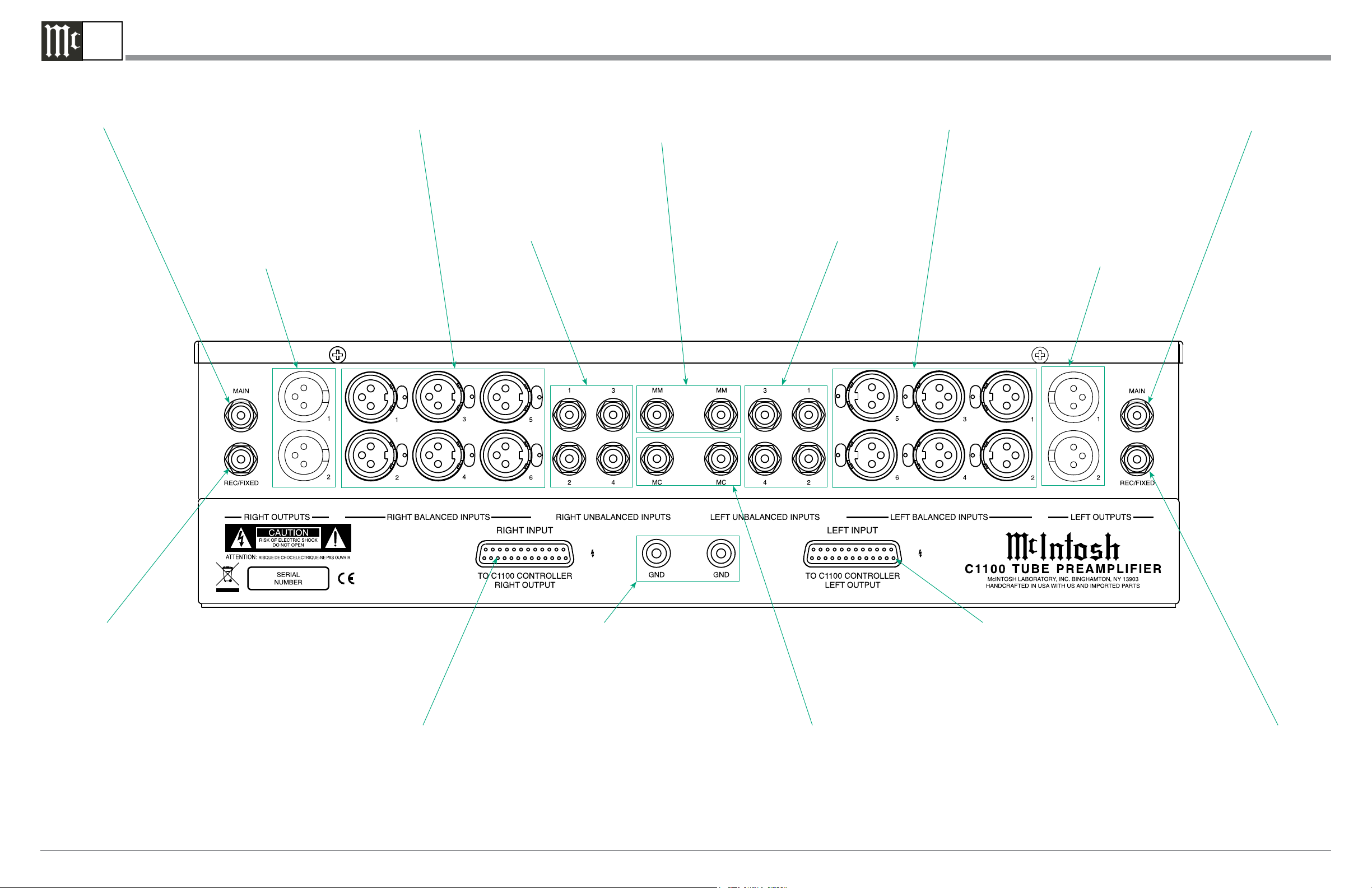
C1100T Rear Panel Connections
RIGHT OUTPUT MAIN
(Unbalanced) sends signals to a Power Amplifier
RIGHT OUTPUT 1 and 2 Balanced send signals to Power
Amplifier(s) and are switched On/
Off using a trim setting with the
Front Panel Controls or Remote
Control Push-Buttons
RIGHT BALANCED INPUTS
1 thru 6 accept high level
program source signals
RIGHT UNBALANCED
INPUTS 1 thru 4 accept high level program
source signals
MM (Right and Left
channels) accept signals
from a Moving Magnet
Phono Cartridge
LEFT UNBALANCED
INPUTS 1 thru 4 accept high level program
source signals
LEFT BALANCED INPUTS
1 thru 6 accept high level program source signals
LEFT OUTPUT 1 and 2 Balanced send signals to Power
Amplifier(s) and are switched
On/Off using a trim setting
with the Front Panel Controls or
Remote Control Push-Buttons
LEFT OUTPUT MAIN (Unbalanced) sends signals to a
Power Amplifier
RIGHT OUTPUT
REC/FIXED sends
signals to the input
of a recording device
RIGHT INPUT Connector accepts the custom
McIntosh 23-Conductor Cable. This cable connects to the C1100 CONTROLLER OUTPUT.
It supplies the control signals and power supply voltages for the Right Channel Circuitry in
the Preamplifier
McIntosh Laboratory, Inc. 2 Chambers Street Binghamton, New York 13903-2699 Phone: 607-723-3512 FAX: 607-724-0549
GND terminals accept
a ground wire from a
turntable
MC (Right and Left channels)
accepts signals from a Moving
Coil Phono Cartridge
LEFT INPUT Connector accepts the custom
McIntosh 23-Conductor Cable. This cable connects to the C1100 CONTROLLER OUTPUT.
It supplies the control signals and power supply voltages for the Left Channel Circuitry in
the Preamplifier
LEFT OUTPUT
REC/FIXED sends
signals to the input
of a recording device
 Loading...