

Page 1
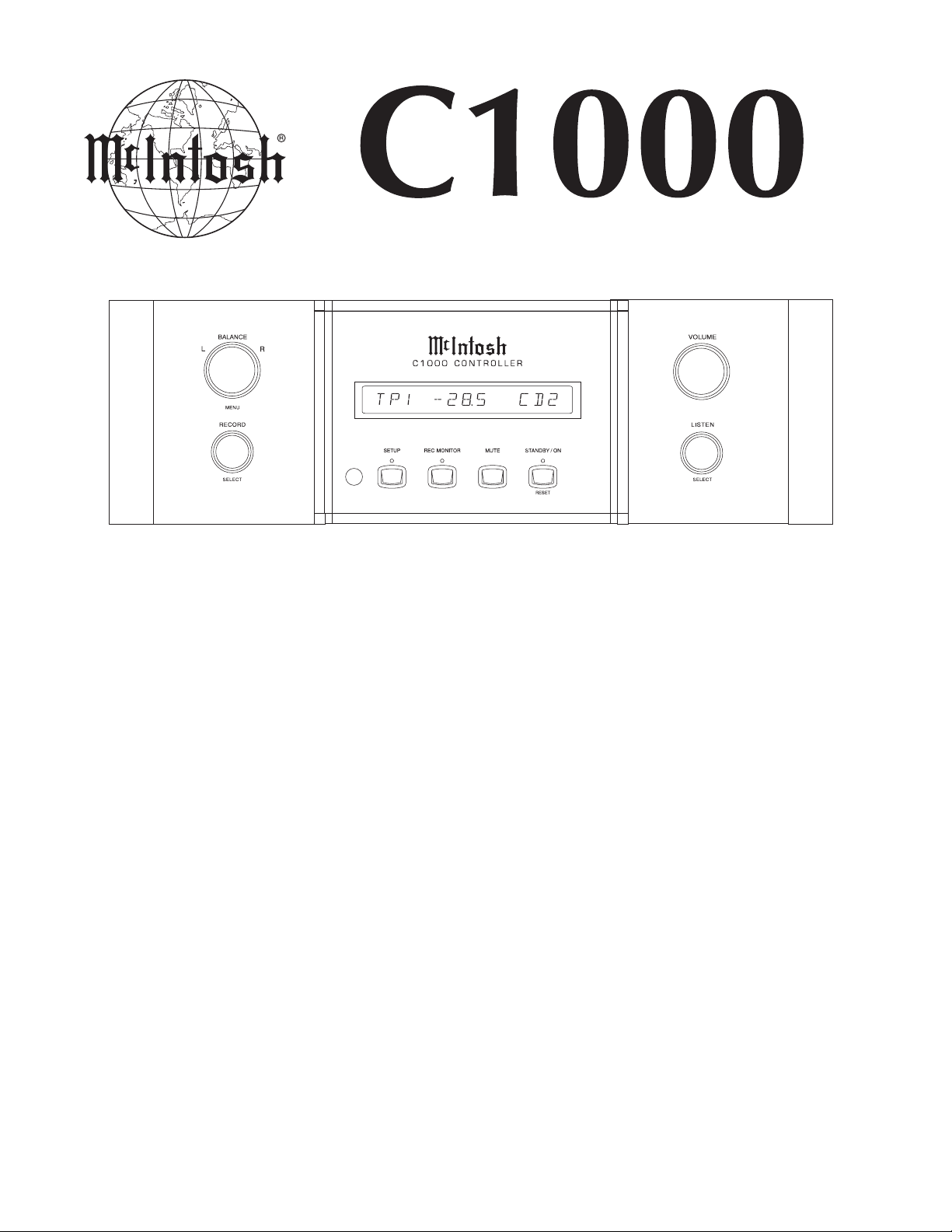
CONTROLLER
CONTENTS
Performance Specifications ........................................ 2
Notes ......................................................................... 2
Rear Panel .................................................................. 3
Section Location ........................................................ 3
Block Diagram ........................................................... 4
Interconnection Diagram ...................................... 5 - 6
Power Supply Schematic and PCB...................... 7 - 10
SERVICE MANUAL
Display Schematic and PCB .............................. 11 - 14
Pushbutton Schematic and PCB ........................ 15 - 16
Power Control Schematic and PCB.................... 17 - 18
Data Schematic and PCB................................... 19 - 20
Parts List ............................................................ 21 - 23
Exploded View and Parts List ............................. 25 - 26
Repacking Instructions ............................................. 2 9
Page 2

PERFORMANCE SPECIFICATIONS
Power Requirements
100 Volts, 50/60Hz at 120 watts
110 Volts, 50/60Hz at 120 watts
120 Volts, 50/60Hz at 120 watts
220 Volts, 50/60Hz at 120 watts
230 Volts, 50/60Hz at 120 watts
240 Volts, 50/60Hz at 120 watts
Note: Refer to the rear panel of the C1000 Controller for the
correct voltage.
General Specifications
Overall Dimensions
C1000C:
Width is 17-1/2 inches (44.45cm)
Height is 6 inches (15.24cm) including feet
Depth is 24 inches (61.0cm) including the Front Panel, Knobs and
Interconnect Cables
C1000P:
Width is 17-1/2 inches (44.45cm)
Height is 6 inches (15.24cm) including feet
Depth is 24 inches (61.0cm) including the Front Panel and
Interconnect Cables
1
1
C1000T:
Width is 17-1/2 inches (44.45cm)
Height is 6 inches (15.24cm) including feet
Depth is 24 inches (61.0cm) including the Front Panel
and Interconnect Cables
Weight
C1000C - 39.0 pounds (17.7 kg) net
61.4 pounds (27.9 kg) in shipping carton
C1000P - 33.0 pounds (15.0 kg) net
53.6 pounds (24.3 kg) in shipping carton
C1000T - 34.0 pounds (15.4 kg) net
54.6 pounds (24.8 kg) in shipping carton
1
Interconnect Cables are supplied with the C1000
Preamplifier and C1000 T ube Preamplifier. They are used
to connect Preamplifier(s) to the C1000 Controller.
1
NO TES
1. The heavy notes on the schematic denote the primary
signal path.
2. Unless otherwise noted, all voltages indicated on the
schematics are measured under the following conditions:
a. AC input at 120 volts, 50/60Hz.
b. All voltages are +/-10% with respect to ground. A
high impedance (10 megaohm) voltmeter must be used.
3 . Unless otherwise specified:
a. Resistor values are in ohms.
b. Capacitor values are microfarads (uF).
c. Inductor values are in microhenries (uH).
4 . On PC board drawings, Square pad indicates:
a. Polarized Capacitors - Positive
b. Diodes - Cathode
c. Others - Pin 1
5. WARNING
Parts marked with the symbol have critical
characteristics. Use only replacement parts recom
mended by the manufacturer.
6 . Use McIntosh Remote Control Model HR052 with the
MVP861.
2
Page 3
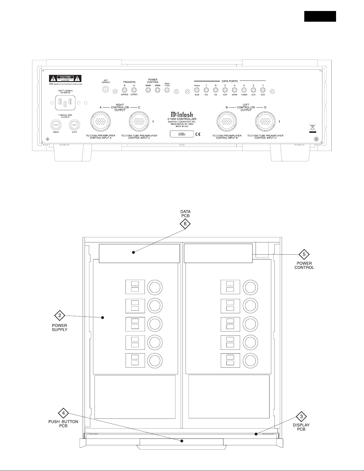
REAR PANEL
SECTION LOCATIONS
C1000
CONTROLLER
TOP VIEW WITH COVER REMOVED
3
Page 4
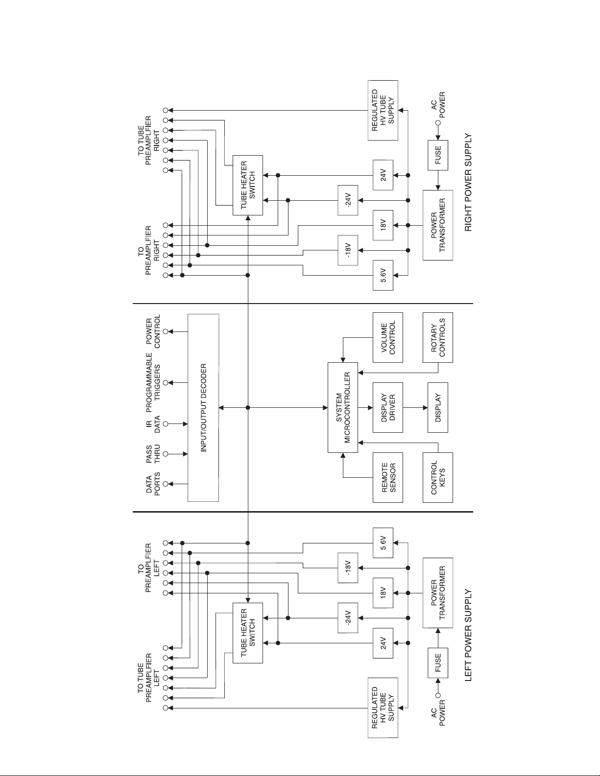
BLOCK DIAGRAM
4
Page 5
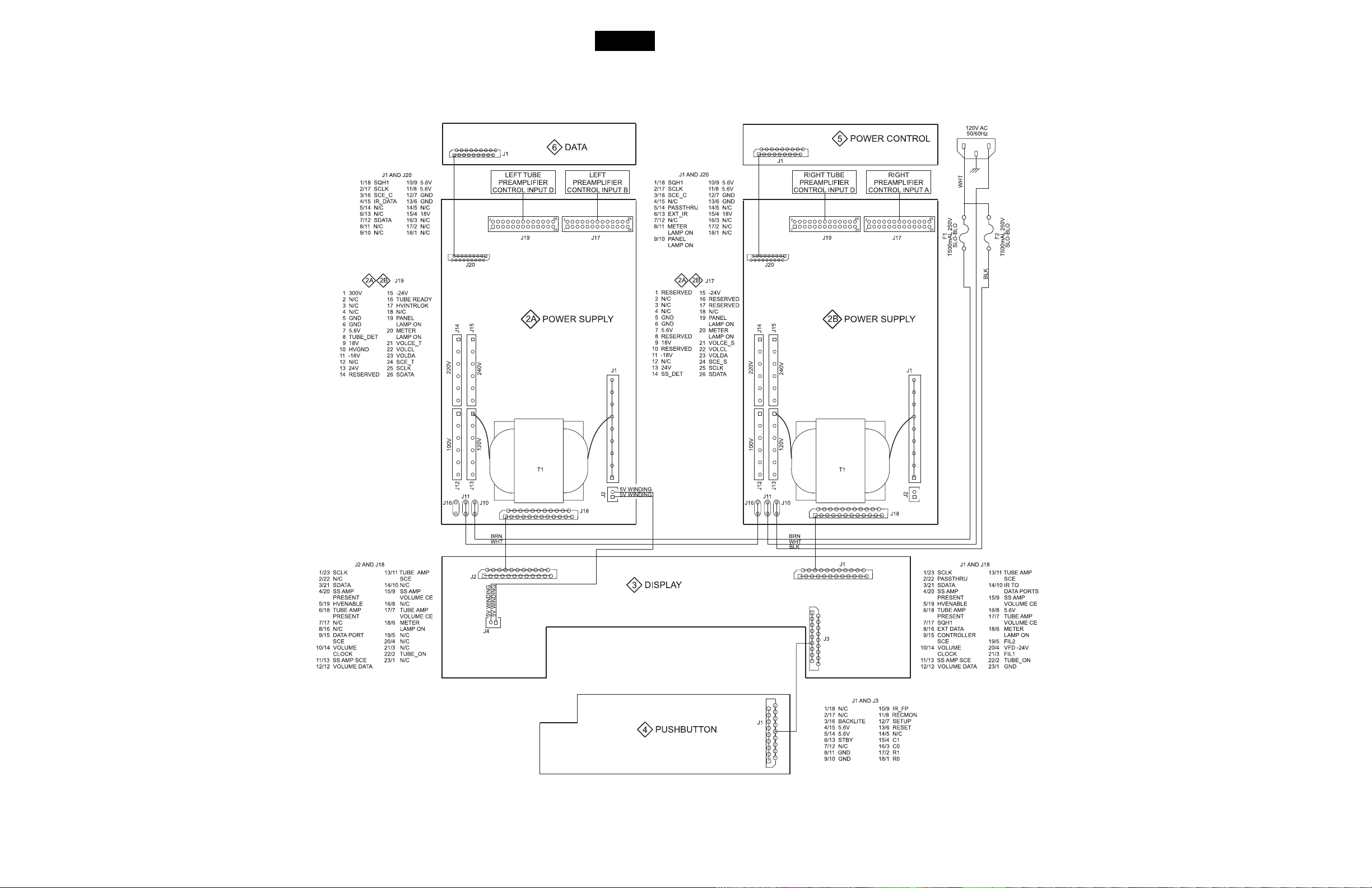
INTERCONNECT
C1000
CONTROLLER
5
6
Page 6
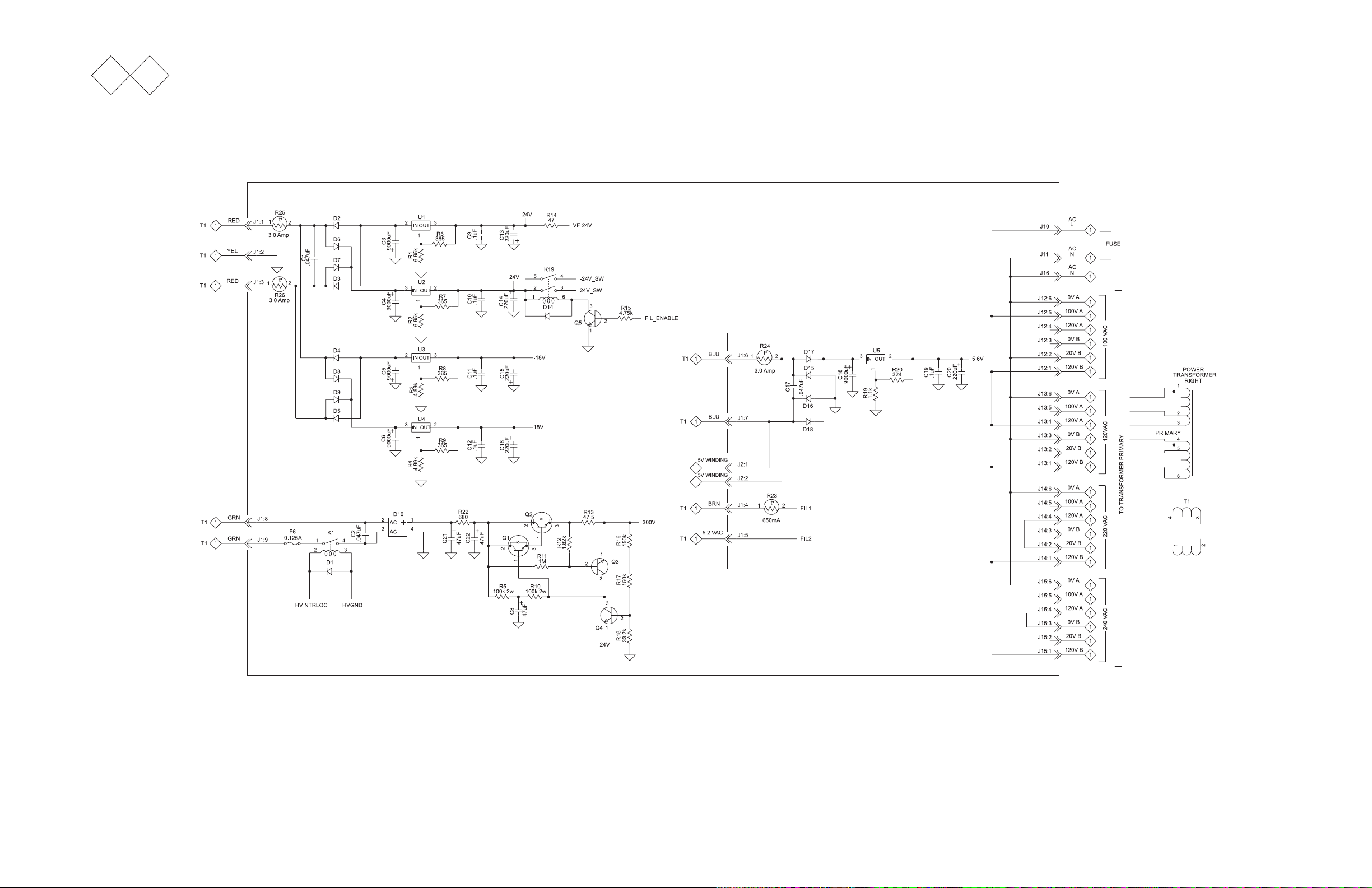
2A 2B
POWER SUPPLY
050098 SCH 1 OF 2
7
8
Page 7

2A 2B
POWER SUPPLY
C1000
CONTROLLER
050098 SCH 2 OF 2 and PCB
9 10
Page 8

3
DISPLAY
050099 SCH 1 OF 2
11 12
Page 9

C1000
CONTROLLER
3
DISPLAY
050099 SH 2 OF 2 and PCB
13
14
Page 10
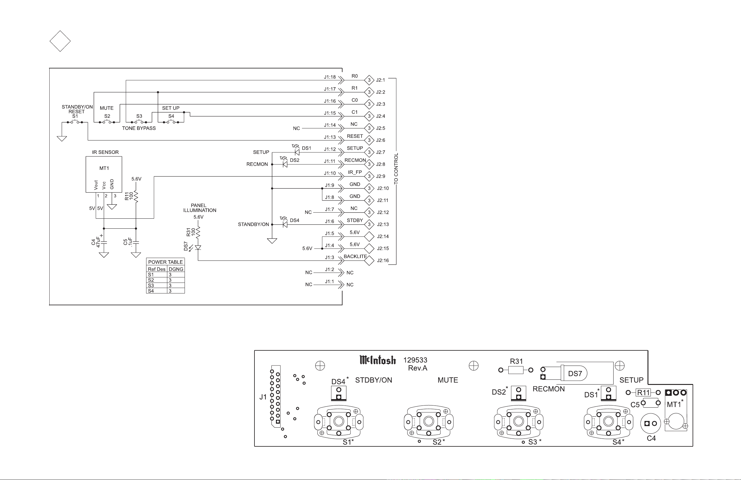
4
PUSHBUTTON
050100 SCH and PCB
15
16
Page 11

C1000
CONTROLLER
5
POWER CONTROL
050196 SCH and PCB
17
18
Page 12

6
DAT A
050101 SCH and PCB
19
20
Page 13

PARTS LISTS
050098 POWER SUPPL Y PCB
Ref No. Description Part No.
C1 CAP POLY .047UF 10% 250VDC 064364
C2 CAP POLY .047UF 10% 1000VDC 064434
C3 CAP ELECT 9000UF 40V 066474
C4 CAP ELECT 9000UF 40V 066474
C5 CAP ELECT 9000UF 40V 066474
C6 CAP ELECT 9000UF 40V 066474
C8 CAP ELECT 47UF 450V 066497
C9 CAP MONO .1uF 50V 20% Z5U 061305
C10 CAP MONO .1uF 50V 20% Z5U 061305
C11 CAP MONO .1uF 50V 20% Z5U 061305
C12 CAP MONO .1uF 50V 20% Z5U 061305
C13 CAP ELECT 220UF 50V 20% 066254
C14 CAP ELECT 220UF 50V 20% 066254
C15 CAP ELECT 220UF 50V 20% 066254
C16 CAP ELECT 220UF 50V 20% 066254
C17 CAP POLYPROP .047UF 10% 250VDC 064364
C18 CAP ELECT 9000UF 40V 066474
C19 CAP MONO .1uF 50V 20% Z5U 061305
C20 CAP ELECT 220UF 50V 20% 066254
C21 CAP ELECT 47UF 450V 066497
C22 CAP ELECT 47UF 450V 066497
D1 DIODE SILICON 1N4148 070047
D2 DIODE SIL 400 PIV @ 1.5A 070031
D3 DIODE SIL 400 PIV @ 1.5A 070031
D4 DIODE SIL 400 PIV @ 1.5A 070031
D5 DIODE SIL 400 PIV @ 1.5A 070031
D6 DIODE SIL 400 PIV @ 1.5A 070031
D7 DIODE SIL 400 PIV @ 1.5A 070031
D8 DIODE SIL 400 PIV @ 1.5A 070031
D9 DIODE SIL 400 PIV @ 1.5A 070031
D10 DIODE BRID RECT 1000V 6A 070165
D14 DIODE SILICON 070047
D15 DIODE RECT SI 3A 100V 070041
D16 DIODE RECT SI 3A 100V 070041
D17 DIODE RECT SI 3A 100V 070041
D18 DIODE RECT SI 3A 100V 070041
F6 0.125A 5x20 fuse IEC 089094
J1 HEADER 9 CIRCUIT POST NATURAL 117724
J2 HEADER 2 PIN LATCHING 117766
J10 BLADE FASTON W/FEET 117708
J11 BLADE FASTON W/FEET 117708
J12 CONN PCB MOUNT POWER RED 117719
J13 CONN PCB MOUNT POWER RED 117719
J14 CONN PCB MOUNT POWER RED 117719
J15 CONN PCB MOUNT POWER RED 117719
J16 BLADE FASTON W/FEET 117708
J17 HEADER SHROUDED 2ROW 26PIN V 117870
J18 CONN 23 PIN FFC 117715
J19 HEADER SHROUDED 2ROW 26PIN V 117870
J20 CONN FFC 18PIN 117765
K1 RELAY POWER TV5 24V 087069
K19 24v 22ma 1100ohms 087057
Q1 TRANSISTOR: NPN POWER 132295
Q2 TRANSISTOR: NPN POWER 132295
Q3 TRANSISTOR NPN SILICON 132171
Q4 TRANSISTOR NPN 132136
Q5 TRANSISTOR NPN 132223
R1 RES MF 6.65K OHM 1% 1/4W 144449
R2 RES MF 6.65K OHM 1% 1/4W 144449
CONTROLLER
Ref No. Description Part No.
R3 RES MF 4.99K 1% 1/4W 144098
R4 RES MF 4.99K 1% 1/4W 144098
R5 RES MO 100K 5% 2W 144438
R6 RES MF 365 OHM 1% 1/4W 144071
R7 RES MF 365 OHM 1% 1/4W 144071
R8 RES MF 365 OHM 1% 1/4W 144071
R9 RES MF 365 OHM 1% 1/4W 144071
R10 RES MO 100K 5% 2W 144438
R11 RES MF 1M 1/4W 144269
R12 RES MF 1.82K 1% 1/4W 144296
R13 RES MF 47.5 OHM 1% 1/4W 144442
R14 RES MET OX 47 OHM .5W 5% 137096
R15 RES MF 4.75K 1% 1/4W 144097
R16 RES MF 150K 1% 1/4W 144419
R17 RES MF 150K 1% 1/4W 144419
R18 RES MF 33.2K 1% 1/4W 144015
R19 RES MF 1.1K 1% 1/4W 144091
R20 RES MF 324 OHM 1% 1/4W 144338
R21 RES MF 22.1K 1% 1/4W 144187
R22 RES MET OX 680 OHM .5W 5% 137093
R23 FUSE PTC RESETTABLE 144488
R24 POLYSWITCH RXE300 144267
R25 POLYSWITCH RXE300 144267
R26 POLYSWITCH RXE300 144267
T1 R-Core Power Transformer 159358
U1 LM337 1.5A Adj Reg/Htsk 6298B-CNE42 133334
U2 LM317T 1.5A Adjustable Reg 133333
U3 LM337 1.5A Adj Reg/Htsk 6298B-CNE42 133334
U4 LM317T 1.5A Adjustable Reg 133333
U5 LM317T 1.5A Adjustable Reg 133333
U6 IC OCT 3-ST NI BF/LD/LR 133157
U7 IC OCT 3-ST NI BF/LD/LR 133157
050099 DISPLA Y PCB
C1 CAP ELECT 10UF 50V 066445
C2 CAP ELECT 47UF 35V 066446
C3 CAP MONO .1UF 50V 20% 061305
C4 CAP MONO .1UF 50V 20% 061305
C5 CAP MONO .1UF 50V 20% 061305
C6 CAP MONO .1UF 50V 20% 061305
C7 CAP MONO 220PF 200V 10% 061301
C8 CAP MONO .1UF 50V 20% 061305
C9 CAP ELECT 10UF 50V 066445
C10 CAP ELECT 10UF 50V 066445
C11 CAP MONO 33PF 200V 5%NPO T&R 061307
C12 CAP MONO 33PF 200V 5%NPO T&R 061307
C13 CAP MONO .1UF 50V 20% 061305
C14 CAP MONO .1UF 50V 20% 061305
D1 DIODE SILICON 1N4148 070047
D2 DIODE SILICON 070047
D3 DIODE SILICON 070047
D4 DIODE SILICON 070047
D5 DIODE ZENER 6.2V 5% 500MW 070085
D6 DIODE SILICON 070047
D7 DIODE SILICON 070047
DS1 LED BAL PCB 058109
DS2 LED GRN 5MM HI-INTENSITYVF[V] 3.5 058165
DS3 LED GRN 5MM HI-INTENSITY VF[V] 3.5 058165
21
C1000
Page 14

Ref No. Description Part No.
DS4 LED GRN 5MM HI-INTENSITY VF[V] 3.5 058165
DS5 LED GRN 5MM HI-INTENSITY VF[V] 3.5 058165
DS6 LED GRN 5MM HI-INTENSITY VF[V] 3.5 058165
DS8 16 Digits VF display 058169
J1 CONN 23 PIN FFC 117715
J2 CONN 23 PIN FFC 117715
J3 CONN FFC 18PIN 117765
J4 HEADER 2 PIN LATCHING 117766
K1 RELAY REED FORM 1A 5V 500 OHMS 087050
Q1 TRANSISTOR NPN 132223
Q2 TRANSISTOR PNP 132224
Q3 TRANSISTOR NPN 132223
Q4 TRANSISTOR NPN 132223
Q5 TRANSISTOR NPN 132223
Q6 TRANSISTOR NPN 132223
Q7 TRANSISTOR NPN 132223
Q8 TRANSISTOR PNP 132224
Q9 TRANSISTOR NPN 132223
R1 RES MF 475K 1% 1/4W 144364
R2 RES MF 10K 1% 1/4W 144053
R3 RES MF 10K 1% 1/4W 144053
R4 RES MF 100 OHM 1% 1/4W 144196
R5 RES MF 10 OHM 1% 1/4W 144157
R6 RES MF 10K 1% 1/4W 144053
R7 RES MF 47.5K 1% 1/4W 144108
R8 RES NETWORK 9X-1-223 144238
R9 RES NET 10K X8 RES B 144253
R11 RES MF 324 OHM 1% 1/4W 144338
R12 RES MF 324 OHM 1% 1/4W 144338
R13 RES MF 10K 1% 1/4W 144053
R14 RES MF 10K 1% 1/4W 144053
R15 RES MF 324 OHM 1% 1/4W 144338
R16 RES NETWORK 9X-1-223 144238
R17 RES NETWORK 9X-1-223 144238
R18 RES NETWORK 9X-1-223 144238
R19 RES MF 1K 1% 1/4W 144090
R20 RES MF 100 OHM 1% 1/4W 144196
R21 RES MF 100 OHM 1% 1/4W 144196
R22 RES MF 100 OHM 1% 1/4W 144196
R23 RES MF 100 OHM 1% 1/4W 144196
R24 RES MF 100 OHM 1% 1/4W 144196
R25 RES MF 324 OHM 1% 1/4W 144338
R26 RES MF 324 OHM 1% 1/4W 144338
R27 RES MF 2.21K 1% 1/4W 144298
R28 RES MF 100K 1% 1/4W 144113
R29 RES WW 100 OHM 10% 2W BWH 139134
R30 RES MF 475 OHM 1% 1/4W 144086
R31 RES MF 475 OHM 1% 1/4W 144086
R32 RES MF 10K 1% 1/4W 144053
R33 RES MF 10K 1% 1/4W 144053
R34 RES MF 10K 1% 1/4W 144053
R35 RES MF 10K 1% 1/4W 144053
R36 RES MF 10K 1% 1/4W 144053
R37 RES MF 47.5K 1% 1/4W 144108
R38 RES MF 221K 1% 1/4W 144421
R39 RES MF 47.5K 1% 1/4W 144108
R40 RES MF 47.5K 1% 1/4W 144108
S1 16encoder 129294
S2 16encoder 129294
S3 ENCODER OPTICAL ROTARY 146246
S4 16encoder 129294
U1 IC NOR 2 INPUT X 4 133176
U2 IC MICRO RESET POS 133241
U3 IC PROGRAMMED c45 V1.00 133504
U4 IC NAND 2 INPUT X 4 133161
Ref No. Description Part No.
U5 IC SHFT REG SER-PAR 133186
U6 IC 8BIT DRIVER 133461
U7 VFD Controller 16 Seg x 14 digit 133510
U8 IC OCT 3-ST NI BF/LD/LR 133157
U9 IC CMOS EPROM 133249
Y1 RESONATOR CERAMIC 12.0MHZ W/CAP 180059
Y2 CERAMIC RESONATOR 2MHZ 180047
Y3 RESONATOR CERAMIC 2.0MHZ W/CAP 180064
050100 PUSHBUTTON PCB
C4 47uf 16v small can 066380
C5 CAP MONO .1UF 50V 20% Z5U 061305
DS1 LED SQUARE RED 058109
DS2 LED SQUARE RED 058109
DS4 LED SQUARE RED 058109
DS7 LED GRN 5MM HI-INTENSITY VF[V] 3.5 058165
J1 CONN FFC 18PIN 117765
MT1 VISHAY TSOP2238YA1 121046
R11 RES MF 100 OHM 1% 1/4W 144196
R31 RES MF 100 OHM 1% 1/4W 144196
S1 SWITCH PB TACT 150058
S2 SWITCH PB TACT 150058
S3 SWITCH PB TACT 150058
S4 SWITCH PB TACT 150058
050101 DAT A PCB
C4 CAP MONO 220PF 100V 10% NPO 061301
C5 CAP MONO .1uF 50V 20% Z5U 061305
GP1 BRACKET PCB CARD MOUNTING 003611
GP2 BRACKET PCB CARD MOUNTING 003611
J1 CONN FFC 18PIN 117765
J4 JACK HEADPHONE STEREO 1/8IN 117759
J5 JACK HEADPHONE STEREO 1/8IN 117759
J6 JACK HEADPHONE STEREO 1/8IN 117759
J7 JACK HEADPHONE STEREO 1/8IN 117759
J8 JACK HEADPHONE STEREO 1/8IN 117759
J9 JACK HEADPHONE STEREO 1/8IN 117759
J10 JACK HEADPHONE STEREO 1/8IN 117759
J11 JACK HEADPHONE STEREO 1/8IN 117759
R1 RES MF 1K 1% 1/4W 144090
R2 RES MF 1K 1% 1/4W 144090
R4 RES MF 1K 1% 1/4W 144090
R13 RES MF 100 OHM 1% 1/4W 144196
R14 RES MF 100 OHM 1% 1/4W 144196
R15 RES MF 100 OHM 1% 1/4W 144196
R16 RES MF 100 OHM 1% 1/4W 144196
R17 RES MF 100 OHM 1% 1/4W 144196
R18 RES MF 100 OHM 1% 1/4W 144196
R19 RES MF 100 OHM 1% 1/4W 144196
R20 RES MF 100 OHM 1% 1/4W 144196
R21 RES MF 100 OHM 1% 1/4W 144196
U1 IC SHFT REG SER-PAR 133186
U2 LB1720 133180
050196 POWER CONTROL PCB
C1 CAP MONO .1uF 50V 20% Z5U 061305
C2 CAP ELECT 10UF 50V 066445
C3 CAP MONO .1uF 50V 20% Z5U 061305
C4 CAP MONO 220PF 100V 10% NPO 061301
C6 CAP MONO 1000PF 50V 10% NPO 061303
C7 CAP MONO .1uF 50V 20% Z5U 061305
C8 CAP ELECT 10UF 50V 066445
C9 CAP MONO .1uF 50V 20% Z5U 061305
C10 CAP MONO 100PF 100V 10% 061300
C11 CAP MONO 100PF 100V 10% 061300
22
Page 15

Ref No. Description Part No.
D1 DIODE SILICON 1N4148 070047
GP1 BRACKET PCB CARD MOUNTING 003611
GP2 BRACKET PCB CARD MOUNTING 003611
J1 CONN FFC 18PIN 117765
J2 CONN GOLD F RIGHT ANGLE 117661
J3 JACK HEADPHONE STEREO 1/8IN 117759
J12 JACK HEADPHONE STEREO 1/8IN 117759
J13 JACK HEADPHONE STEREO 1/8IN 117759
J14 JACK HEADPHONE STEREO 1/8IN 117759
J15 JACK HEADPHONE STEREO 1/8IN 117759
Q1 TRANSISTOR NPN 132223
Q2 TRANSISTOR NPN 132223
Q3 TRANSISTOR NPN 132223
Q4 TRANSISTOR NPN 132223
Q5 TRANSISTOR NPN 132223
R1 RES MF 1K 1% 1/4W 144090
R2 RES MF 1K 1% 1/4W 144090
R3 RES MF 100K 1% 1/4W 144113
R4 RES MF 1K 1% 1/4W 144090
R5 RES MF 221K 1% 1/4W 144421
R6 RES MF 100K 1% 1/4W 144113
R7 RES MF 40.2K 1% 1/4W 144107
R8 RES MF 40.2K 1% 1/4W 144107
R9 RES MF 1K 1% 1/4W 144090
R10 RES MF 221 OHM 1% 1/4W 144172
R11 RES MF 100K 1% 1/4W 144113
R12 RES MF 221K 1% 1/4W 144421
R13 RES MF 100 OHM 1% 1/4W 144196
R22 RES MF 2.21 OHM 1% 1/4W 144378
R23 RES MF 475K 1% 1/4W 144364
R24 RES MF 475K 1% 1/4W 144364
C1000
CONTROLLER
Ref No. Description Part No.
R25 RES MF 22.1K 1% 1/4W 144187
R26 RES MF 22.1K 1% 1/4W 144187
R27 RES MF 3.32K 1% 1/4W 144095
R28 RES MF 3.32K 1% 1/4W 144095
R29 RES MF 150K 1% 1/4W 144419
R30 RES MF 47.5K 1% 1/4W 144108
R31 RES MF 150K 1% 1/4W 144419
R32 RES MF 47.5K 1% 1/4W 144108
R33 RES MF 4.99K 1% 1/4W 144098
R34 RES MF 4.99K 1% 1/4W 144098
R35 RES POL YSWITCH RXE030 144240
R36 RES POL YSWITCH RXE030 144240
R37 RES MF 100 OHM 1% 1/4W 144196
R38 RES MF 182 OHM 1/4W 1% 144273
R39 RES MF 182 OHM 1/4W 1% 144273
R40 RES MF 182 OHM 1/4W 1% 144273
R41 RES MF 182 OHM 1/4W 1% 144273
R42 RES MF 182 OHM 1/4W 1% 144273
R43 RES MF 150K 1% 1/4W 144419
R44 RES MF 182 OHM 1/4W 1% 144273
R45 RES MF 150K 1% 1/4W 144419
R46 RES MF 4.75K 1% 1/4W 144097
R47 RES MF 4.75K 1% 1/4W 144097
U1 1.25A Low Dropout Regulator 133431
U2 1.25A Low Dropout Regulator 133431
U3 IC SHFT REG SER-PAR 133186
U4 IC OPERATIONAL AMPLIFIER 133189
U5 IC NAND SCHMIT 2-IN X 4 133192
U6 IC AND 2 INPUT X 4 133175
23
Page 16

NOTES
24
Page 17

EXPLODED VIEW AND PARTS LIST
C1000
CONTROLLER
25
26
Page 18

NOTES
27
28
Page 19

REPACKING INSTRUCTIONS
C1000
CONTROLLER
29
Page 20

CONTROLLER
SERVICE MANUAL
The continuous improvement of its products is the policy of McIntosh Laboratory Incorporated, who reserve the right to improve design without
notice. Because of the constant upgrading of McIntosh products’ circuitry and components, the Company cannot insure, and does not warrant, the
accuracy of the within schematic material, which is intended for information only.
McINTOSH LABORATORY, INC., 2 CHAMBERS STREET, BINGHAMTON, NEW YORK 13903 Printed in U.S.A. Part Number 040XXX
 Loading...