

Mcintosh C1000 owners Manual
Controller/Preamplifier/Tube Preamplifier
C1000
Owner’s Manual
McIntosh Laboratory, Inc. 2 Chambers Street Binghamton, New York 13903-2699 Phone: 607-723-3512 FAX: 607-724-0549

The lightning flash with arrowhead,
within an equilateral triangle, is intended to alert the user to the presence
of uninsulated “dangerous voltage”
within the product’s enclosure that may
be of sufficient magnitude to constitute
a risk of electric shock to persons.
The exclamation point within an
equilateral triangle is intended to
alert the user to the presence of important operating and maintenance
(servicing) instructions in the literature accompanying the appliance.
WARNING - TO REDUCE RISK OF
FIRE OR ELECTRICAL SHOCK, DO
NOT EXPOSE THIS EQUIPMENT TO
RAIN OR MOISTURE.
IMPORTANT SAFETY
INSTRUCTIONS!
PLEASE READ THEM BEFORE
OPERATING THIS EQUIPMENT.
1. Read these instructions.
2. Keep these instructions.
3. Heed all warnings.
4. Follow all instructions.
5. Do not use this apparatus near water.
6. Clean only with a dry cloth.
7. Do not block any ventilation openings. Install in
accordance with the manufacturer’s instructions.
8. Do not install near any heat sources such as
radiators, heat registers, stoves, or other
apparatus (including amplifiers) that produce heat.
9. Do not defeat the safety purpose of the polarized
or grounding-type plug. A polarized plug has two
blades with one wider than the other. A grounding
type plug has two blades and a third grounding
prong. The wide blade or the third prong are
provided for your safety. If the provided plug
does not fit into your outlet, consult an electrician
for replacement of the obsolete outlet.
10. Protect the power cord from being walked on or
pinched particularly at plugs, convenience
receptacles, and the point where they exit from
the apparatus.
NO USER-SERVICEABLE PARTS
INSIDE. REFER SERVICING TO
QUALIFIED PERSONNEL.
To prevent the risk of electric shock, do not remove cover or
back. No user-serviceable parts inside.
11. Only use attachments/accessories specified by the
manufacturer.
12. Use only with the cart, stand, tripod, bracket, or
table specified by the manufacturer, or
sold with the apparatus. When a cart
is used, use caution when moving the
cart/apparatus combination to avoid
injury from tip-over.
13. Unplug this apparatus during lightning storms or
when unused for long periods of time.
14. Refer all servicing to qualified service personnel.
Servicing is required when the apparatus has been
damaged in any way, such as power-supply cord
or plug is damaged, liquid has been spilled or
objects have fallen into the apparatus, the
apparatus has been exposed to rain or moisture,
does not operate normally, or has been dropped.
15. Do not expose this equipment to dripping or
splashing and ensure that no objects filled with
liquids, such as vases, are placed on the
equipment.
16. To completely disconnect this equipment from the
a.c. mains, disconnect the power supply cord
plug from the a.c. receptacle.
17. The mains plug of the power supply cord shall
remain readily operable.
18. Do not place the protective blue cloth cover on
the equipment when the power supply cord is
connected.
19. Do not expose batteries to excessive heat such as
sunshine, fire or the like.
2
Thank You
Your decision to own this McIntosh C1000 Controller together with the Preamplifier and/or Tube Preamplifier ranks
you at the very top among discriminating music listeners.
You now have “The Best.” The McIntosh dedication to
“Quality,” is assurance that you will receive many years of
musical enjoyment from this unit.
Please take a short time to read the information in this
manual. We want you to be as familiar as possible with all
the features and functions of your new McIntosh.
Table of Contents
Safety Instructions ............................................................ 2
Thank You and Please Take a Moment ............................. 3
Technical Assistance and Customer Service ..................... 3
Table of Contents .............................................................. 3
Important Information and Connector Information ........... 4
Introduction ....................................................................... 4
Performance Features ....................................................... 5
Dimensions ..................................................................... 6-8
Installation ................................................................... 9-10
Please Take A Moment
The serial number, purchase date and McIntosh Dealer
name are important to you for possible insurance claim or
future service. The spaces below have been provided for
you to record that information:
Dealer Name
Purchase
Date
Model
Numbe r
Serial
Numbe r
Technical Assistance
If at any time you have questions about your McIntosh
product, contact your McIntosh Dealer who is familiar with
your McIntosh equipment and any other brands that may be
part of your system. If you or your Dealer wish additional
help concerning a suspected problem, you can receive technical assistance for all McIntosh products at:
McIntosh Laboratory, Inc.
2 Chambers Street
Binghamton, New York 13903
Phone: 607-723-1545
Fax: 607-724-0549
Customer Service
If it is determined that your McIntosh product is in need of
repair, you can return it to your Dealer. You can also return
it to the McIntosh Laboratory Service Department. For assistance on factory repair return procedure, contact the
McIntosh Service Department at:
McIntosh Laboratory, Inc.
2 Chambers Street
Binghamton, New York 13903
Phone: 607-723-3515
Fax: 607-723-1917
Copyright 2005, 2006 © by McIntosh Laboratory, Inc.
Connections:
C1000 Rear Panels .......................................................... 11
C1000 Controller Rear Panel Connections
(Separate Sheet) ......................................................... Mc1A
C1000 Preamplifier and Tube Preamplifier
Rear Panel Connections (Separate Sheet) ..... Mc2A, Mc2B
How to Connect the C1000 Controller and
C1000 Preamplifier .....................................................12-13
Μ Μ
Connection Diagrams (Separate Sheet)......... Mc3A,
Μc
Μ Μ
3Β3Β
3Β
3Β3Β
How to Connect the C1000 Controller and
C1000 Tube Preamplifier ............................................ 14-15
Μ Μ
Connection Diagrams (Separate Sheet)......... Mc4A,
Μc
Μ Μ
4Β4Β
4Β
4Β4Β
How to Connect the C1000 Controller, C1000 Preamplifier
and C1000 Tube Preamplifier ..................................... 16-17
Μ Μ
Connection Diagrams (Separate Sheet)......... Mc5A,
Μc
Μ Μ
5Β5Β
5Β
5Β5Β
How to Connect the C1000 with the Balanced Line Integra-
tor ................................................................................ 17-18
How to Connect the C1000 with Passthru Mode ............. 19
Front Panel Features:
C1000 Controller Front Panel Controls,
Displays and Push-buttons ............................................... 20
C1000 Preamplifier and C1000 Tube Preamplifier
Front Panel Displays and Jack ......................................... 21
Setup:
How to Operate the Setup Modes ............................... 22-33
Remote Control:
Remote Control Push-buttons .......................................... 34
How to operate the Remote Control ................................. 35
Operation:
How to Operate the C1000 ......................................... 36-40
Additional Information:
Photos ......................................................................... 41-43
Technical Description..................................................44-48
Μ Μ
Block Diagrams (Separate Sheet) ................. Mc6A,
Μc
Μ Μ
6Β6Β
6Β
6Β6Β
Specifications ..............................................................49-50
Packing Instruction .......................................................... 51
3
Important Information
1. The C1000 System consists of two or three separate
chassis. The C1000 Controller Chassis will be referred to
as the C1000C throughout this Owner’s Manual. In a
similar manner, the C1000 Preamplifier (Solid State)
Chassis will be referred to as the C1000P and the C1000
Tube Preamplifier Chassis will be referred to as the C1000T
throughout this Owner’s Manual.
2. For additional information on Audio Connections, refer to
the Owner’s Manual(s) for the component(s).
3. Connecting Cables and Connectors are available from the
McIntosh Parts Department:
Data, Power Control and Trigger Cable Part No.
170-202
Six foot, shielded 2 conductor, with 1/8 inch stereo mini
phone plug on each end.
Controller to Preamplifier Cable Part No. 171-745
Three foot, shielded 24 conductor, male-to-male custom
cable, two required between Controller and Preamplifier.
4. The Main AC Power Cable going to the C1000C and any
other McIntosh Component(s) should not be connected to
an AC Power Outlet until all the system components are
connected together. When the C1000C and other McIntosh
Components are in their Standby Power Off Mode, the
Microprocessor’s Circuitry inside each component is active
and communication is occurring between them. Failure to
do so could result in malfunctioning of some or all of the
system’s normal operations.
5. Up to four sensors can be wired in parallel for Remote
Control of the C1000 from other rooms.
6. Balanced and Unbalanced Inputs and Outputs can be
mixed. For example, you may connect signal sources to
Unbalanced Inputs and send signals from the Balanced
Outputs. You can also use Balanced and Unbalanced
outputs simultaneously, connected to different power
amplifiers.
7. A McIntosh Power Controller may be added to the C1000 to
provide AC Power Switching to components that do not
have Power Control Connections. See your McIntosh
Dealer for additional information.
8. When the C1000P and C1000T Preamplifiers are both
connected to the same C1000C Controller ( refer to pages
20 and 21):
A. The Record Link Inputs on both preamplifiers need
to be connected together, thus allowing sharing of
their inputs for recording purposes.
B. The McIntosh MDA1000 D/A Converter may be
connected to either the C1000P or C1000T
Preamplifier.
9. Sound Intensity is measured in units called Decibels and
“dB” is the abbreviation.
10. If the C1000P and/or C1000T Preamplifiers 21 conductor
custom interconnect cable(s) become temporarily
disconnected from the C1000C when it is On or in Stand-by
Mode, a cable error message will appear on the C1000C.
Remove the AC Power Cord from the C1000C, connect the
disconnected 21 conductor custom interconnect cable(s) and
then reconnected the AC Power Cord. The C1000 System
will automatically reset itself to the previous configuration.
11. When a C1000P or C1000T Preamplifier is added to an
already existing C1000 System, the C1000C will
automatically recognize the need to re-configure the C1000
System, refer to page 41 for additional information.
Connector Information
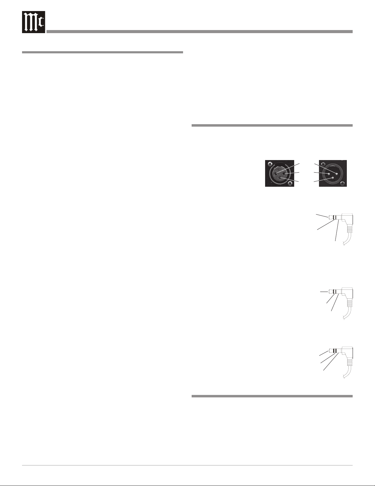
XLR Connectors
Below is the Pin configuration for the XLR Balanced Input
and Output Connectors on the C1000 Preamplifier. Refer to
the diagram for connection:
PIN 1: Shield/Ground
PIN 2: + Signal
PIN 3: - Signal
Pin 2
Pin 1
Pin 3
Main Power Control Connectors
The C1000’s Power Control Outputs provide a +5 volt signal. An additional connection is for
controlling the illumination of a Power
Amplifier Output Meter. Use a 1/8
inch stereo mini phone plug to connect
to the Power Control Input on other
Power
Control
Meter
Illumination
Control
Ground
McIntosh Components.
Trigger Control Connectors
The C1000’s Trigger Control Outputs provide either a +5
volt (default) or +12 volt signal (refer to
page 25). Use a 1/8 inch stereo mini
phone plug to connect to the Power
Control Input on McIntosh and/or nonMcIntosh components.
Trigger
Control
N/C
Ground
Data and IR Port Connectors
The C1000’s Data Port Output provides Remote Control
Signals. Use a 1/8 inch stereo mini
phone plug to connect to the Data
Port Inputs on McIntosh Source
Units.
Data Signal
N/C
Data Ground
Introduction
The C1000 Preamplifiers with a Controller are the finest
audio preamplifiers McIntosh has ever created. No design
compromises were allowed in the quest for a preamplifier,
both Solid State and Tube with absolute accuracy, total
sonic purity and virtual elimination of distortion and audible
noise. For those who have been searching for the “Best in
Preamplifiers”, your wait is over.
4

Performance Features
Introduction and Performance Features
••
• Dual Chassis with Dual Mono Design
••
The Dual Chassis design completely separates all power
supply, microprocessor and control circuits from the pure
audio circuits for total noise isolation. To further aid in
channel isolation the circuitry for both channels is totally
separate, physically isolated and shielded. The C1000 incorporates two identical power supplies one for each channel,
to help assure total channel isolation.
••
• Balanced and Unbalanced Inputs/Outputs
••
Four balanced high level inputs and three balanced main
outputs are provided. Four high level unbalanced inputs,
two unbalanced outputs as well as listen and record processor loops are included.
••
• Moving Coil and Moving Magnet Phono Inputs
••
The C1000 contains two different shielded precision Phono
Preamplifier Circuits. One is designed for low output Moving Coil Phono Cartridges and has selectable resistance
loading. The second Phono Preamplifier is for Moving
Magnet Cartridges and has selectable capacitive loading.
Both circuits use the latest designs to provide the lowest
possible noise and distortion. The RIAA Correction Equalization Circuitry utilizies 0.5% tolerance resistors and 1%
capacitors for an extremely flat frequency response.
••
• Precision Parts
••
All resistors are precision metal film type. Low dielectric
absorption film capacitors are used in all critical circuit locations.
••
Passthru Mode
•
••
The Automatic Passthru Mode allows the C1000 to become
part of a Multichannel Sound System for DVD-Audio,
SACD and Home Theater Movies.
••
• Remote Controls
••
The two Remote Controls included with the C1000 allow
remote operation of the Preamplifier along with controlling
various other McIntosh Source Components and Processors.
••
• Optional External Sensor Input
••
There are provisions for connecting external sensors, which
allow for enjoying your McIntosh System from other
room(s) in your home via the remote control.
••
• Power Control Output
••
A Power Control connection for convenient turn-on of
McIntosh Source Components, McIntosh Power Amplifiers
and accessories is included.
••
• Input Level Trim Adjustment
••
All the C1000 Inputs can be matched in level, so there are
no abrupt changes in volume levels between the different
inputs.
••
• Precision Tracking Variable Rate Volume Control
••
Volume levels are controlled by a Multi-Stage Precision
Digitally Controlled Attenuator System with an Optical Encoder Rotary Control. This helps to assure a tracking accuracy between channels of 0.1dB, while providing 214 individual 0.5dB steps of change in the volume level and all of
this with no noise as the volume level is changed.
••
• Balance Control
••
The Balance Control Circuitry allows for precise and repeatable change in channel balance in 1dB steps.
••
• Alphanumeric Fluorescent Display
••
The Multifunction Front Panel Display indicates the Listen
and Record Source Selection, with Volume indicated in dB
or percentage and Balance Levels in dB. Setup Mode Selections and Adjustments are also displayed.
••
• Glass Front Panel with Fiber Optic Illumination
••
The famous McIntosh Illuminated Glass Front Panel, with
1/2 inch thick sections, has a three dimensional look helping
to ensure the pristine beauty of the C1000 will be retained
for many years.The Illumination of the Front Panel is accomplished by the combination of custom designed Fiber
Optic Light Diffusers and Light Emitting Diodes (LEDs).
This provides even Front Panel Illumination, together with
the extra long life LEDs.
••
• Machined Top and Side Panels
••
The Top and Sides of the C1000 are machined from thick
aluminum panels with a smooth black anodized finish. In
the recessed area of the Top Panel is a screened glass panel
with a block diagram of the C1000 Circuitry.
••
• Special Power Supply
••
Fully regulated Power Supplies, one for each channel, utilize special R-Core Power Transformers helping to ensure
stable noise free operation even though the power line varies.
5

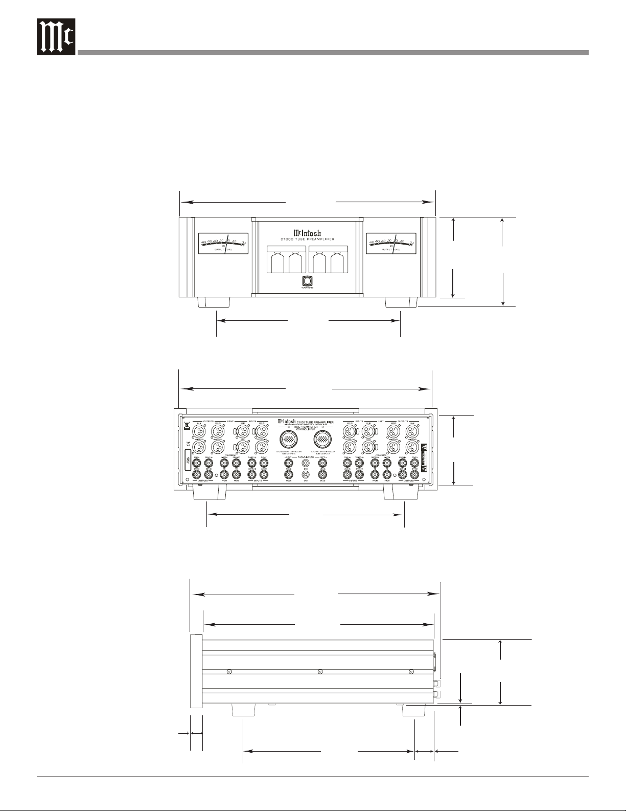
Dimensions
The following dimensions can assist in determining the best
location for the C1000 Controller, C1000 Preamplifier and
C1000 Tube Preamplifier. There is additional information
on page 8 pertaining to installing the C1000 System into
cabinets.
17-
1/2
44.45cm
"
Front View
of the
C1000C
Rear View
of the
C1000C
12-
1/4
31.12cm
17"
43.18cm
13-
1/4
33.65cm
5/16
5-
13.49cm
"
6"
15.24cm
"
4-
5/8
"
11.75cm
"
18-
3/4
"
47.63cm
17-
1/8
43.50cm
12-
32.07cm
"
3/16
"
5/8
0.48cm
"
1-
7/16
3.65cm
4-
13/16
12.22cm
"
"
"
1/4
0.64cm
Side View
of the
C1000C
15/16
"
2.38cm
6
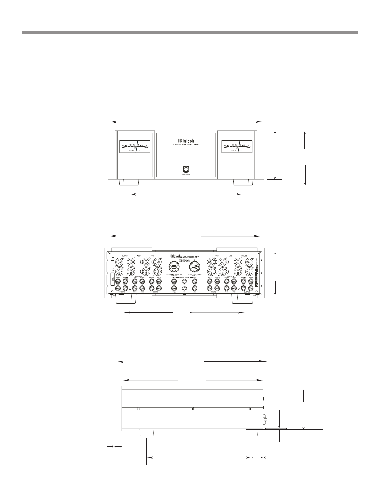
17-1/2"
44.45cm
Dimensions
Front View
of the
C1000P
Rear View
of the
C1000P
12-1/4"
31.12cm
17"
43.18cm
13-1/4"
33.65cm
5/16"
5-
13.49cm
4-5/8"
11.75cm
6"
15.24cm
Side View
of the
C1000P
15/16
2.38cm
18-3/4"
47.63cm
17-1/8"
43.50cm
"
3/16
0.48cm
4-13/16"
12.22cm
"
12-5/8"
32.07cm
1-7/16"
3.65cm
7
17-
1/2
44.45cm
Dimensions, con’t
"
Front View
of the
C1000T
Rear View
of the
C1000T
12-
1/4
31.12cm
17"
43.18cm
13-
1/4
"
33.65cm
5/16
5-
13.49cm
"
6"
15.24cm
"
4-
5/8
"
11.75cm
18-
3/4
"
47.63cm
17-
1/8
"
43.50cm
"
Side View
of the
3/16
0.48cm
4-
13/16
12.22cm
"
C1000T
15/16
"
2.38cm
8
12-
5/8
32.07cm
"
1-
7/16
3.65cm
"
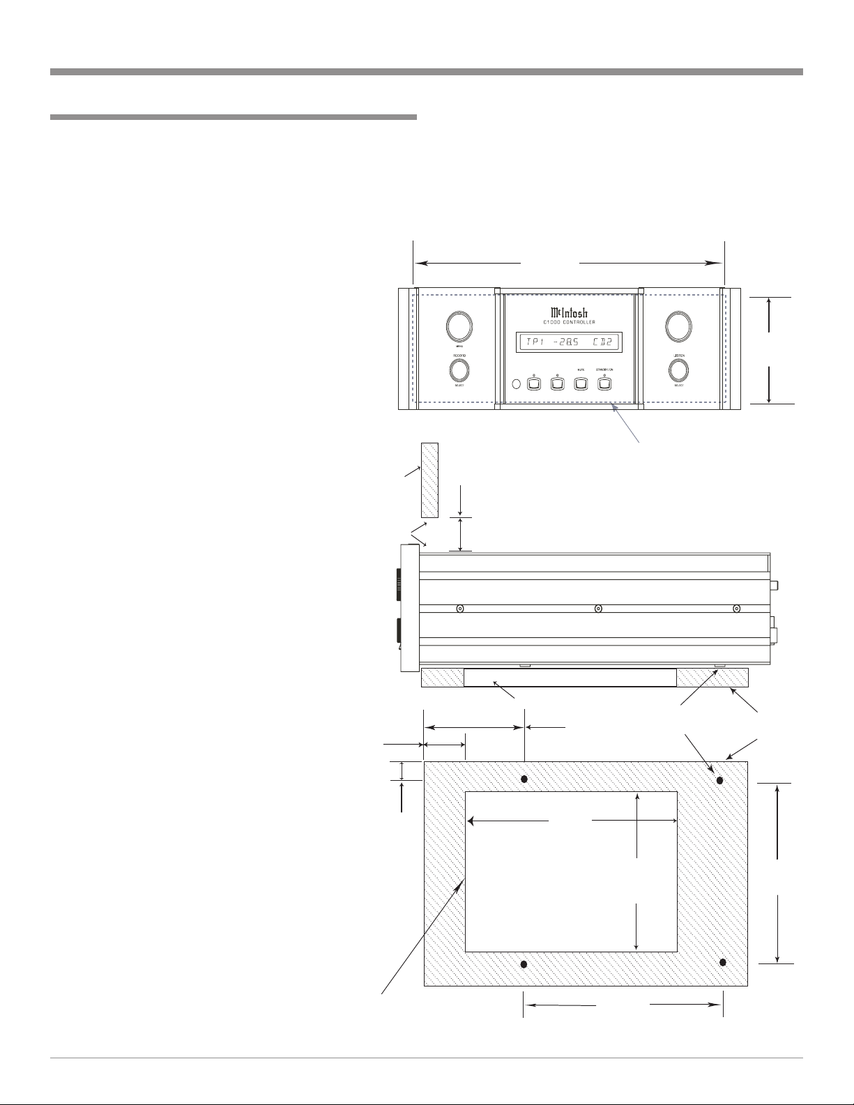
Installation
The C1000C, C1000P and C1000T can be placed upright
on a table or shelf, standing on their four feet. The four feet,
may be removed from the bottom of the C1000C, C1000P
and C1000T when they are custom installed as outlined below. The four feet, together with the mounting screws
should be retained for possible future use if the C1000C,
C1000P and C1000T are removed
from the custom installation and
used free standing. They also can
be custom installed in a piece of
furniture or cabinet of your choice.
The required panel cutout, ventilation cutout and unit dimensions are
shown.
Always provide adequate ventilation for the C1000C, C1000P
and C1000T. Cool operation ensures the longest possible operating life for any electronic instrument. Do not install the units directly above a heat generating
component such as a high powered
amplifier. If all the components are
installed in a single cabinet, a quiet
running ventilation fan can be a
definite asset in maintaining all the
system components at the coolest
possible operating temperature.
A custom cabinet installation
should provide the following minimum spacing dimensions for cool
operation (refer to the illustration
on the next page). Allow at least 2
inches (5.08 cm) above the top of
the C1000C, C1000P and
C1000T, 2 inches (5.08cm) below
the bottom and 1 inch (2.54 cm) on
each side of the Controller/Preamplifier, so that airflow is not obstructed. Allow 24 inches (61.0cm)
depth behind the front panel1 for
Interconnect Cables. Allow 1 inch
(2.54 cm) in front of the mounting
panel for clearance. When the
C1000C, C1000P and C1000T are
to be installed in custom cabinets
refer to illustrations to the right.
C1000C
C1000P
C1000T
Front Panel
Custom Cabinet
Cutout
Cabinet
Front
Panel
Opening for
Ventilation
C1000C
C1000P
C1000T
Side View in a
Partially Open
Custom Cabinet
1-
1/8
"
2.86cm
15/16
C1000C
2.38cm
C1000P
C1000T
Support Shelf in
Custom Cabinet
Notes: Center the Cutout Horizontally on the unit.
For purposes of clarity, the above
illustration is not drawn to scale.
Installation
Be sure to cut out a ventilation hole in the mounting shelf
according to the dimensions in the drawing.
1
Interconnect Cables are supplied with the C1000P
and C1000T Preamplifiers and connect to the
C1000C Controller.
17-
1/16
"
43.34cm
2"
5.08cm
"
Cutout Opening for Custom Mounting
Cutout Opening for Ventilation
5-
13.02cm
14
-3/4
37.47cm
Cutout
Opening
for
Ventilation
1/8
"
"
9-
24.13cm
Chassis
Spacers
14-
1/4
"
36.20cm
1/2
"
4 -
7/8
"
12.38cm
Support
Shelf
15"
38.10cm
9
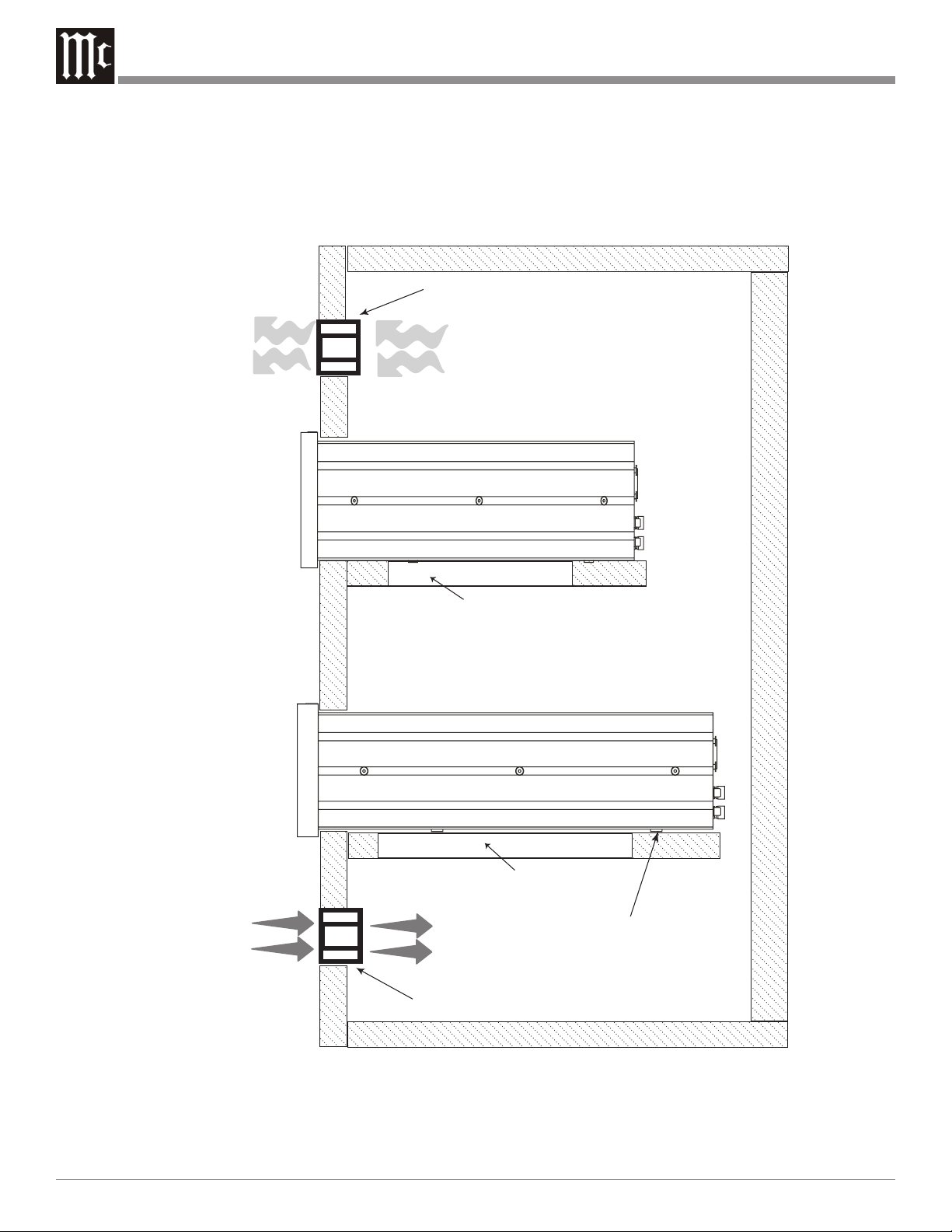
Warm Air
Output
Additional
Component
in Enclosed
Custom
Cabinet
Installation, con’t
Enclosed Custom Cabinet
Ventilaton Fan
C1000C
C1000P
C1000T
Side View
in Enclosed
Custom
Cabinet
Cool Air
Input
Cutout Opening for Ventilation
Cutout Opening for Ventilation
Chassis
Spacers
Ventilaton Fan
10
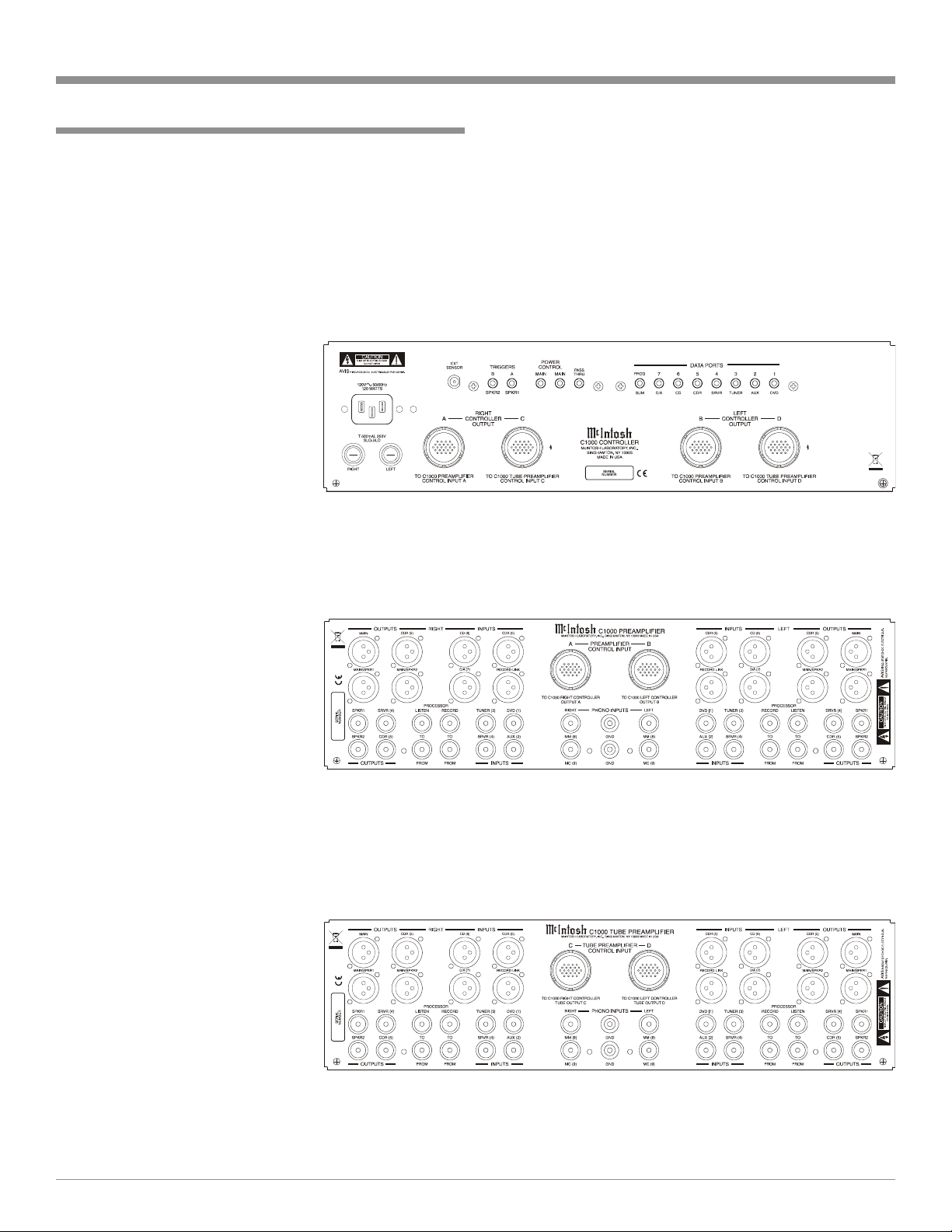
Rear Panel Connections
The identification of Rear Panel Connections for the C1000
Controller, C1000 Preamplifier and C1000 Tube Preamplifier are located on separate folded sheets contained in the
Owner’s Manual Packet.
C1000 Controller
Refer to folded sheet “Mc1A”
C1000 Controller Rear Panel
Connections
Rear Panel Connections
C1000 Preamplifier
Refer to folded sheet “Mc2A”
C1000 Preamplifier Rear
Panel Connections
C1000 Tube Preamplifier
Refer to folded sheet “Mc2B”
C1000 Tube Preamplifier Rear
Panel Connections
11

How to connect the C1000C and C1000P
This page contains information for connecting the McIntosh
C1000C to the C1000P and to other audio components.
The C1000 has the ability to automatically switch power
On/Off to McIntosh Source Components via the Power
Control Connections. The Data Port Connections allow for
the remote operation of basic functions using the C1000 Remote Control. With an external sensor connected to the
C1000, remote control operation of the system is possible
from another room and/or when the C1000 is located in a
cabinet with the doors closed.
The connection instructions below, together with the Input
and Output Connection Diagrams located on the separate
folded sheet “Mc3A/3B”, is an example of a typical audio
system. Your system may vary from this, however the actual
components would be connected in a similar manner.
For additional information refer to “Connector and Cable
Information” on page 4.
Notes: 1. Refer to page 14 for connecting the C1000C with
the C1000T or page 16 for connecting the
C1000C with both the C1000P and C1000T.
2. Balanced and Unbalanced Inputs and Outputs can
be mixed. For example, you may connect signal
sources to Unbalanced Inputs and send signals
out from the Balanced Outputs. You can also use
Balanced and Unbalanced outputs simultaneously,
connected to different power amplifiers.
3. With the addition of a McIntosh Power Controller
and Remote Control Translator connected to the
C1000, any McIntosh Classic Components and/or
non McIntosh Components connected to the
C1000 can be operated more conveniently.
Contact your McIntosh Dealer for additional
information.
Power Control Connections:
1. Connect one of the supplied custom 21Conductor
Cables from the C1000C RIGHT CONTROLLER
OUTPUT A Socket to the C1000P TO PREAMPLIFIER CONTROL INPUT A Socket.
Note: After the cable connector is firmly seated into the
chassis socket, rotate the locking collar clockwise
until it is finger tight.
2. In a similar manner, connect the other 21 Conductor
Cable from the C1000C Socket B to Socket B on the
C1000P.
3. Connect a Cable from the C1000C POWER CONTROL MAIN Jack to the Power Control In Jack on the
McIntosh Right Channel Power Amplifier and another
Control Cable from the McIntosh Right Channel Power
Amplifier Power Control Out Jack to the McIntosh
Right Channel Power Amplifier Power Control In Jack.
Note: There is approximately a one-half second delay
added to the Power Control Out Jack signal going
to the next McIntosh Power Amplifier, to reduce
the strain on the AC Power Line.
4. Connect a Cable from the other C1000C POWER
CONTROL MAIN Jack to the Power Control In of the
McIntosh D/A Converter.
5. Connect a Cable from the McIntosh D/A Converter
Power Control Out Jack to the Power Control In of a
McIntosh AM/FM Tuner.
6. Connect a Cable from the McIntosh AM/FM Tuner
Control Out Jack to the Power Control In of a McIntosh
Audio/Video Player.
7. Connect any remaining McIntosh Source Components
in a similar manner.
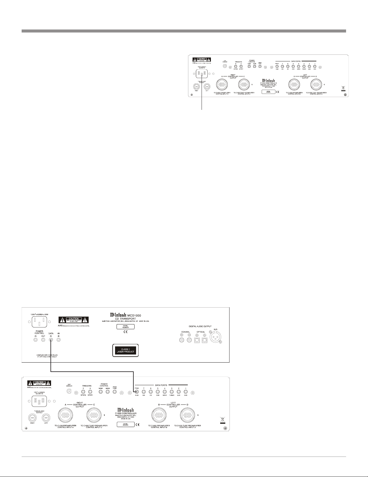
Data Control Connections:
8. Connect a Cable from the C1000C D/A (7) DATA
PORT to the Data In Jack of the McIntosh MDA1000
D/A Converter.
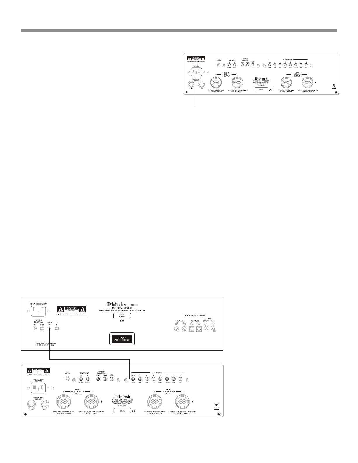
Note: If a McIntosh MCD1000 is part of the system,
connect the SUM DATA PORT Jack to the Data
Port In Jack on the MCD1000, using a Data
Cable. Refer to figure A.
9. Connect a Cable from the C1000C TUNER (3) DATA
PORT to the Data In Jack of the McIntosh Tuner.
10. Connect a Cable from the C1000C DVD (1) DATA
PORT to the Data In Jack of the McIntosh Audio/Video
Player.
11. Connect any remaining McIntosh Source Components in
a similar manner.
12. Optionally connect a RG-59 or RG-6 Cable from the
C1000C Rear Panel EXT Sensor connector to the
McIntosh Sensor.
Audio Connections:
13. Connect XLR Cables from the McIntosh D/A Converter
to the C1000 Preamplifier Balanced XLR D/A (7)
LEFT and RIGHT INPUTS.
14. Connect Cables from the McIntosh Tuner Fixed Audio
Outputs to the C1000 Preamplifier Unbalanced
TUNER (3) LEFT and RIGHT INPUTS.
15. Connect Cables from the McIntosh Audio/Video Player
2CH Unbalanced Audio Outputs to the C1000 Preamplifier Unbalanced DVD (1) LEFT and RIGHT INPUTS.
Note: The 2CH Balanced Audio Outputs of the McIntosh
Audio/Video Player may be connected to the
C1000 Preamplifier CD (6) INPUTS instead of the
Unbalanced Connections.
12
16. Connect Cables from the Turntable (with a Moving
Magnet Cartridge) to the C1000 Preamplifier Unbalanced MM (8) LEFT and RIGHT INPUTS.
Note: If the Turntable has a Moving Coil Cartridge,
connect the cables to the MC (9) Inputs.
17. Connect the Turntable Ground Cable to the GND binding post located between the C1000 Preamplifier MM
(8) LEFT and RIGHT INPUTS.
18. Connect Cables from the External Sound Processor Left
and Right Inputs to the C1000 Preamplifier PROCESSOR TO LEFT and RIGHT Output Jacks.
19. Connect Cables from the External Sound Processor Left
and Right Outputs to the C1000 Preamplifier PROCESSOR FROM LEFT and RIGHT Input Jacks.
20. Connect Cables from the Music Server Left and Right
Outputs to the C1000 Preamplifier Unbalanced SRVR
(4) LEFT and RIGHT INPUTS Jacks.
21. Connect Cables from the Music Server Left and Right
Inputs to the C1000 Preamplifier Unbalanced SRVR (4)
LEFT and RIGHT OUTPUTS Jacks.
22. Connect XLR Cables from the C1000 Preamplifier
MAIN LEFT and RIGHT Balanced OUTPUTS, to one
of the Balanced Inputs on the Left and Right McIntosh
Power Amplifiers.
Note: If the C1000 is part of a Multichannel Audio
System, proceed to page 19 at this time.
23. Connect the supplied AC Power Cord between C1000C
AC Power Cord Socket and a live AC outlet. Refer to
figure B.
24. Proceed to page 23 for customizing the SETUP Features of the C1000 Preamplifier.
How to connect the C1000C and C1000P
Figure B
Connect
Figure A
13

How to connect the C1000C and C1000T
This page contains information for connecting the McIntosh
C1000C to the C1000T and to other audio components.
The C1000 has the ability to automatically switch power
On/Off to McIntosh Source Components via the Power
Control Connections. The Data Port Connections allow for
the remote operation of basic functions using the C1000 Remote Control. With an external sensor connected to the
C1000, remote control operation of the system is possible
from another room and/or when the C1000 is located in a
cabinet with the doors closed.
The connection instructions below, together with the Input
and Output Connection Diagrams located on the separate
folded sheet “Mc4A/4B”, is an example of a typical audio
system. Your system may vary from this, however the actual
components would be connected in a similar manner.
For additional information refer to “Connector and Cable
Information” on page 4.
Notes: 1. Refer to page 12 for connecting the C1000C with
the C1000P or page 16 for connecting the
C1000C with both the C1000P and C1000T.
2. Balanced and Unbalanced Inputs and Outputs can
be mixed. For example, you may connect signal
sources to Unbalanced Inputs and send signals
out from the Balanced Outputs. You can also use
Balanced and Unbalanced outputs simultaneously,
connected to different power amplifiers.
3. With the addition of a McIntosh Power Controller
and Remote Control Translator connected to the
C1000, any McIntosh Classic Components and/or
non McIntosh Components connected to the
C1000 can be operated more conveniently.
Contact your McIntosh Dealer for additional
information.
Power Control Connections:
1. Connect one of the supplied custom 21Conductor
Cables from the C1000C RIGHT CONTROLLER
OUTPUT C Socket to the C1000T TO TUBE
PREAMPLIFIER CONTROL INPUT C Socket.
Note: After the cable connector is firmly seated into the
chassis socket, rotate the locking collar clockwise
until it is finger tight.
2. In a similar manner, connect the other 21 Conductor
Cable from the C1000C Socket D to Socket D on the
C1000T.
3. Connect a Cable from the C1000C POWER CONTROL MAIN Jack to the Power Control In Jack on the
McIntosh Right Channel Power Amplifier and another
Control Cable from the McIntosh Right Channel Power
Amplifier Power Control Out Jack to the McIntosh
Right Channel Power Amplifier Power Control In Jack.
Note: There is approximately a one-half second delay
added to the Power Control Out Jack signal going
to the next McIntosh Power Amplifier, to reduce
the strain on the AC Power Line.
4. Connect a Cable from the other C1000C POWER
CONTROL MAIN Jack to the Power Control In of the
McIntosh D/A Converter.
5. Connect a Cable from the McIntosh D/A Converter
Power Control Out Jack to the Power Control In of a
McIntosh AM/FM Tuner.
6. Connect a Cable from the McIntosh AM/FM Tuner
Control Out Jack to the Power Control In of a McIntosh
Audio/Video Player.
7. Connect any remaining McIntosh Source Components
in a similar manner.
Data Control Connections:
8. Connect a Cable from the C1000C D/A (7) DATA
PORT to the Data In Jack of the McIntosh MDA1000
D/A Converter.
Note: If a McIntosh MCD1000 is part of the system,
connect the SUM DATA PORT Jack to the Data
Port In Jack on the MCD1000, using a Data
Cable. Refer to figure A.
9. Connect a Cable from the C1000C TUNER (3) DATA
PORT to the Data In Jack of the McIntosh Tuner.
10. Connect a Cable from the C1000C DVD (1) DATA
PORT to the Data In Jack of the McIntosh Audio/Video
Player.
11. Connect any remaining McIntosh Source Components in
a similar manner.
12. Optionally connect a RG-59 or RG-6 Cable from the
C1000C Rear Panel EXT Sensor connector to the
McIntosh Sensor.
Audio Connections:
13. Connect XLR Cables from the McIntosh D/A Converter
to the C1000 Tube Preamplifier Balanced XLR D/A (7)
LEFT and RIGHT INPUTS.
14. Connect Cables from the McIntosh Tuner Fixed Audio
Outputs to the C1000 Tube Preamplifier Unbalanced
TUNER (3) LEFT and RIGHT INPUTS.
15. Connect Cables from the McIntosh Audio/Video Player
2CH Unbalanced Audio Outputs to the C1000 Tube
Preamplifier Unbalanced DVD (1) LEFT and RIGHT
INPUTS.
Note: The 2CH Balanced Audio Outputs of the McIntosh
Audio/Video Player may be connected to the
C1000 Tube Preamplifier CD (6) INPUTS instead
of the Unbalanced Connections.
14
16. Connect Cables from the Turntable (with a Moving
Magnet Cartridge) to the C1000 Tube Preamplifier Unbalanced MM (8) LEFT and RIGHT INPUTS.
Note: If the Turntable has a Moving Coil Cartridge,
connect the cables to the MC (9) Inputs.
17. Connect the Turntable Ground Cable to the GND binding post located between the C1000 Tube Preamplifier
MM (8) LEFT and RIGHT INPUTS.
18. Connect Cables from the External Sound Processor Left
and Right Inputs to the C1000 Tube Preamplifier PROCESSOR TO LEFT and RIGHT Output Jacks.
19. Connect Cables from the External Sound Processor Left
and Right Outputs to the C1000 Tube Preamplifier
PROCESSOR FROM LEFT and RIGHT Input Jacks.
20. Connect Cables from the Music Server Left and Right
Outputs to the C1000 Tube Preamplifier Unbalanced
SRVR (4) LEFT and RIGHT INPUTS Jacks.
21. Connect Cables from the Music Server Left and Right
Inputs to the C1000 Tube Preamplifier Unbalanced
SRVR (4) LEFT and RIGHT OUTPUTS Jacks.
22. Connect XLR Cables from the C1000 Tube Preamplifier MAIN LEFT and RIGHT Balanced OUTPUTS, to
one of the Balanced Inputs on the Left and Right McIntosh Power Amplifiers.
Note: If the C1000 is part of a Multichannel Audio
System, proceed to page 19 at this time.
23. Connect the supplied AC Power Cord between C1000C
AC Power Cord Socket and a live AC outlet. Refer to
figure B.
24. Proceed to page 23 for customizing the SETUP Features of the C1000 Tube Preamplifier.
How to connect the C1000C and C1000T
Figure B
Connect
Figure A
15

How to connect the C1000C, C1000P and
C1000T
This page contains information for connecting the McIntosh
C1000C to the C1000P/C1000T and to other audio components.
The C1000 has the ability to automatically switch power
On/Off to McIntosh Source Components via the Power
Control Connections. The Data Port Connections allow for
the remote operation of basic functions using the C1000 Remote Control. With an external sensor connected to the
C1000, remote control operation of the system is possible
from another room and/or when the C1000 is located in a
cabinet with the doors closed.
The connection instructions below, together with the Input
and Output Connection Diagrams located on the separate
folded sheet “Mc5A/5B”, is an example of a typical audio
system. Your system may vary from this, however the actual
components would be connected in a similar manner.
For additional information refer to “Connector and Cable
Information” on page 4.
Notes: 1. Balanced and Unbalanced Inputs and Outputs
can be mixed. For example, you may connect
signal sources to Unbalanced Inputs and send
signals out from the Balanced Outputs. You can
also use Balanced and Unbalanced outputs
simultaneously, connected to different power
amplifiers.
3. With the addition of a McIntosh Power Controller
and Remote Control Translator connected to the
C1000, any McIntosh Classic Components and/or
non McIntosh Components connected to the
C1000 can be operated more conveniently.
Contact your McIntosh Dealer for additional
information.
Power Control Connections:
1. Connect one of the supplied custom 21Conductor
Cables from the C1000C RIGHT CONTROLLER
OUTPUT A Socket to the C1000T TO PREAMPLIFIER CONTROL INPUT A Socket.
Note: After the cable connector is firmly seated into the
chassis socket, rotate the locking collar clockwise
until it is finger tight.
2. In a similar manner, connect a 21 Conductor Cable
from the C1000C Socket B to Socket B on the C1000P.
Also connect a 21 Conductor Cable from the C1000C
Socket C to Socket C on the C1000T and connect the
remaining Cable between C1000C Socket D to Socket
D on the C1000T.
3. Connect a Cable from the C1000C POWER CONTROL MAIN Jack to the Power Control In Jack on the
McIntosh Right Channel Power Amplifier and another
Control Cable from the McIntosh Right Channel Power
How to connect the C1000C, C1000P and C1000T
Amplifier Power Control Out Jack to the McIntosh
Right Channel Power Amplifier Power Control In Jack.
Note: There is approximately a one-half second delay
added to the Power Control Out Jack signal going
to the next McIntosh Power Amplifier, to reduce
the strain on the AC Power Line.
4. Connect a Cable from the other C1000C POWER
CONTROL MAIN Jack to the Power Control In of the
McIntosh D/A Converter.
5. Connect a Cable from the McIntosh D/A Converter
Power Control Out Jack to the Power Control In of a
McIntosh AM/FM Tuner.
6. Connect a Cable from the McIntosh AM/FM Tuner
Control Out Jack to the Power Control In of a McIntosh
Audio/Video Player.
7. Connect any remaining McIntosh Source Components
in a similar manner.
Data Control Connections:
8. Connect a Cable from the C1000C D/A (7) DATA
PORT to the Data In Jack of the McIntosh MDA1000
D/A Converter.
Note: If a McIntosh MCD1000 is part of the system,
connect the SUM DATA PORT Jack to the Data
Port In Jack on the MCD1000, using a Data
Cable. Refer to figure A.
9. Connect a Cable from the C1000C TUNER (3) DATA
PORT to the Data In Jack of the McIntosh Tuner.
10. Connect a Cable from the C1000C DVD (1) DATA
PORT to the Data In Jack of the McIntosh Audio/Video
Player.
11. Connect any remaining McIntosh Source Components in
a similar manner.
12. Optionally connect a RG-59 or RG-6 Cable from the
C1000C Rear Panel EXT Sensor connector to the
McIntosh Sensor.
Audio Connections:
13. Connect XLR Cables from the McIntosh D/A Converter
to the C1000 Preamplifier Balanced XLR D/A (7)
LEFT and RIGHT INPUTS.
14. Connect Cables from the McIntosh Tuner Fixed Audio
Outputs to the C1000 Preamplifier Unbalanced
TUNER (3) LEFT and RIGHT INPUTS.
15. Connect Cables from the McIntosh Audio/Video Player
2CH Unbalanced Audio Outputs to the C1000 Preamplifier Unbalanced DVD (1) LEFT and RIGHT INPUTS.
Note: The 2CH Balanced Audio Outputs of the McIntosh
Audio/Video Player may be connected to the
C1000 Preamplifier CD (6) INPUTS instead of the
Unbalanced Connections.
16
 Loading...