


 Loading...
DiamondMax 10 80/100/120/160/200/250/300GB Serial ATA
February 16, 2006
Part Number: 000001914

©February 16, 2006, Maxtor Corporation. All rights reserved. Printed in U.S.A. This publication could include technical inaccuracies or typographical errors. Changes are periodically made to the information herein – which will be incorporated in revised editions of the publication. Maxtor may make changes or improvements in the product(s) described in this publication at any time and without notice.
UL/CSA/VDE/TUV/RoHS
UL standard 1954 recognition granted under File No. E146611
CSA standard C22.2-950 certification granted under File No. LR49896
TUV Rheinland EN 60 950
Tested to FCC Rules for Radiated and Conducted Emissions, Part 15, Sub Part J, for Class-B Equipment.
Korean EMC certifications are issued by Radio Research laboratory (RPL), which is organized under the Ministry of Information and Communications (MIC). EMC testing includes electromagnetic emissions (EMI) and susceptibility (EMS). Certified equipment is labeled with the MIC mark and certification number.
The DiamondMax 10 product has been tested and found to be in compliance with Korean Radio Research Laboratory (RRL) EMC requirements. The product bears MIC mark/logo with certification number.
DiamondMax 10 model number 6LXXXXX meet the EU directive for the Restriction and Use of Hazardous Substances (RoHS), 2002/95/EC of the European Parliament and the council of 27 January, 2003. DiamondMax 10 model numbers 6BXXXXX do not meet these initiatives.
PATENTS
These products are covered by or licensed under one or more of the following U.S. Patents:
4,419,701; 4, 538,193 4,625,109; 4,639,798; 4,647,769; 4,647,997; 4,661,696; 4,669,004; 4,675,652; 4,703,176; 4,730,321; 4,772,974; 4,783,705; 4,819,153; 4,882,671; 4,920,442; 4,920,434; 4,982,296; 5,005,089; 5,027,241; 5,031,061; 5,084,791; 5,119,254; 5,160,865; 5,170,229; 5,177,771; Other U.S. and Foreign Patents Pending.
Maxtor®, MaxFax® are registered trademarks of Maxtor Corporation, registered in the U.S.A. and other countries. Maxtor DiamondMax 10, AutoTransfer, AutoRead, AutoWrite, DisCache, DiskWare, Defect Free Interface, and WriteCache are trademarks of Maxtor Corporation. All other brand names or trademarks are the property of their manufacturers.
Maxtor reserves the right to make changes and improvements to its products, without incurring any obligation to incorporate such changes or improvements into units previously sold or shipped.
This product or document is protected by copyright and distributed under licences restricting its use, copying, distributing, and decompilation. No part of this product or document may be reproduced in any form by any means without prior written authorization of Maxtor and its licensors, if any.
RESTRICTED RIGHTS LEGEND: Use, duplication, or disclosure by the government is subject to restrictions as set forth in subparagraphs (c)(1)(ii) of the Rights in Technical Data and Computer Software clause at DFARS 252.227-7013 and FAR 52.227-19.
THIS PUBLICATION IS PROVIDED “AS IS” WITHOUT WARRANTY OF ANY KIND, EITHER EXPRESS OR IMPLIED, INCLUDING, BUT NOT LIMITED TO, THE IMPLIED WARRANTIES OF MERCHANTABILITY, FITNESS FOR A PARTIULAR PURPOSE, OR NON-INFRINGE- MENT.
You can request Maxtor publications from your Maxtor Sales Representative or order them directly from Maxtor.
Publication Number: Part Number: 000001914
Corporate Headquarters:
500 McCarthy Blvd.
Milpitas, California 95035
Tel: 408-894-5000
Fax: 408-362-4740
Before You Begin
Thank you for your interest in Maxtor Serial ATA hard disk drives. This manual provides technical information for OEM engineers and systems integrators regarding the installation and use of Maxtor Serial ATA hard drives. Please do not remove or cover up Maxtor factory-installed drive labels. They contain information required should the drive ever need repair. Drive repair should be performed only at an authorized repair center. For repair information, contact the Maxtor Product Support Center at 1-800-2MAXTOR.
CAUTION: Maxtor Serial ATA hard drives are precision products. Failure to follow these precautions and guidelines outlined here may lead to product failure, damage and invalidation of all warranties. Please refer to chapter 3 of this manual for more information on handling instructions.
1BEFORE unpacking or handling a drive, take all proper electrostatic discharge (ESD) precautions, including personnel and equipment grounding. Stand-alone drives are sensitive to ESD damage.
2BEFORE removing drives from their packing material, allow the hard drive to reach room temperature.
3During handling, NEVER drop, jar, or bump a drive.
4Once a drive is removed from the Maxtor shipping container, IMMEDIATELY secure the drive through its mounting holes within a chassis. Otherwise, store the drive flat on a padded, grounded, antistatic surface. NEVER stack hard drives. This may cause damage to the drive.

Table of Contents
Table of Content
Chapter 1
Introduction
1.1 |
MAXTOR CORPORATION ................................................................................ |
1-1 |
1.2 |
AUDIENCE ............................................................................................................. |
1-1 |
1.3 |
MANUAL ORGANIZATION................................................................................ |
1-2 |
1.4 |
TERMINOLOGY AND CONVENTIONS ........................................................... |
1-3 |
1.5 |
REFERENCES.................................. ...................................................................... |
1-4 |
Chapter 2
GENERAL DESCRIPTION
2.1 |
PRODUCT OVERVIEW ....................................................................................... |
2-1 |
2.2 |
KEY FEATURES..................................................................................................... |
2-2 |
2.3 |
REGULATORY COMPLIANCE STANDARDS .................................................. |
2-3 |
2.4 |
HARDWARE REQUIREMENTS ......................................................................... |
2-4 |
Chapter 3
INSTALLATION
3.1 |
SPACE REQUIREMENTS..................................................................................... |
3-1 |
|
3.2 |
UNPACKING INSTRUCTIONS........................................................................... |
3-2 |
|
3.3 |
HARDWARE OPTIONS ....................................................................................... |
3-5 |
|
|
3.3.1 |
ATA Interface Connector ................................................................................. |
3-5 |
|
3.3.2 |
ATA BUS ADAPTER ..................................................................................... |
3-9 |
3.4 |
COMBINATION CONNECTOR (J1)................................................................... |
3-9 |
|
|
3.4.1 DC Power (J1, Section A) .............................................................................. |
3-11 |
|
|
3.4.2 External Drive Activity LED .......................................................................... |
3-11 |
|
|
3.4.3 ATA Bus Interface Connector (J1, Section C) ................................................ |
3-11 |
|
|
3.4.4 SATA (Serial ATA) Interface Connector ........................................................ |
3-12 |
|
|
3.4.5 |
SATA BUS ADAPTER ................................................................................. |
3-12 |
3.5 |
COMBINATION CONNECTOR (J1)................................................................. |
3-13 |
|
|
3.5.1 DC Power (J1, Section A) .............................................................................. |
3-14 |
|
|
3.5.2 ATA Bus Interface Connector (J1, Section C) ................................................ |
3-16 |
|
3.6 |
MOUNTING......................................................................................................... |
3-17 |
|
|
3.6.1 |
Orientation ..................................................................................................... |
3-17 |
|
3.6.2 |
Clearance ....................................................................................................... |
3-19 |
|
3.6.3 |
Ventilation ..................................................................................................... |
3-19 |
3.7 |
Installing the Hard Drive in a Macintosh |
|
|
DiamondMax 10 80/100/120/160/200/250/300GB Serial ATA |
i |

Table of Contents
3.8 FOR SYSTEMS WITH A MOTHERBOARD ATA/SATA ADAPTER................ |
3-20 |
||
3.8 |
FOR SYSTEMS WITH AN ATA ADAPTER BOARD ....................................... |
3-20 |
|
|
3.8.1 |
Adapter Board Installation ............................................................................... |
3-20 |
3.9 |
TECHNIQUES IN DRIVE CONFIGURATION ................................................ |
3-23 |
|
|
3.9.1 |
The 528-Megabytes Barrier ............................................................................ |
3-23 |
|
3.9.2 |
The 8.4-Gigabytes Barrier ............................................................................... |
3-23 |
|
3.9.3 |
Operating system limitations ........................................................................... |
3-24 |
3.10 SYSTEM STARTUP AND OPERATION ........................................................... |
3-24 |
||
Chapter 4
PRODUCT SPECIFICATIONS
4.1 |
Models and Capacities ............................................................................................... |
4-1 |
4.2 |
Drive Configuration .................................................................................................. |
4-1 |
4.3 |
Performance Specifications......................................................................................... |
4-2 |
4.4 |
Physical Dimensions .................................................................................................. |
4-3 |
4.5 |
Power Requirements ................................................................................................. |
4-3 |
4.6 |
Power Mode Definitions ........................................................................................... |
4-4 |
4.7 |
EPA Energy Star Compliance .................................................................................... |
4-4 |
4.8 |
Environmental Limits ................................................................................................ |
4-5 |
4.9 |
Shock and Vibration .................................................................................................. |
4-6 |
4.10 |
Reliability Specifications ............................................................................................ |
4-7 |
4.11 |
EMC/EMI ................................................................................................................ |
4-8 |
4.11.1 Radiated Electromagnetic Field Emissions - EMC Compliance ......................... |
4-8 |
|
4.11.2 Canadian Emissions Statement .......................................................................... |
4-8 |
|
4.12 |
Safety Regulatory Compliance................................................................................... |
4-8 |
Chapter 5
ATA BUS INTERFACE AND ATA COMMANDS
5.1 |
INTRODUCTION ................................................................................................. |
5-1 |
|
5.2 |
MECHANICAL INTERFACE ................................................................................ |
5-1 |
|
|
5.2.1 Signal Cable and Connector .............................................................................. |
5-1 |
|
5.3 |
ELECTRICAL INTERFACE................................................................................... |
5-1 |
|
|
5.3.1 |
ATA Bus Interface ............................................................................................ |
5-1 |
5.4 |
REGISTER ADDRESS DECODING ..................................................................... |
5-2 |
|
5.5 |
COMMAND INTERFACE..................................................................................... |
5-2 |
|
|
5.5.1 |
General Feature Set ........................................................................................... |
5-2 |
|
5.5.2 |
Supported Commands ...................................................................................... |
5-2 |
Chapter 6
SERVICE AND SUPPORT
6.1 Product Support/Technical Assistance/Customer Service .......................................... |
6-1 |
ii DiamondMax 10 80/100/120/160/200/250/300GB Serial ATA

List of Figures
Figure 3-1 |
DiamondMax 10 Serial ATA Hard Drive Dimensions ................................... |
3-1 |
Figure 3-2 |
Single-Pack Shipping Container .................................................................... |
3-3 |
Figure 3-3 |
20-Pack Shipping Container ......................................................................... |
3-4 |
Figure 3-4 |
Data Transfer Rate Jumper Pin Options ........................................................ |
3-5 |
Figure 3-5 |
Serial ATA Interface Connector .................................................................... |
3-5 |
Figure 3-6 |
Mounting Dimensions .................................................................................. |
3-9 |
Figure 3-7 |
Mounting Screw Clearance’s for the DiamondMax 10 SATA Disk Drive |
...3-11 |
Figure 3-8 |
Interface Connections ................................................................................. |
3-11 |
Figure 3-9 |
Attaching the Cables to the Hard Drive ...................................................... |
3-12 |
Figure 3-10 |
Completing the Drive Installation ............................................................... |
3-13 |
DiamondMax 10 80/100/120/160/200/250/300GB Serial ATA i

Table of Contents
List of Tables
Table 3-1 |
Device plug connector pin definition ................................................................... |
3-9 |
Table 3-2 |
Logical Addressing Format................................................................................... |
3-24 |
Table 5-1 |
Supported Commands........................................................................................... |
5-2 |
Table 5-2 |
Identify Drive Command Parameters .................................................................... |
5-5 |
DiamondMax 10 80/100/120/160/200/250/300GB Serial ATA |
v |

Table of Contents
viDiamondMax 10 80/100/120/160/200/250/300GB Serial ATA

Introduction
Chapter 1
Introduction
1.1Maxtor Corporation
Maxtor corporation is one of the world’s largest suppliers of hard disk drive productsproducts that help store the digital world for millions of users. Maxtor products serve a range of markets, including personal and entertainment, small office/home office, mid-sized business and enterprise
Products
Maxtor storage products include drives and accessories for PC’s, workstations, RAID products, enterprise applications, enterprise servers, high-end systems, consumer electronics and personal storage.
Support
Maxtor provides a variety of consumer support options, all designed to make sure the user gets fast, helpful, accurate information to help resolve any difficulties. These options include a broad, searchable knowledge base of FAQ’s, product manuals, installation guides, information on previously resolved problems, software downloads, and contact by phone or E-mail with a support person. For more information, visit
www.maxtor.com/en/support.
1.2Audience
The DiamondMax 10 80/100/120/160/200/250/300GB Serial ATA product manual is intended for several audiences. These audiences include: the end user, installer, developer, consumer electronics and personal computer original equipment manufacturer (CE/PC,OEM),and distributor. The manual provides information about installation, principles of operation, interface command implementation, and maintenance.
The DiamondMax 10 family of drives provide a high-quality, low cost, market leading 100 GB per disk products to serve the consumer and mainstream commercial markets, as well as the consumer electronics market.
DiamondMax 10 80/100/120/160/200/250/300GB Serial ATA 1-1
Introduction
1.3MANUAL ORGANIZATION
This manual is organized into the following chapters:
•Chapter 1 – Introduction
•Chapter 2 – General Description
•Chapter 3 – Installation
•Chapter 4 – Product Specifications
•Chapter 5 – ATA Bus Interface and ATA Commands
•Chapter 6 – Service and Support
•Appendix A – Breaking the 137-Gigabyte Storage Barrier
1.4TERMINOLOGY AND CONVENTIONS
In the Glossary at the back of this manual, you can find definitions for many of the terms used in this manual. In addition, the following abbreviations are used in this manual:
• |
ASIC |
application-specific integrated circuit |
• |
ATA |
advanced technology attachment |
• |
Bels |
sound power units |
• |
bpi |
bits per inch |
• |
DA |
double amplitude(represents pk-pk shaker displacement) |
• |
dB |
decibels |
• |
dBA |
decibels, A weighted |
• |
DPS |
data protection system |
• |
ECC |
error correcting code |
• |
G/RMS |
G root means square |
• |
Kfci |
thousands of flux changes per inch |
• |
Hz |
hertz |
• |
KB |
kilobytes |
• |
LSB |
least significant bit |
• |
mA |
milliamperes |
• |
MB |
megabytes (1 MB = 1,000,000 bytes when referring to disk |
|
|
transfer rates or storage capacities and 1,048,576 bytes in all |
|
|
other cases) |
1-2 DiamondMax 10 80/100/120/160/200/250/300GB Serial ATA

Introduction
• |
Mb/s |
megabits per second |
• |
MB/s |
megabytes per second |
• |
MHz |
megahertz |
• |
ms |
milliseconds |
• |
MSB |
most significant bit |
• |
mV |
millivolts |
• |
ns |
nanoseconds |
• |
PC |
Personal Computer |
• |
SATA |
serial ATA interface |
• |
SPS |
shock protection system |
• |
tpi |
tracks per inch |
• |
µs |
microseconds |
• |
V |
volts |
The typographical and naming conventions used in this manual are listed below. Conventions that are unique to a specific table appear in the notes that follow that table.
Typographical Conventions:
•Names of Bits: Bit names are presented in initial capitals. An example is the Host Software Reset bit.
•Commands: Interface commands are listed in all capitals. An example is WRITE LONG.
•Register Names: Registers are given in this manual with initial capitals. An example is the Alternate Status Register.
•Parameters: Parameters are given as initial capitals when spelled out, and are given as all capitals when abbreviated. Examples are Prefetch Enable (PE), and Cache Enable (CE).
•Hexadecimal Notation: The hexadecimal notation is given in 9-point subscript form. An example is 30H.
•Signal Negation: A signal name that is defined as active low is listed with a minus sign following the signal. An example is RD–.
•Messages: A message that is sent from the drive to the host is listed in all capitals. An example is ILLEGAL COMMAND.
Naming Conventions:
DiamondMax 10 80/100/120/160/200/250/300GB Serial ATA 1-3

Introduction
•Host: In general, the system in which the drive resides is referred to as the host.
•Computer Voice: This refers to items you type at the computer keyboard. These items are listed in 10-point, all capitals, Courier font. An example is FORMAT C:/S.
1.5REFERENCES
For additional information about the ATA interface, refer to the latest revision of the draft standard on the internet at http://www.t13.org/ using the link under “1532D AT attachment-7 with packet interface (ATA/ATAPI)”
Additional information can be found on the Serial ATA working Group site at
http://www.serialata.org. Use the “spec and design guidelines” link
1-4 DiamondMax 10 80/100/120/160/200/250/300GB Serial ATA

General Description
Chapter 2
GENERAL DESCRIPTION
This chapter summarizes the general functions and key features of the DiamondMax 10 80/100/120/160/200/250/300GB Serial ATA hard disk drives, as well as the applicable standards and regulations.
2.1PRODUCT OVERVIEW
Maxtor’s DiamondMax 10 Serial ATA hard disk drives are part of a family of high performance, 1-inch-high hard disk drives manufactured to meet the highest product quality standards.
These hard disk drives use nonremovable, 3 1/2-inch hard disks.
The DiamondMax 10 80/100/120/160/200/250/300GB Serial ATA hard disk drives feature an embedded hard disk drive controller, and use ATA commands to optimize system performance. Because the drive manages media defects and error recovery internally, these operations are fully transparent to the user.
The innovative design of the Maxtor DiamondMax 10 hard disk drives incorporate leading edge technologies with Serial ATA and with transfer speeds up to 150 MB/ second, Advanced Cache Management, Shock Protection System™ (SPS), Data Protection System (DPS) and Quiet Drive Technology (QDT). These enhanced technologies enable Maxtor to produce a family of high-performance, high-reliability drives.
2.2KEY FEATURES
The DiamondMax 10 80/100/120/160/200/250/300GB Serial ATA hard disk drive include the following key features:
General
•Low profile, 1-inch height
•Industry standard 3 1/2-inch form factor
•Emulation of IBM® PC AT® task file register, and all AT fixed disk commands
•Real Time Operating System Compliant
•Thin cables for easy routing and improved cooling
•1 meter cable length for increased design and layout flexibility
•Connectors designed for blind mate and hot plug
DiamondMax 10 80/100/120/160/200/250/300GB Serial ATA |
2-1 |

General Description
•Reduced pin count enables RAID scalability
•Complete software and driver transparent with Serial ATA
•Point-to-Point host to device connection
•Low voltages
•Interface power control features
•East installation/configuration (plug/play, no jumpers, no external terminators)
•Command optimization
•Native command queuing using first party DMA
Performance
•Average seek time of <9.0 ms
•Average rotational latency of 4.18 ms
•Serial ATA interface with transfer speeds up to 150MB per second
•8MB and 16MB (250/300) Cache buffer
•Look-ahead DisCache feature with continuous prefetch and WriteCache write-buffering capabilities
•AutoTask Register update, Multi-block AutoRead, and Multi-block AutoWrite features in a custom ASIC
•Read-on-arrival firmware
•Quadruple-burst ECC, and double burst ECC on-the-fly
•1:1 interleave on read/write operations
•Adaptive cache segmentation
•100% FDB (Fluid Dynamic Bearing Motors)
Reliability
•Automatic retry on read errors
•S.M.A.R.T. 4 (Self-Monitoring, Analysis and Reporting Technology)
•Transparent media defect mapping
•High performance, in-line defective sector skipping
•Reassignment of defective sectors discovered in the field, without reformatting
•Shock Protection System to reduce handling induced failures
•Data Protection System to verify drive integrity
•Quiet Drive Technology (QDT)
2-2 DiamondMax 10 80/100/120/160/200/250/300GB Serial ATA

General Description
Versatility
•Power saving modes
•Downloadable firmware
•Ability to daisy-chain two drives on the interface
2.3REGULATORY COMPLIANCE STANDARDS
Maxtor Corporation’s disk drive products meet all domestic and international product safety regulatory compliance requirements. Maxtor’s disk drive products conform to the following specifically marked Product Safety Standards:
•Underwriters Laboratories (UL) Standard 1950. This certificate is a category certification pertaining to all 3.5-inch series drives models.
•Canadian Standards Association (CSA) Standard C.22.2 No. 1950. This certificate is a category certification pertaining to all 3.5-inch series drives models.
•TUV Rheinland Standard EN60 950. This certificate is a category certification pertaining to all 3.5-inch series drives models.
•The DiamondMax 10 product has been tested and found to be in compliance with Korean Radio Research Laboratory (RRL) EMC requirements. The product bears MIC mark/logo with certification number.
Product EMI/EMS Qualifications:
•CE Mark authorization is granted by TUV Rheinland in compliance with our qualifying under EN 55022:1994 and EN 50082-1:1997.
•C-Tick Mark is an Australian authorization marked noted on Maxtor’s disk drive products. The mark proves conformity to the regulatory compliance document AS/NZS 3548: 1995 and BS EN 55022: 1995.
•Maxtor’s disk drives are designed as a separate subassembly that conforms to the FCC Rules for Radiated and Conducted emissions, Part 15 Subpart J; Class B when installed in a given computer system.
•Approval from Taiwan BSMI. Number: D33019.
DiamondMax 10 80/100/120/160/200/250/300GB Serial ATA |
2-3 |

General Description
2-4 DiamondMax 10 80/100/120/160/200/250/300GB Serial ATA
Installation
Chapter 3
INSTALLATION
This chapter explains how to unpack, configure, mount, and connect the Maxtor DiamondMax 10 80/100/120/160/200/250/300GB Serial ATA hard disk drive prior to operation. It also explains how to start up, format, and operate the drive.
3.1SPACE REQUIREMENTS
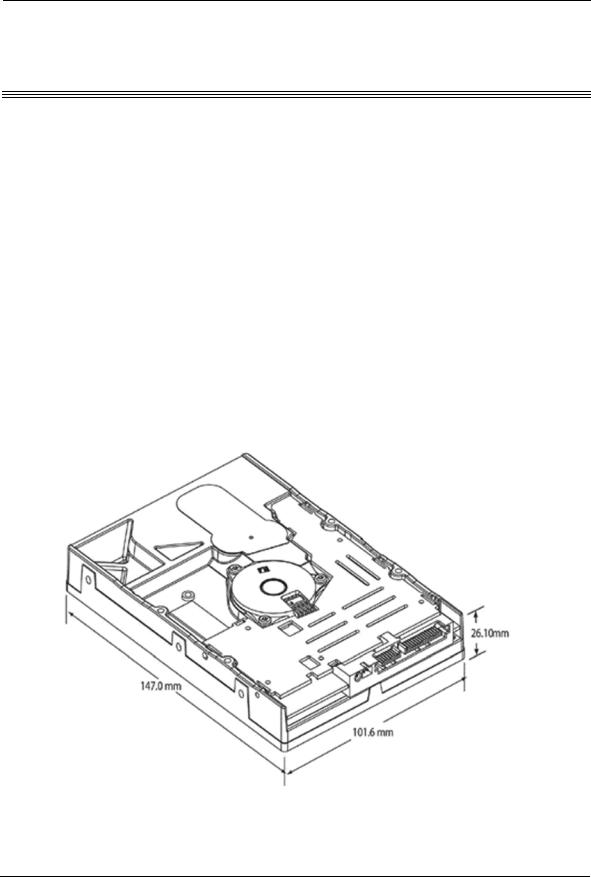
The DiamondMax 10 hard disk drives are shipped without a faceplate. Figure 3-1 shows the external dimensions of the DiamondMax 10 80/100/120/160/200/250/ 300 Serial ATA hard drives. For more information please refer to chapter 4 for product specifications.
Figure 3-1 DiamondMax 10 Serial ATA Hard Drive Dimensions
DiamondMax 10 80/100/120/160/200/250/300GB Serial ATA |
3-1 |

Installation
3.2UNPACKING INSTRUCTIONS
CAUTION: The maximum limits for physical shock can be exceeded if the drive is not handled properly. Special care should be
taken not to bump or drop the drive. It is highly recommended that Maxtor DiamondMax 10 SATA drives are not stacked or placed on any hard surface after they are unpacked. Such handling could cause media damage.
1.Grounded wrist straps should be worn when opening the ESD bag.
2.Three layer runners should be installed on every table and bench where the product is processed while still vulnerable to ESD.
3.Open the shipping container and remove the packing assembly that contains the drive.
4.Remove the drive from the packing assembly.
5.Always handle the disk drive from the sides.
6.Do not touch the circuit board.
7.Never stack the disk drives on top of one another nor store them on their sides.
8.When you are ready to install the drive, remove it from the ESD bag.
CAUTION: During shipment and handling, the antistatic electrostatic discharge (ESD) bag prevents electronic component
damage due to electrostatic discharge. To avoid accidental damage to the drive, do not use a sharp instrument to open the ESD bag and do not touch PCB components.
3-2 DiamondMax 10 80/100/120/160/200/250/300GB Serial ATA
Installation
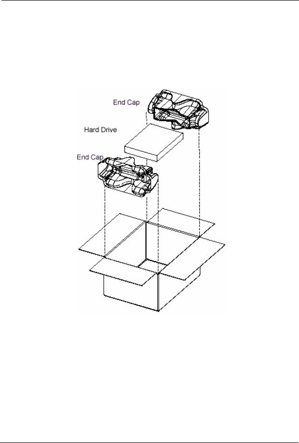
Figure 3-2 shows the shipping container for a single DiamondMax 10 Serial ATA hard disk drive. Figure 3-3 shows the shipping container for a 20 pack of Maxtor DiamondMax 10 Serial ATA hard drives.
Always save the packing materials in case you have to return the product.
Figure 3-2 Single-Pack Shipping Container
DiamondMax 10 80/100/120/160/200/250/300GB Serial ATA |
3-3 |
Installation
Figure 3-3 20-Pack Shipping Container
3.3Hardware Options
3.3.1SATA (Serial ATA) Interface Connector
The Maxtor DiamondMax 10 80/100/120/160/200/250/300GB Serial ATA hard disk drive ships with 2 no connect (NC) pins for the purpose of storing a jumper when not in use. For normal operations, no action is necessary. However, if your motherboard does not support the Gen. II (3Gbps) data rate, you will need to limit the data transfer rate by transferring the jumper to the pins as shown in Figure 3-4.
3-4 DiamondMax 10 80/100/120/160/200/250/300GB Serial ATA

Installation
Figure 3-4 Data Transfer Rate Jumper Pin Options
Figure 3-5 Serial ATA Interface Connector
DiamondMax 10 80/100/120/160/200/250/300GB Serial ATA |
3-5 |

Installation
3.3.2SATA BUS ADAPTER
There are two ways you can configure a system to allow the DiamondMax 10 hard disk drives to communicate over the Serial ATA bus of an IBM or IBM-compatible PC:
1.Connect the drive to a Serial ATA bus connector on the motherboard of the PC.
2.Install an IDE-compatible adapter board in the PC, and connect the drive to the adapter board.
Some PC motherboards have a built in Serial ATA bus connector. These Serial ATA bus connectors are compatible with DiamondMax 10 Serial ATA hard disk drives.If the motherboard has a Serial ATA connector, simply connect a 7 pin Serial ATA cable between the drive and the motherboard.
3.3.3Adapter Board
If your PC motherboard does not contain a built-in Serial ATA bus interface connector, you must install a Serial ATA bus adapter board and connecting cable to allow the drive to interface with the motherboard. Maxtor does not supply such an adapter board, but they are available from several third-party vendors.
Please carefully read the instruction manual that comes with your adapter board to ensure signal compatibility between the adapter board and the drive. Also, make sure that the adapter board jumper settings are appropriate.
3-6 DiamondMax 10 80/100/120/160/200/250/300GB Serial ATA
Loading...