

Page 1

MAXDA T A PLA TINUM
Server Case
Users’ Manual
Page 2

2
Page 3

Contents
1 Chassis Description.........................................................................................7
What Your Kit Includes............................................................................................................. 7
Feature Summary .................................................................................................................... 8
System Components...............................................................................................................8
Chassis Front Panel and Peripheral Bays ............................................................................ 9
Front Panel RJ-45 Serial Connector .................................................................................... 9
Chassis Back I/O Ports and Features .................................................................................10
Front Panel Controls and Indicators ...................................................................................11
Peripherals............................................................................................................................. 13
Hot Swappable SCSI Hard Drives ..................................................................................... 13
Flex Bay............................................................................................................................. 14
Power Supply......................................................................................................................... 14
System Cooling...................................................................................................................... 14
Chassis Security .................................................................................................................... 14
Locking and Unlocking the Front Bezel ............................................................................. 14
2 Assembling the System................................................................................15
Before Y ou Begin ................................................................................................................... 15
Supplies Needed............................................................................................................... 15
Installation/Assembly Safety Instructions.............................................................................. 15
Use Only for Intended Applications .................................................................................. 15
Checking the Power Cord ................................................................................................. 16
Warnings and Cautions.......................................................................................................... 16
WARNING / Before You Remove the Access cover .......................................................... 16
Preparing the Chassis............................................................................................................ 18
Removing the Cover ......................................................................................................... 18
Installing System Components.............................................................................................. 19
Overview of System Components.................................................................................... 19
Removing the Riser Cards ................................................................................................ 20
Removing the Fan Assembly ............................................................................................ 21
Installing Components ...................................................................................................... 21
Installing the Server Board................................................................................................ 22
Routing Cables ...................................................................................................................... 23
Installing the Fan Assembly................................................................................................... 24
Installing the Power Cord and Strain Relief Strap.................................................................. 26
Adding Components to the Server Board.............................................................................. 26
Installing Peripherals.............................................................................................................. 27
Installing a PCI Card on a Riser Card ................................................................................ 27
Installing a Riser Card on the Server Board ...................................................................... 28
3 Installing the System in a Rack....................................................................29
Equipment Rack Precautions................................................................................................. 29
4 Working Inside Your Server...........................................................................31
Tools and Supplies Needed ................................................................................................... 31
Safety: Before You Remove the Cover................................................................................... 31
Warnings and Cautions.......................................................................................................... 31
Lithium Battery Replacement ................................................................................................ 31
MAXDATA PLATINUM Server Manual
3
Page 4

Replacing Components ......................................................................................................... 32
Replacing a Hard Drive...................................................................................................... 32
Replacing a CD-ROM Drive/FDD Module ......................................................................... 34
Replacing a PCI Add-in Card.............................................................................................. 35
Replacing a Power Supply Module.................................................................................... 36
Replacing a Power Supply Cage........................................................................................ 36
Replacing a Fan.................................................................................................................38
Replacing a Backplane Board ............................................................................................ 40
Replacing a Front Panel Board .......................................................................................... 41
Replacing a Server Board.................................................................................................. 41
A Regulatory and Certification Information ...................................................43
Product Regulatory Compliance ............................................................................................ 43
Product Saf ety Compliance............................................................................................... 43
Product EMC Compliance................................................................................................. 43
Electromagnetic Compatibility Notices ................................................................................. 44
FCC Verification Statement (USA)..................................................................................... 44
Europe (CE Declaration of Conformity)............................................................................. 44
B Safety W arnings.............................................................................................45
WARNING: English (US)........................................................................................................ 46
4
Contents
Page 5

Figures
1. System components ...................................................................................................... 8
2. Chassis Front.................................................................................................................. 9
3. Chassis Back .................................................................................................................10
4. Controls and Indicators .................................................................................................11
5. Peripherals.................................................................................................................... 13
6. Removing the Cover..................................................................................................... 18
7. Overview of System Components ............................................................................... 19
8. Removing a Riser Card................................................................................................. 20
9. Removing the Fan Assembly........................................................................................ 21
10. Mounting the Server Board SCB2................................................................................ 22
11. Cable Routing............................................................................................................... 23
12. Floppy/FP/IDE Cable Caution........................................................................................ 24
13. Installing the Fan Assembly ......................................................................................... 25
14. Connecting Fans to the Server Board .......................................................................... 25
15. Installing the Power Cord and Strain Relief Strap......................................................... 26
16. Installing a PCI Card in a Riser Card ............................................................................. 27
17. Installing a Riser Card on the Server Board.................................................................. 28
18. Removing a Carrier and Hard Drive from a Drive Bay................................................... 33
19. Removing a Hard Drive from a Carrier.......................................................................... 33
20. Installing a CD-ROM Drive/FDD Module...................................................................... 34
21. Removing a Riser Card................................................................................................. 35
22. Replacing a Power Supply Module............................................................................... 36
23. Replacing a Power Supply Cage................................................................................... 37
24. Removing the Fan Assembly........................................................................................ 38
25. Removing a Fan............................................................................................................ 39
26. Replacing a Backplane Board ....................................................................................... 40
28. Removing the Server Board ......................................................................................... 42
Tables
1. Control Button Functions.............................................................................................. 12
2. LED Indicator Status .................................................................................................... 12
MAXDATA PLATINUM Server Manual
5
Page 6

6
Page 7

1 Chassis Description
Your MAXDA T A PLA TINUM 2200R server chassis kit is designed to support the Intel® Server
Board and comes with the front panel board, backplane board, power supply, one 3.5-inch
peripheral drive carrier , and six hard driv e carriers installed. T he fan assembly and riser cards
are installed for shipment, but you must remove and reinstall them when you install the
server board.
To complete the system, you must purchase some items separately (see below).
What Your Kit Includes
Your kit includes the following components:
• 2U rack-mount chassis featuring:
– Six hard drive bays with carriers and drive blanks (baffles)
– One bay for an optional CD-ROM drive/FDD module (comes with filler panel and plug)
– One bay for optional tape drive (comes with carrier and filler panel)
• One 350W SSI PFC non-redundant power supply
• Two PCI riser cards for use with the Intel
®
Server Board
• Two system fans
• One internal USB cable, (connecting server board to front panel board)
• One internal flex circuit cable, 100-pin (connecting server board to backplane board)
• One internal SCSI cable (connecting server board to backplane board)
• One internal front panel cable, 34-pin (connecting front panel board to backplane board)
• One Resource CD-ROM containing drivers, utilities, and product guide
• Mounting screws (server board)
• Front, mid, or 4-post rack mounting kit
MAXDATA PLATINUM Server Manual
7
Page 8
Feature Summary
System Components
C
B
A
D
E
F
G
H
I
J
K
L
O
M
N
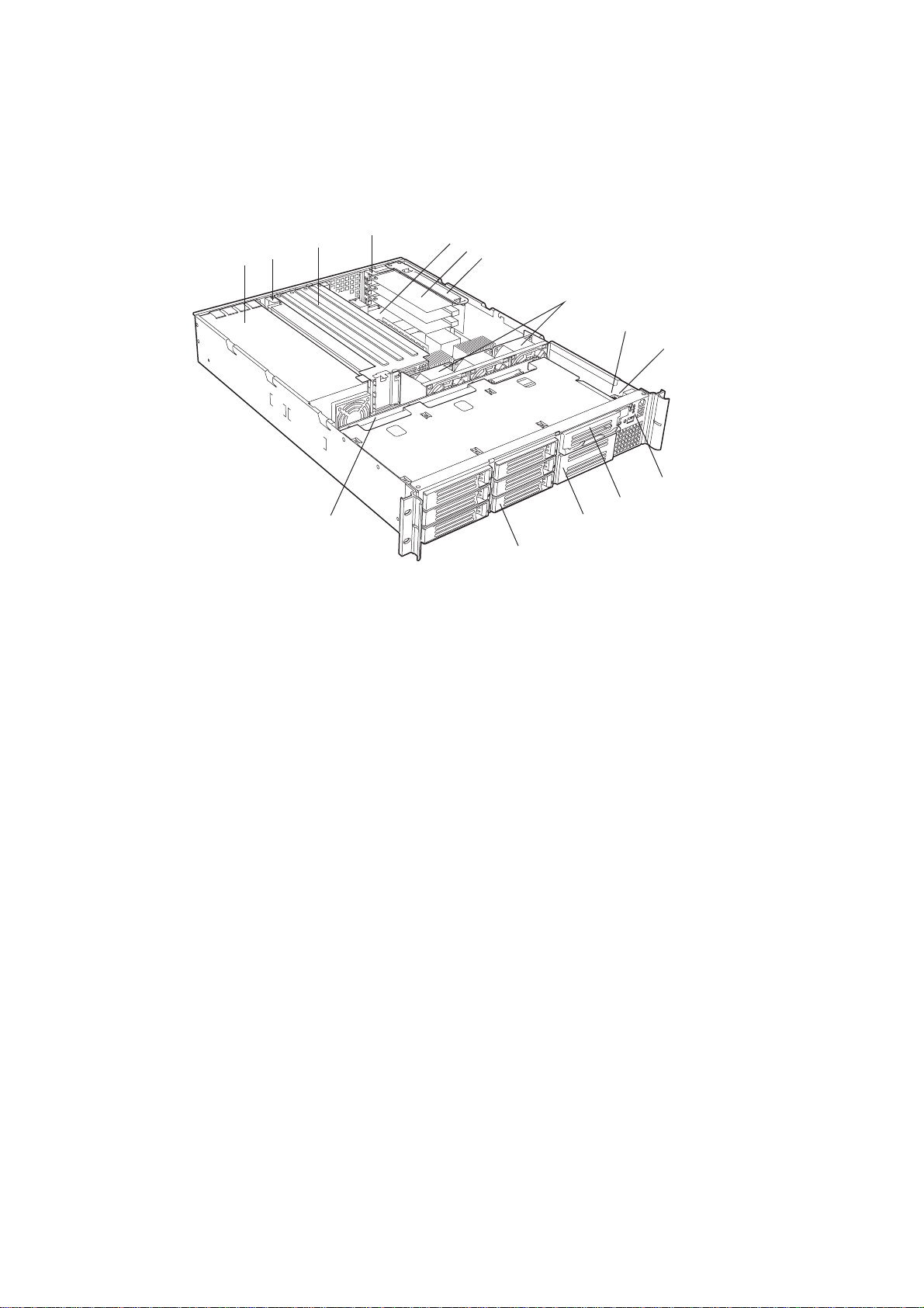
Figure 1. System components
A. Power supply
B. PCI card bracket (full-length)
C. Riser card assembly (full-length)
D. PCI card bracket (low-profile)
E. Server board (accessory to system)
F. PCI add-in card (accessory to system)
G. Riser card assembly (low-profile)
H. System fans
I. Front panel board
J. Intrusion switch
K. Control panel
L. Flex bay (optional CD-ROM drive/FDD module available)
M. Tape drive bay (tape drive available from others)
N. Hard drive bay (one of six, accessory to system)
O. Backplane board
8
Chassis Description
Page 9
Chassis Front Panel and Peripheral Bays
To access the system controls and peripherals when a front bezel is installed, grasp the
bezel and gently pull it towards you until it unsnaps from the chassis.
A
B
C
D
F
E
I
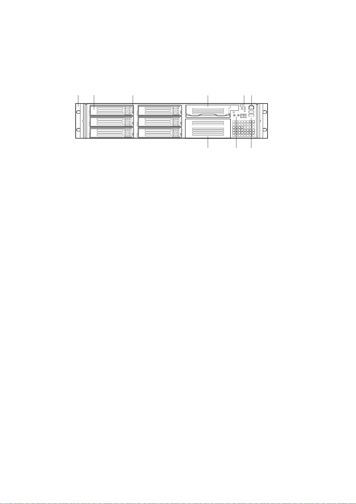
Figure 2. Chassis Front
A. Chassis handles (2)
B. Drive bay (1-inch)
C. HDD activity/fault Indicator
D. Flex bay (optional CD-ROM drive/FDD module available)
E. Front panel indicator lights
F. RJ45 serial port
G. USB connectors 3 and 4
H. System controls
I. Tape drive bay (tape drive available from others)
H
G
Front Panel RJ-45 Serial Connector
Your MAXDATA PLATINUM 2200R server chassis comes equipped with a front panel
accessed server management port (see Figure 2, F). This port is designed to allow PC-to-PC
communication to aid in diagnosing system failures.
MAXDATA PLATINUM Server Manual
9
Page 10
Chassis Back I/O Ports and Features
A
O
N
M
C
B
I
J
L
K
D
H
E
F
G
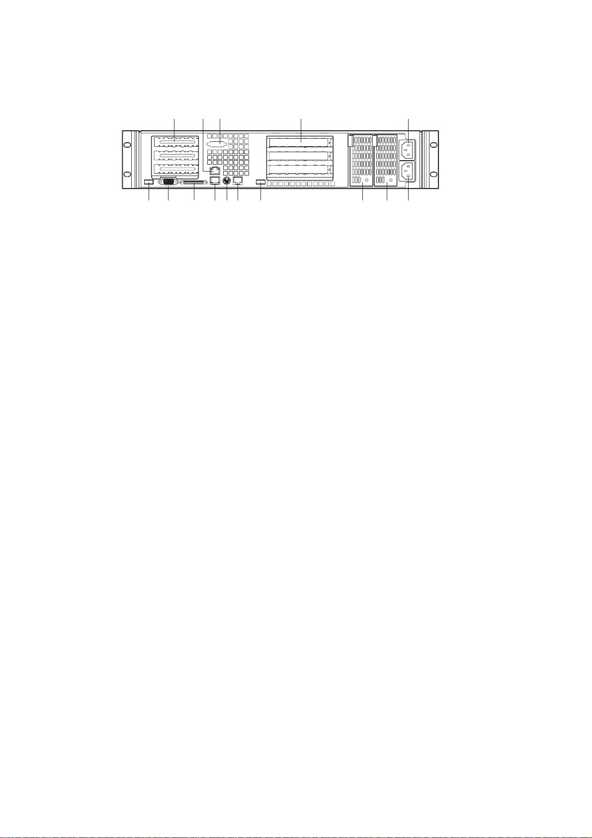
Figure 3. Chassis Back
A. PCI card bracket (low profile)
B. RJ-45 NIC 2 connector Green Status LED/Yellow Status LED
C. COM-1 port mounting hole (cable provided and installed by others)
D. PCI card bracket (full-height)
E. AC power input (primary)
F. AC power input (redundant)
G. Power supply module, redundant (system accessory)
H. Power supply module, primary
I. USB connector 2
J. RJ-45 serial port
K. PS/2Ü mouse/keyboard connector
L. RJ-45 NIC 1 connector
M. SCSI connector (If available)
N. Video connector
O. USB connector 1
10
Chassis Description
Page 11
Front Panel Controls and Indicators
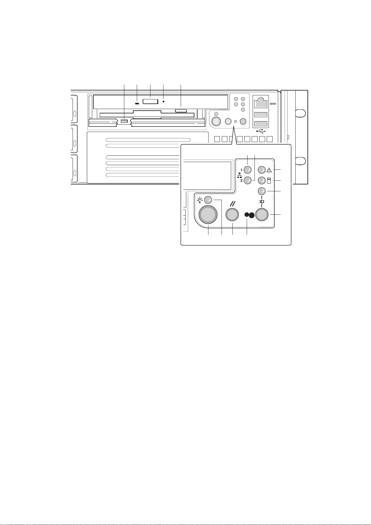
Shown with optional CD-ROM drive/floppy disk drive installed.
K ML N O
A B
C
D
E
F
J H GI
Figure 4. Controls and Indicators
A. NIC 1 ativity LED
B. NIC 2 ativity LED
C. System status LED
D. Fixed diskdrive status LED
E. ID LED
F. ID button
G. NMI button (tool assited)
H. Reset button
I. Power/sleep LED
J. Power button
K. FDD actuvity LED
L. CD-ROM activity LED
M. CD-ROM drive eject button
N. (Tool assisted) Manual CDROM drive eject button
O. FDD eject button
MAXDATA PLATINUM Server Manual
11
Page 12

Table 1. Control Button Functions
nottubpeelS/rewoP
nottubteseR .metsysehtsezilaitinidnastoobeR
nottubIMN
nottubDI
.smetsys
Table 2. LED Indicator Status
DELpeels/rewoP
DELsutatsmetsyS
gnitarepotnailpmocIPCArofnottubpeelsrO.ffo/norewopmetsysehtselggoT
tpurretnielbaksam-nonaseussinipropilcrepapahtiwnottubdessecerehtgnisserP
.sesoprupcitsongaidrofetatstlahanirevresehtstupdna
DIdraobesabehT.DELDIdraobesabehtdnaDELDIlenaptnorfehtffo/noselggoT
revresehtetacolotuoyswolladnasissahcehtforaerehthguorhtelbisivsiDEL
.srevresfokcaradnihebmorfnognikrower'uoy
otdeilpparewopsahmetsysehtsetacidnithgilneergsuounitnoC
oN.gnipeelssimetsysehtsetacidni)4etoN(thgilneerggniknilB.ti
rehto(tiotdeilpparewopevahtonseodmetsysehtsetacidnithgil
.)rewopybdnatsV5naht
DELytivitca2CINDELytivitca1CIN
.detcennocsitihcihwotkrowteneht
gnitareposimetsysehtsetacidnithgilneergsuounitnoC
.potsmetsys/TSOPsetacidnithgil
dnametsysehtneewtebytivitcasetacidnithgilneergsuounitnoC
anignitareposimetsysehtsetacidnithgilneerggniknilB.yllamron
ehtsetacidni)1etoN(thgilrebmasuounitnoC.noitidnocdedarged
rebmagniknilB.noitidnocelbarevocernonrolacitircanisimetsys
oN.noitidnoclacitirc-nonanisimetsysehtsetacidni)1etoN(thgil
ISCS(ytivitcaevirdksiddexifsetacidnithgilneerggniknilbmodnaR
DELsutatsevirdksiddexiF
.)EDIroISCS(tluafronytivitca
DELDI
.desserpedtonsinottubDIsetacidni
evirdksiddexifsetacidni)2etoN(thgilrebmasuounitnoC.)EDIro
evirdksiddexifonsetacidni)3etoN(thgiloN.)EDIroISCS(tluaf
thgiloN.desserpedsinottubDIsetacidnithgileulbsuounitnoC
Notes:
1. The Amber status takes precedence o ver the Green status. When the Amber LED is on
or blinking, the Green LED is off.
2. In order for a hard disk fault indication to occur , either an Intelligent Platf orm Management
Interface (IPMI) based satellite management controller must send a Set Fault Indication
command to the Baseboard Management Controller (BMC), or the system board must
be used with the 2U MAXDATA PLATINUM 2200R hot swappable backplane.
3. Also off when the system is powered off or in a sleep state.
4. The Power LED sleep indication is maintained on standby b y the chipset. If the sy stem
is powered down without going through BIOS, the LED state in effect at the time of
power of f will be restored when the system is po wered on until the BIOS clears it. If the
system is not pow ered down normally, it is possible that the Power LED will be blinking
at the same time that the System Status LED is off due to a failure or configuration
change that prevents the BIOS from running.
12
Chassis Description
Page 13
Peripherals
The chassis provides external bays for peripherals that can be purchased separately and
added to the system. The following describes the available options.
E
B
A
A
D
D
C
Figure 5. Peripherals
A. Hard drive bays (6)
B. Flex bay (1)
C. CD-ROM drive/floppy disk drive module
D. Hard disk drive
E. Tape drive (available from others)
Hot Swappable SCSI Hard Dr ives
The chassis ships with six drive carriers for mounting SCSI hard drives in the hard drive
bays.
The SCSI hard drives are hot sw appable. When a drive fails, the SCSI bac kplane detects the
failure, reports it, and powers do wn the failed drive. The drive fault LED becomes a continuous
amber light. After the failed drive is removed and a new drive is inserted, there is a short
wait before pow er is applied to the drive and the driv e fault LED becomes a random blinking
green light.
✏ NOTE
Drives can consume up to 17 watts of power each. Drives must be specified to run at a
maximum ambient temperature of 50 °C.
MAXDATA PLATINUM Server Manual
13
Page 14

Flex Bay
The flex bay can be used with either the optional CD-ROM/FDD module or a seventh hot
swappable SCSI HDD.
The CDROM/FDD module ma y only be inserted or remov ed from the flex bay when sy stem
power is turned off. The CD-ROM/FDD module is NOT hot swappable.
P ower Supply
The pow er supply consists of the power supply ba y and one power supply module. A second
power supply module can be purchased to provide a redundant, 1+1 system. With either
configuration, the power supply provides 350 watts of power and is designed to minimize
EMI. T he pow er supply operates within the following v oltage ranges and is rated as follows:
• 100-120 V~ at 50/60 Hertz (Hz); 6.3A maximum
• 200-240 V~ at 50/60 Hz; 2.5A maximum
The pow er subsystem supports implementation of remote management f eatures including
remote enable that permits power to be activated from a variety of sources.
A -48V DC power supply bay is available for solutions requiring this configuration.
System Cooling
The c hassis includes two 80-mm non-hot-swappable system fans f or cooling the processor(s),
hard drives, and add-in cards. A third fan may be added to the center position to provide
cooling redundancy for system components. The system fans are mounted in a f an assembly
located in the middle of the chassis to pull cooling air through the c hassis. The power supply
contains a single fan for cooling.
Chassis Security
To help prevent unauthorized access to the system’s peripherals and control panel, install
the optional front bezel, which provides a key lock. The chassis also includes a preinstalled
intrusion switch for the top access cover that can be monitored by server management
software. When the co ver is opened, the switc h, located on the front panel board, transmits
a signal to the Baseboard Management Controller (BMC) on the server board, where server
management software processes the signal.
Locking and Unlocking the Front Bezel
To unlock the bezel, insert the key in the lock and turn the lock counterclockwise until it
stops (about a quarter turn). The bezel is now unlocked and can be opened again.
To lock the bezel, insert the key in the lock. Turn the lock clockwise until it stops (about a
quarter turn). The bezel is now locked and cannot be opened.
14
Chassis Description
Page 15

2 Assembling the System
Before the MAXDATA PLATINUM 2200R can be installed for use, you must assemble the
hardware components that make up your particular system. Additionally, you will want to
add any peripherals and add-in cards purchased for the system. The following procedures
help guide you through this assembly process and create your desired sy stem configuration.
✏ NOTE
T o maintain and ensure regulation compliance, the fully integrated system should be tested,
certified and/or documented to illustrate compliance to the regional regulations and laws
for where the product will be sold. The peripherals and add-in cards chosen for integration
should have individual regulatory approvals.
Before Y ou Begin
Supplies Needed
Before beginning your work, make sure you have the following supplies available:
• Anti-static wrist strap (recommended)
• MAXDATA PLATINUM 2200R accessory kit (included)
• SCSI server board kit
• Processors and memory you purchased separately to add to the server board
• Optional peripherals and add-in cards you want to include in the system
Installation/Assembly Safety Instructions
Before you start the assembly process, you will need to mak e sure y ou follo w certain basic
safety precautions.
CAUTION
Only technically qualified persons shall perform integration/servicing of this chassis subassembly.
Follow these guidelines to meet and maintain safety and product regulatory requirements
when integrating this chassis subassembly.
Read and adhere to all of these instructions and the instr uctions supplied with this assembly .
If you do not follo w these instr uctions, the UL listing and other regulatory approvals will be
void, and the product will most likely be non-compliant with regional product laws and
regulations.
Use Only for Intended Applications
This product was ev aluated as Information T ec hnology Equipment (ITE) that may be installed
in offices, schools, computer rooms and similar locations. The suitability of this product for
other Product Categories and Environments other than ITE applications, (such as medical,
industrial, alarm systems, and test equipment) may require further evaluation.
MAXDATA PLATINUM Server Manual
15
Page 16

When you integrate this subassembly, observe all warnings and cautions in the Installation
Guide.
To avoid injury, be careful of:
• Sharp pins on connectors
• Sharp pins on printed circuit assemblies
• Rough edges and sharp corners on the chassis
• Hot components (like processors, voltage regulators, and heat sinks)
• Damage to wires that could cause a short circuit
Checking the Pow er Cord
WARNING
Do not attempt to modify or use the supplied AC pow er cords if the y are not the e xact type
required.
The power supply cords are the main disconnect to AC power. The socket outlets must be
installed near the equipment and readily accessible.
If the power cords supplied with the system are not compatible with the AC wall outlet in
your region, obtain power cords that meet the following criteria:
• The pow er cord must be rated for the av ailable A C voltage and hav e a current rating that
is at least 125% of the current rating of the server.
• The plug on the power cord that plugs into the wall outlet must be a grounding-type
male plug designed for use in your region. It must have certification marks showing
certification by an agency acceptable in your region.
• The connector that plugs into the A C receptacle on the pow er supply must be an IEC 320,
sheet C13, type female connector.
• In Europe, the cord must be less than 4.5 meters (14.76 feet) long, and it must be
flexible <HAR> (harmonized) or VDE certified cordage to comply with the c hassis ’ safety
certifications.
Warnings and Cautions
These warnings and cautions apply whenever you remove the chassis cover to access
components inside the server . Only a technically qualified person should integrate and configure
the server.
WARNING / Before You Remo ve the Access cover
Before removing the access cover for any reason, observe these safety guidelines:
1. Turn off all peripheral devices connected to the server.
2. Turn off the server by pressing the power but ton on the front of the c hassis. Then unplug
all AC power cords from the chassis or wall outlet.
3. Label and disconnect all peripheral cables and all telecommunication lines connected to
I/O connectors or ports on the back of the chassis.
4. Provide some electrostatic discharge (ESD) protection by wearing an antistatic wrist
strap attac hed to chassis ground – any unpainted metal surface – when handling components.
16
Assembling the System
Page 17

WARNING
The pow er button on the front panel D OES NO T turn of f the A C pow er . T o disconnect power
from the server, you must unplug all AC power cords from the wall outlet or the chassis.
WARNING
Hazardous electrical conditions may be present on power, telephone, and communication
cables. Turn off the server and disconnect the power cords, telecommunications sy stems,
networks, and modems attac hed to the server before opening it. Otherwise, personal injury
or equipment damage can result.
WARNING
Do not open the power supply. Hazardous voltage, current and energy levels are present
inside the power supply. Refer servicing of the power supply to qualified technical service
personnel.
MAXDATA PLATINUM Server Manual
17
Page 18

Preparing the Chassis
Removing the Cover
1. While pressing the blue latch button (A) with your left thumb, slide the top cover back
using the heal of your right hand on the blue pad.
✏ NOTE
A non-skid surface or a stop behind the c hassis may be needed if attempting to remo ve the
top cover on a flat surface.
2. Set the cover aside and away from the immediate work area.
A
Figure 6. Removing the Cover
18
Chassis Description
Page 19

Installing System Components
Overview of System Components
All references to left, right, front and rear are based on the reader facing the front of the
chassis.
C
B
A
D
E
F
G
O
Figure 7. Overview of System Components
H
I
J
K
L
M
N
A. Power supply
B. PCI card bracket (full-lenght)
C. Riser card assembly (full-length)
D. PCI card bracket (low-profile)
E. Server board (accessory to system)
F. PCI add-in card (accessory to system)
G. Riser card assembly (low-profile)
H. System fans (center fan is an accessory to system)
I. Front panel board
J. Intrusion switch
K. Control panel
L. Flex bay (optional CD-ROM drive/FDD module available)
M. Tape drive bay (tape drive available from others)
N. Hard drive bay (one of six, accessory to system)
O. Backplane board
MAXDATA PLATINUM Server Manual
19
Page 20

Removing the Riser Cards
1. Grasp riser card (A) at both ends (C) of the EMI shield.
2. Lift straight up and remove it from the chassis.
3. Insert your finger in the plastic loop on riser card (B).
4. Pull straight up and remove it from the chassis.
5. Discard the protective foam blocks.
C
A
C
B
20
Figure 8. Removing a Riser Card
Chassis Description
Page 21

Removing the Fan Assembly
1. At the end of the fan assembly closest to the chassis centerline, lift up on tab (A).
2. While lif ting up on the tab, slide the fan assembly tow ard the c hassis centerline (B) until
it releases from the chassis.
3. Lift the fan assembly out of the chassis.
B
A
Figure 9. Removing the Fan Assembly
Installing Components
CAUTION
Do not install any server board support bumpers in the MAXDA T A PLA TINUM 2200R c hassis.
System components must be installed in the order presented below . If installed in a dif ferent
order, component damage may occur.
MAXDATA PLATINUM Server Manual
21
Page 22

Installing the Server Board
1. Ensure that the Mylar insulator sheet is seated securely over the standof fs, is laying flat
on the chassis floor, and that the edge of the sheet is seated below the studs in the rear
chassis wall.
2. Remove the server board from its packaging and antistatic bag.
3. While placing the board on the chassis standoffs, carefully position the board I/O
connectors in the rear chassis I/O openings.
4. Adjust board position so that the two mounting holes near the board edges rest securely
on the two corresponding shouldered standoffs.
✏ NOTE
The three holes on the server board used to mount the board to the standoffs have white
circles around them.
5. Attach the board to the chassis using the three thumbscrews shipped in the chassis
accessory kit.
22
Figure 10. Mounting the Server Board
Assembling the System
Page 23

Routing Cables
Figure 11. Cable Routing
1. Route the bac kplane pow er cable (A) from the power supply to the backplane board and
connect it to the white 6-pin connector.
2. Route the server board power cable (B) from the power supply to the cable clip and
connect it to the white 24-pin connector on the server board. Firmly press the two connectors
together until they are fully seated.
3. If you are not installing a tape drive, coil the tape drive pow er cable, wire tie the coil, and
place it on the floor.
4. Route the auxiliary signal cable (I) from the power supply to the server board and connect
it to 5-pin auxiliary signal connector.
5. Connect the end of the flex circuit cable (C) labeled to the floppy/front panel/IDE connector
on the server board. Route the cable to the backplane board and connect the opposite
cable end to the matching connector on the backplane.
CAUTION
After connection of cable (C) in step 5, ensure that each cable connector is properly seated
in the board connector. The connector should be parallel to its board connector and not
cocked to one side. If in doubt, remove, reinsert, and recheck.
MAXDATA PLATINUM Server Manual
23
Page 24

Figure 12. Floppy/FP/IDE Cable Caution
6. Locate the end of the SCSI ribbon cable (I) that is labeled baseboard. Connect that end
to the SCSI connector on the server board. Route the cable to the bac kplane board and
connect it to the matching connector on the backplane board.
7. Route the bac kplane pow er cable (A) from the pow er supply to the bac kplane board and
connect it to the white 6-pin connector.
8. Connect the front panel cable (E) to the front panel board. Insert the cable in the cable
clip (**), route it to the backplane, and connect it to the matching connector.
9. Connect the USB cable (F) to the USB connector on the server board. Route the cable
along the chassis floor at the bottom of the chassis sidewall (*). Connect it to the front
panel board.
10. Connect the system fan cables (G) to their server board connectors.
11. If you have installed a tape drive, connect the tape drive power cable (D) to the drive.
Installing the Fan Assembly
CAUTION
When installing the fan assembly, avoid pinching cables routed in the area.
1. Ensure the USB cable is routed in the corner where the chassis floor meets the
sidewall.
2. Position the fan assembly as shown in Figure 13 and lower it to the chassis floor.
3. While pressing down on the fan assembly, slide it (A) toward the chassis sidewall.
4. Check for the following:
• The floor tabs have engaged the holes in the bottom of the fan assembly.
• The latch tab (B) has engaged the chassis slot and locked the fan assembly in place.
24
Assembling the System
Page 25

Figure 13. Installing the Fan Assembly
5. Connect the fan power cables to the server board at the system fan connectors (Figure 1 4).
Figure 14. Connecting Fans to the Server Board
6. Connect the USB cable to the 10-pin USB connector on the server board.
MAXDATA PLATINUM Server Manual
25
Page 26

Installing the Power Cord and Strain Relief Strap
✏ NOTE
If you will be placing your server in a rac k, wait to install the pow er cord until af ter the server
is in the rack.
1. Insert the expansion nipple (A) of the strain relief strap into the chassis hole.
2. Plug the power cord into the power supply but not into the power source.
3. Insert the power cord into the plastic loop (B) of the strain relief.
4. Pull the plastic band (C) until it tightens around the power cord.
To release the plastic loop and free the cord, squeeze the release lever (D).
Figure 15. Installing the Power Cord and Strain Relief Strap
Adding Components to the Server Board
After installing the server board, you must add the desired number of processors and memory
DIMMs. For instructions, see the Intel® Server Board Quick Start Guide that shipped with
your server board.
✏ NOTE
Once the server board and its components are installed, you are done assembling the system
unless you hav e optional peripherals or add-in cards you wish to install. If you need to install
these components, continue on to the next section. Otherwise, install the cover and bezel
and continue on to Chapter 3, “Installing the System in a Rac k”.
26
Assembling the System
Page 27

Installing P eripherals
Peripherals and add-in cards are not included in your system and must be purchased
separately . The following sections describe how to install PCI add-in cards, hard disk drives,
a CD-ROM drive/floppy disk, and a tape drive.
Installing a PCI Card on a Riser Card
The riser card nearest the c hassis sidew all supports three Low P rofile (LP) PCI add-in cards.
The riser card on the c hassis centerline supports three full-length, full-height add-in cards or
three LP cards (an LP card must be equipped with a standard full-height PCI mounting
bracket).
✏ NOTE
Add-in cards must be installed on a riser card while the riser card is removed from the c hassis.
1. Open the retainer clip (A) and remove the filler panel from the rear retention brac k et (B)
of the riser card.
2. Insert the PCI card edge connector in the riser PCI slot (D) while aligning the end of the
PCI card bracket in opening (C).
3. Firmly push the PCI card connector into the riser card slot until it is fully seated.
4. Close the retainer clip (A). Ensure the clip is latched.
Figure 16. Installing a PCI Card in a Riser Card
MAXDATA PLATINUM Server Manual
27
Page 28

Installing a Riser Card on the Server Board
1. Insert the riser card connector into the server board slot while aligning the tabs on the
rear retention bracket with the holes in the chassis.
CAUTION
Press the riser card straight down into the slot. Tipping it into the slot while installing it may
damage the riser card or slot.
2. Firmly press the riser card straight down until it is fully seated in the server board slot.
28
Figure 17. Installing a Riser Card on the Server Board
Assembling the System
Page 29

3 Installing the System in a Rack
Your MAXDATA PLATINUM 2200R chassis comes equipped with a rack mount kit that can
be configured for front-mount, mid-mount, or 4-post racks. An optional slide rail kit may be
purchased separately.
Each kit contains instructions for installation into a rack or cabinet. If you need additional
copies, the order numbers are:
• Rail Kit Installation Guide – A61347-002
• Bracket Kit Installation Guide – A61346-002
Equipment Rack Precautions
CAUTION
ANCHOR THE EQUIPMENT RACK: The equipment rac k must be anc hored to an unmovable
support to prevent it from f alling o ver when one or more servers are extended in front of it
on slide assemblies. T he equipment rack must be installed according to the manufacturer’s
instructions. You must also consider the weight of any other device installed in the rack.
MAIN AC POWER DISCONNECT: You are responsible for installing an A C power disconnect
for the entire rack unit. This main disconnect must be readily accessible, and it must be
labeled as controlling power to the entire unit, not just to the server(s).
GROUNDING THE RACK INSTALLATION: To avoid the potential for an electrical shock
hazard, you must include a third wire saf ety grounding conductor with the rack installation.
If server power cords are plugged into AC outlets that are part of the rack, then you must
provide proper grounding for the rack itself. If server power cords are plugged into wall A C
outlets, the safety grounding conductor in eac h pow er cord pro vides proper grounding only
for the server . You must provide additional, proper grounding f or the rac k and other de vices
installed in it.
OVER CURRENT PR OTECTION: The server is designed for an AC line v oltage source with
up to 20 amperes of over current protection. If the po w er system f or the equipment rack is
installed on a branch circuit with more than 20 amperes of protection, you must provide
supplemental protection for the server. If more than one server is installed in the rack, the
power source for each server must be from a separate branch circuit.
MAXDATA PLATINUM Server Manual
29
Page 30

CAUTION
Temperature: The operating temperature of the server, when installed in an equipment
rack, must not go below 5 °C (41 °F) or rise above 35 °C (95 °F). Extreme fluctuations in
temperature can cause a variety of problems in your server.
Ventilation: The equipment rack must provide suf ficient airflo w to the front of the server to
maintain proper cooling. It must also include ventilation sufficient to exhaust a maximum of
1840 Btu’s per hour for a fully loaded MAXDATA PLATINUM 2200R server.
It is important to note that this is the maximum, and a minimum or typical system could be
much less. Y ou ma y want to calculate the BTU/hr more accurately f or your configuration. An
extra 500 BTU/hr over many systems would translate into a large error calculating air
conditioning capacity.
30
Installing the System in a Rack
Page 31

4 Working Inside Your Server
This chapter describes how to replace components in your server after it has been set up.
All references to left, right, front and rear are based on the reader facing the front of the
chassis.
Tools and Supplies Needed
• Antistatic wrist strap (recommended)
Safety: Before You Remove the Cover
Before removing the system cover to work inside the system, observe these safety
guidelines:
1. Turn off all peripheral devices connected to the system.
Turn off the system by pressing the power button on the front of the system. Then
unplug the AC power cord from the system or wall outlet.
2. Label and disconnect all peripheral cables and all telecommunication lines connected to
I/O connectors or ports on the back of the system.
3. Attach a wrist strap to a chassis ground of the system – any unpainted metal surface –
before handling components.
Warnings and Cautions
These warnings and cautions apply whenever you remove the chassis cover to access
components inside the server . Only a technically qualified person should integrate and configure
the server.
Lithium Battery Replacement
CAUTION
Refer to technically qualified persons only for replacement of battery.
The following w arning is provided on the server board configuration label, whic h is provided
with the Intel server board boxed product. There is insufficient space on the server board to
place this label. T herefore, the label must be placed permanently on the inside of the c hassis,
as close to the battery as possible.
WARNING
Danger of explosion if bat tery is incorrectly replaced. Replace with only the same or equivalent
type recommended by the manufacturer. Dispose of used batteries according to the manufacturer’s instr uctions.
MAXDATA PLATINUM Server Manual
31
Page 32

Replacing Components
Replacing a Hard Drive
CAUTION
To allow proper airflow and cooling during operation, all drive bays must contain either a
carrier/drive or a carrier with air baffle installed.
1. Before removing the cover to work inside the system, observe the safety guidelines.
2. Remove the bezel from the front of the chassis.
3. Pull the retention lever (A) to ward you until the tab end (B) of the lev er is free of the housing
slot (C).
4. Pull the carrier/drive forward and out of the drive bay.
32
Working Inside Your Server
Page 33

C
B
Figure 18. Removing a Carrier and Hard Drive from a Drive Bay
A
5. Remove the hard drive from the carrier (A) by removing the four screws (D) from the
slide track (C). Lift the drive out of the carrier (B).
6. Remove the new hard drive from its wrapper and place it on an anti-static surface.
7. Set any jumpers and/or switches on the drive according to the drive manufacturer’s instructions.
A
B
C
D
Figure 19. Removing a Hard Drive from a Carrier
8. Install the new drive in the carrier and the carrier/drive into the drive bay.
9. Reinstall a carrier/air baffle in any bays where you are not reinstalling a carrier/drive.
MAXDATA PLATINUM Server Manual
33
Page 34

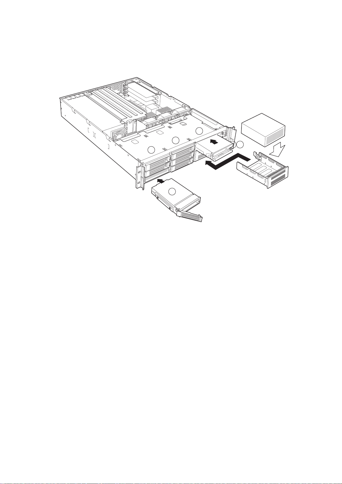
Replacing a CD-ROM Drive/FDD Module
CAUTION
A CD-ROM drive/FDD module is NOT hot swappable. Before replacing it, you must first
take the server out of service, turn off all peripheral devices connected to the sy stem, t urn
off the system by pressing the power button, and unplug the AC power cord from the
system or wall outlet.
1. Remove the bezel from the front of the chassis.
2. Rotate the handle bar (A) up about -inch (6-mm) to unlatch the module from the bay.
3. Grasp the handle bar at both ends and firmly pull out to disengage the connector.
(When you first pull, resistance will be high until the connector disengages.)
4. Slide the module out of the flex bay.
5. On the replacement module, rotate the handle bar down.
6. Insert the replacement module into the flex bay and slide it bac k until you feel the connectors
touch.
7. With your thumbs positioned above the handle bar indentations (B), push the module in
until it locks in place.
8. Reinstall the bezel.
34
B
A
B
Figure 20. Installing a CD-ROM Drive/FDD Module
Working Inside Your Server
Page 35

Replacing a PCI Add-in Card
1. Before removing the cover to work inside the system, observe the safety guidelines.
2. Remove the chassis cover.
3. Remove the riser card that contains the add-in card you wish to replace.
If you are replacing a low -profile add-in card, insert y our finger in the plastic loop (Figure
21, A) and lift the riser card assembly out of the chassis.
• If you are replacing a full-height add-in card, grasp the riser card at both ends of the
EMI shield and lift the riser card assembly out of the chassis.
4. Open the retainer clip (B) on the riser card retention bracket.
5. Pull the PCI card (C) out of the riser card slot.
6. Install the new PCI add-in card on the riser card.
7. Insert the riser card connector in the server board slot while aligning the tabs on the
rear retention bracket with the holes in the chassis.
CAUTION
Press the riser card straight down into the slot. Tipping it in the slot while installing it may
damage the riser card or board slot.
8. Firmly press the riser card straight down until it is seated in the server board slot.
9. Replace the chassis cover if you have no additional work to do inside the chassis.
C
B
A
MAXDATA PLATINUM Server Manual
Figure 21. Removing a Riser Card
35
Page 36

Replacing a Power Supply Module
The power supply system consists of the power supply bay and either one or two power
supply modules. The optional second module provides a redundant, 1+1 system.
CAUTION
If you do not have the second, redundant power supply module, you must take the server
out of service before replacing the single module.
1. Squeeze the module handle to depress the latch that is the right side of the handle.
2. Rotate the handle down (B) while pulling the module toward you (C). As you pull the
module out, support the module with your free hand.
3. Insert a new power supply module in the bay.
4. Grip the module handle, rotate it down, and push the module into the bay.
5. When the module is nearly all of the wa y in, the handle will rotate up. At this time, push
firmly on the front of the handle to lock the latch.
6. The po wer supply module is no w functional and the pow er supply f ault indicator should
not be lit.
A
B
C
Figure 22. Replacing a Power Supply Module
Replacing a Power Supply Cage
1. Unplug the power cord from the power source.
2. At the rear of the server, release the strain relief(s) and unplug the power cord(s) from
the power supply.
3. Remove the power supply modules.
4. Remove the chassis cover.
5. Remove the full-height PCI riser card.
6. Remove the fan assembly.
7. Disconnect and remove all data cabling necessary to gain access to the power cables.
8. Disconnect the main power connector from the server board.
9. Disconnect all other power cables from their devices.
36
Working Inside Your Server
Page 37

10. Remove the power cable bundle from the clip.
11. At the rear of the chassis, remove the two screws (A) that secure the power supply.
12. At the fan end of the power supply, remove the screw (C) that attaches the power
supply to the standoff in the chassis floor.
A
B
D
Figure 23. Replacing a Power Supply Cage
E
C
13. Lift the fan end of the power supply above the chassis standoff and slide it toward the
front of the server (D). Lift the power supply out of the chassis (E).
14. Place the new power supply in the chassis and slide it to the rear as far as it will go.
15. Install the two screws at the rear of the chassis and the one scre w at the fan end of the
power supply.
16. Place the power cables in the bundle clip.
17. Plug the main power connector into the server board.
18. Connect all other power cables to their devices.
19. Install the fan assembly and connect the fan power cables to the server board.
20. Install the full-height PCI riser card.
21. Route and connect all data cables.
CAUTION
Carefully route cables in their original paths to minimize airflow bloc k age andcooling problems.
22. Install the chassis cover.
23. Connect the power cord(s) to the power cord receptacle(s) and plug the cord(s) back
into the power source.
MAXDATA PLATINUM Server Manual
37
Page 38

Replacing a Fan
1. Before removing the cover to work inside the system, observe the safety guidelines.
2. Remove the cover from the chassis.
3. Remove the full-height PCI riser card.
4. Unplug the fan cables from the server board.
5. At the end of the fan assembly closest to the chassis centerline, lift up on tab (B) and
slide the fan assembly tow ard the chassis centerline (C) until it releases from the c hassis.
C
A
B
Figure 24. Removing the Fan Assembly
6. At the base of the failed fan, press down on tab and rotate the bottom of the fan out
(B) and remove it from the assembly.
38
Regulatory and Certification Information
Page 39

A
B
Figure 25. Removing a Fan
7. Insert the top of a new fan into the fan assembly and rotate the bottom in until tab (B)
locks it in place.
8. Place the fan assembly on the c hassis floor and slide it to ward the c hassis side wall until
it has engaged the chassis tabs and tab (A) has locked it in place.
9. Plug the fan cables into the server board system fan connectors.
10. Install the full-height PCI riser card.
11. Replace the chassis cover.
MAXDATA PLATINUM Server Manual
39
Page 40

Replacing a Backplane Board
1. Before removing the cover to work inside the system, observe the safety guidelines.
2. Remove the cover from the chassis.
3. Remove all hard drives and peripherals from their bays.
4. Remove the full-height PCI riser card assembly.
5. Remove the fan assembly.
6. Unplug all cables connected to the backplane board.
7. Remove the f our mounting screws along the top of the board and lif t it out of the chassis.
8. Lo wer the replacement bac kplane board into the c hassis, inserting the lower corners (B)
and (C) into their slotted chassis tabs.
9. Install and tighten the four mounting screws.
CAUTION
Carefully route cables in their original paths to minimize airflow bloc kage and cooling problems.
10. Connect all cables to the board.
11. Install the fan assembly.
12. Install the full-height PCI riser card.
13. Install all hard drives and peripherals in their bays.
14. Install the chassis cover.
A
B
C
40
Figure 26. Replacing a Backplane Board
Regulatory and Certification Information
Page 41

Replacing a Front Panel Board
1. Before removing the cover to work inside the system, observe the safety guidelines.
2. Remove the cover from the chassis.
3. Unplug the USB and backplane cables from the front panel board (A).
A
B
C
Figure 27. Removing the Front Panel Board
4. Remove the thumbscrew (B) from the board.
5. Remove the front panel board from the chassis (C).
6. Install the new board in the chassis being careful to insert the LED light pipes into the
front panel holes.
7. Secure the board to the chassis with the thumbscrew.
8. Plug the USB and backplane cables back into the front panel board.
9. Replace the chassis cover.
Replacing a Server Board
1. Before removing the cover to work inside the system, observe the safety guidelines.
2. Disconnect all cables from the rear I/O of the chassis.
3. Remove the cover from the chassis.
4. Remove the PCI riser cards.
5. Remove the fan assembly.
6. Unplug all cables connected to the server board.
7. Remove any processors, terminators, and memory cards that you wish to use with
the new board.
8. Remove the three mounting screws that secure the server board to the chassis.
MAXDATA PLATINUM Server Manual
41
Page 42

Figure 28. Removing the Server Board
9. Slide the board toward the front of the chassis until the I/O connectors are clear of the
chassis I/O openings and lift it from the chassis.
10. Ensure that the edge of the insulator sheet is below the studs in the rear chassis wall
and that the sheet is laying flat on the chassis floor.
1 1. Place the new server board on the chassis standoffs, being careful to position the board
I/O connectors in the rear chassis I/O openings.
12. Adjust board position so that the two mounting holes near the board edges rest securely
on the two corresponding shouldered standoffs.
13. Attach the board to the chassis using the three thumbscrews.
14. Install the processor(s), terminator, and memory cards that you wish to use with the
new board.
CAUTION
Carefully route cables in their original paths to minimize airflow bloc kage and cooling problems.
15. Cable the new server board to the other system components.
16. Install the fan assembly.
17. Install the PCI riser cards.
18. Replace the chassis cover.
19. Connect any cables removed from the rear I/O of the chassis.
42
Regulatory and Certification Information
Page 43

A Regulatory and Certification Information
WARNING
You must adhere to the assembly instructions in this guide to ensure and maintain compliance
with existing product certifications and approvals. Use only the described, regulated components
specified in this guide. Use of other products / components will void the UL Listing and other
regulatory approvals of the product, and will most likely result in noncompliance with product
regulations in the region(s) in which the product is sold.
Product Regulatory Compliance
The MAXD ATA PLATINUM 2200R c hassis subassembly, when correctly integrated per this
guide, complies with the following saf ety and electromagnetic compatibility (EMC) regulations.
Product Safety Compliance
• EN 60 950 (European Union)
• IEC60 950 (International)
• CE – Low Voltage Directive (73/23/EEC) (European Union)
Product EMC Compliance
• FCC /ICES-003, Class A Emissions (USA/Canada) Verification
• CISPR 22, 3rd Edition, Class A Emissions (International)
• EN55022, Class A Emissions (CENELEC Europe)
• EN55024: 1998, Immunity (CENELEC Europe)
• EN61000-3-2, Harmonics (CENELEC Europe)
• EN61000-3-3, Voltage Flicker (CENELEC Europe)
• CE – EMC Directive 89/336/EEC (CENELEC Europe)
MAXDATA PLATINUM Server Manual
43
Page 44

Electromagnetic Compatibility Notices
FCC Verification Statement (USA)
This device complies with Part 15 of the FCC Rules. Operation is subject to the following
two conditions: (1) This device may not cause harmful interference, and (2) this de vice must
accept any interference receiv ed, including interf erence that may cause undesired operation.
This equipment has been tested and found to comply with the limits for a Class A digital
device, pursuant to Part 1 5 of the FCC Rules. These limits are designed to provide reasonable
protection against harmful interference in a residential installation. This equipment generates,
uses, and can radiate radio frequency energy and, if not installed and used in accordance
with the instructions, may cause harmful interference to radio communications. However,
there is no guarantee that interference will not occur in a particular installation. If this
equipment does cause harmful interference to radio or television reception, which can be
determined by turning the equipment off and on, the user is encouraged to try to correct
the interference by one or more of the following measures:
• Reorient or relocate the receiving antenna.
• Increase the separation between the equipment and the receiver.
• Connect the equipment into an outlet on a circuit diff erent from that to whic h the receiver
is connected.
• Consult the dealer or an experienced radio/TV technician for help.
Any changes or modifications not expressly approved by the grantee of this device could
void the user’ s authority to operate the equipment. The customer is responsible for ensuring
compliance of the modified product.
Only peripherals (computer input/output devices, terminals, printers, etc.) that comply with
FCC Class A or B limits may be attached to this computer product. Operation with noncompliant peripherals is likely to result in interference to radio and TV reception.
All cables used to connect to peripherals must be shielded and grounded. Operation with
cables, connected to peripherals that are not shielded and grounded may result in interf erence
to radio and TV reception.
Europe (CE Declaration of Confor mity)
This product has been tested in accordance too, and complies with the Lo w V oltage Directive
(73/23/EEC) and EMC Directive (89/336/EEC). The product has been marked with the CE
Mark to illustrate its compliance.
44
Regulatory and Certification Information
Page 45

B Safety Warnings
WARNING: English (US)
MAXDATA PLATINUM Server Manual
45
Page 46

WARNING: English (US)
The power supply in this product contains no user-serviceable parts. There may be more than one
supp ly in this product. Refer servicing only to qualified personnel .
Do not attempt to modify or us e t he su pp lied AC power co rd if it is not the exact type required. A
product with more than one power supply will have a separate AC power cord for ea ch supply.
Th e pow er bu tt o n on th e syst em does no t tur n off system AC powe r. To r e mo v e AC power from
the system, you must unplug each AC power cord fro m th e wall o ut let or pow er su pply. The pow er
cord(s) is conside red the disco nn ect device to the mains (AC) po wer. Th e socket outlet that the
system plugs into shall be installed near the equipment and shall be easily accessible.
SAFETY STEPS: Whenever you remove the chassis covers to access the inside of the syste m,
follow these steps:
1. Turn off all peripheral devices con ne cted to the sy s tem.
2. Tu rn off the system by pressing the power button.
3. Unplug all AC power cords from the system or from wall outlets.
4. Label and disconn ect all cabl es connecte d to I/O connectors or ports on the back of the system.
5. Provid e some electrosta tic discharge (ESD) protection by wearing an antistatic wrist strap
attached to chassis groun d o f the system-any unpainted metal surface-when handling
components.
6. Do not operate the system with the chassis covers removed.
For proper cooling and airflow, always reinstall the chassis covers before turni ng on the system.
Operating the system without the covers in place can damage system parts. To install the covers:
1. Check first to make sure you have not left loose tools or parts inside the system.
2. Check that ca bl es, add-in boards, and other compon en ts are pr op erl y installe d.
3. Attach the covers to the chassis with the screws removed earlier, and t i ghten them firmly.
4. Inser t an d l ock the padlock to the system to prevent unauthorize d acce ss in sid e the system.
5. Connect all external cables and the AC power cord(s) to the sy stem.
A microprocessor and heat sink may be hot i f the system has been running. Also, ther e ma y b e
sharp pins and edges on some board and chassis parts. Contact should be made with care.
Consider wearing protective gloves.
Danger of explosion if the bat tery is incorrec tly replaced. Rep lace only with the same or equivalent
ty pe re c ommen ded by th e equipment manufacturer. Dispose of used batteries according to
manufacturer's instructions.
The system is designed to operate in a typical office environment. Choose a site that is:
·
Cl ean and free of airbo rne parti cle s (other than normal room dust).
·
Wel l-ve nt i l at ed an d a wa y from so urce s of heat includ in g di rect sunlight.
·
Away from sources of vibration or physical shock.
·
Isolated from strong electromagnetic fie lds pr odu c ed by el e ct r i c al dev ic es .
·
In r egions that are susceptible to electrical storms, we re c omm en d you pl ug your syste m in to a
surge suppre sser and disconne ct tel eco mmuni cation lines to your modem during an electrical
storm.
·
Provided with a properly grounded wall out le t .
·
Pro vid ed with sufficient space to access the power supply cord(s), because they serve as the
product's main power discon ne ct.
46
Regulatory and Certification Information
Safety Warnings
 Loading...