


MAXDATA PLATINUM 7200 Server
Product Guide
1MAXDATA PLATINUM 7200 Server

2 Contents 3MAXDATA PLATINUM 7200 Server

Contents
1 Important Safety Information ........................................................................7
Important Safety Information................................................................................................... 7
Intended Application Uses....................................................................................................... 7
Safety Instructions and Information......................................................................................... 7
Checking the Power Cords ...................................................................................................... 7
Multiple Power Cords .............................................................................................................. 7
Earth Grounded Socket-Outlets............................................................................................... 8
Before You Remove the Access Cover ................................................................................... 8
Power Supply Modules............................................................................................................ 8
Fans ......................................................................................................................................... 8
Electrostatic Discharge (ESD) .................................................................................................. 8
Cooling and Airflow.................................................................................................................. 9
Lifting and Moving ................................................................................................................... 9
Equipment Rack Precautions................................................................................................... 9
2 Getting Started..............................................................................................11
Selecting a Site ...................................................................................................................... 11
Space and Power Requirements ........................................................................................... 11
General Site Criteria............................................................................................................... 12
Turning On the Server and Running the Power-On Self-Test (POST).................................... 12
Hot Keys for POST................................................................................................................. 13
Installing the Service Partition (Recommended).................................................................... 13
Installing the Operating System............................................................................................. 14
System Security..................................................................................................................... 14
Using Passwords .............................................................................................................. 15
3 System Management.................................................................................... 17
Baseboard Management Controller....................................................................................... 17
Field Replaceable Units and Sensor Data Records ........................................................... 17
System Event Log............................................................................................................. 17
Platform Event Management ............................................................................................ 18
Emergency Management Port .......................................................................................... 18
Intel® Server Management .................................................................................................... 18
Using the System Setup Utility.............................................................................................. 19
Creating SSU Diskettes..................................................................................................... 19
Running the SSU............................................................................................................... 19
Working with the GUI ....................................................................................................... 20
Customizing the SSU Interface ......................................................................................... 20
Exiting the SSU ................................................................................................................. 21
Setting Boot Device Priority................................................................................................... 21
Setting Passwords and Security Options............................................................................... 21
Setting the Admin Password ............................................................................................ 21
Setting the User Password ............................................................................................... 21
Setting Security Options ................................................................................................... 22
Viewing the System Event Log ............................................................................................. 22
Viewing FRU Information....................................................................................................... 22
Viewing Sensor Data Records ............................................................................................... 23
Saving and Restoring the System Configuration ................................................................... 23
Saving a Configuration ...................................................................................................... 24
Restoring a Configuration.................................................................................................. 24
Alerting for Platform Events................................................................................................... 24
Setting Up Paging Alerts ................................................................................................... 24

5MAXDATA PLATINUM 7200 Server
Setting Up LAN Alerts....................................................................................................... 25
Managing the Server Remotely ............................................................................................. 26
Setting Up Remote LAN Access....................................................................................... 26
Setting Up Remote Modem or Serial Access ................................................................... 27
4 Installing and Removing Components ........................................................ 29
Removing and Installing the Bezel......................................................................................... 29
Memory ................................................................................................................................ 29
Installing DIMMs............................................................................................................... 29
Removing DIMMs............................................................................................................. 30
Hot-Swap SCSI Drives ........................................................................................................... 31
Checking a Hot-Swap SCSI Drive Status Indicator............................................................ 31
Installing a Hot-Swap Drive in a Carrier............................................................................. 32
Removing a Hot-swap Drive from a Carrier ...................................................................... 33
Removing and Installing Hot-Swap Disk Drives ................................................................ 34
DC Power Supplies................................................................................................................ 35
Checking the Power Status LEDs.......................................................................................... 35
Removing a Power Supply Module................................................................................... 36
Installing a Power Supply Module..................................................................................... 36
PCI Add-In Boards.................................................................................................................. 37
Operating System Support for Hot-Plug Add-In Boards......................................................... 38
Checking the Status Indicators for a Hot-Plug Add-In Board............................................. 38
Installing a Hot-Plug PCI Add-In Board .............................................................................. 39
Removing a Hot-Plug PCI Add-In Board ............................................................................ 40
Cooling System Fans ............................................................................................................ 40
Checking a Fan Status Indicator........................................................................................ 41
Removing a Fan Module ................................................................................................... 42
Installing a Fan Module ..................................................................................................... 42
5 Solving Problems ..........................................................................................43
Resetting the System ............................................................................................................ 43
Initial System Startup............................................................................................................. 43
Running New Application Software....................................................................................... 43
Application Software Checklist ......................................................................................... 43
After the System Has Been Running Correctly................................................................. 44
Monitoring POST ................................................................................................................... 44
Verifying Proper Operation of Key System Lights............................................................. 44
Confirming Loading of an Operating System......................................................................... 44
Specific Problems and Corrective Actions............................................................................. 45
Power Light Does Not Light.............................................................................................. 45
No Beep Codes ................................................................................................................. 45
No Characters Appear on Screen...................................................................................... 45
Characters Are Distorted or Incorrect ............................................................................... 46
System Cooling Fans Do Not Rotate Properly .................................................................. 46
Diskette Drive Activity Light Does Not Light .................................................................... 46
Hard Drive Activity Light Does Not Light .......................................................................... 47
CD-ROM Drive Activity Light Does Not Light ................................................................... 47
Network Problems................................................................................................................. 47
The server hangs when the drivers are loaded. ................................................................ 47
Diagnostics pass, but the connection fails........................................................................ 47
The Link LED does not light. ............................................................................................. 47
The Activity LED doesn’t light........................................................................................... 47
The onboard network interface controller (NIC) stopped
working when an add-in adapter was installed. ................................................................ 48
The add-in adapter stopped working without apparent cause. ......................................... 48
4 Contents

PCI Installation Tips ............................................................................................................... 48
Problems with Application Software...................................................................................... 48
Bootable CD-ROM Is Not Detected....................................................................................... 48
A Server Description......................................................................................... 49
Feature Summary .................................................................................................................. 49
Chassis Access...................................................................................................................... 50
Main Chassis Components.................................................................................................... 51
Electronics Bay Components................................................................................................. 51
Front Control Panel ................................................................................................................ 52
Rear Panel.............................................................................................................................. 53
Power Supplies...................................................................................................................... 53
System Cooling...................................................................................................................... 53
Server Board Set Features..................................................................................................... 54
Baseboard Connector and Component Locations ................................................................. 55
Baseboard Jumpers............................................................................................................... 56
Boot Block Jumpers .............................................................................................................. 56
Main Jumpers........................................................................................................................ 56
Serial Port B Jumpers ............................................................................................................ 57
DIMM Memory...................................................................................................................... 57
Onboard Video ....................................................................................................................... 57
Network Interface Controllers................................................................................................ 58
NIC Connector and Status LEDs ....................................................................................... 58
Network Teaming Features............................................................................................... 59
Adapter Fault Tolerance .................................................................................................... 59
Preferred Primary Adapter ............................................................................................... 59
Adaptive Load Balancing ................................................................................................... 60
Cisco Fast EtherChannel ................................................................................................... 60
ACPI....................................................................................................................................... 60
Hyper-Threading Technology ................................................................................................. 60
B Regulatory Information................................................................................. 61
Product Regulation Compliance Information ......................................................................... 61
Product Safety................................................................................................................... 61
Electromagnetic Compatibility (EMC) - Emissions ............................................................ 61
Electromagnetic Compatibility - Immunity ........................................................................ 61
Power Line Harmonics / Voltage Flicker ........................................................................... 61
Regional EMC Compliance Information................................................................................. 62
5MAXDATA PLATINUM 7200 Server

Figures
1. MAXDATA PLATINUM 7200.......................................................................................... 11
2. Attaching the Bezel to the Chassis ................................................................................ 29
3. Installing Memory........................................................................................................... 30
4. Removing DIMMs .......................................................................................................... 31
5. Hot-Swap SCSI Drive Bay and Status Indicators............................................................ 31
6. Removing a Plastic Air Bafe from a Carrier .................................................................. 32
7. Installing a SCSI Hard Disk Drive in a Carrier.................................................................. 33
8. Removing a Drive Carrier ............................................................................................... 34
9. Installing a Drive Carrier ................................................................................................. 34
10. Power and Standby LEDs............................................................................................... 35
11. Removing a Power Supply Module ................................................................................ 36
12. PCI Add-In Board Locations............................................................................................ 37
13. Status Indicators for Hot-Plug PCI Add-In Boards .......................................................... 38
14 Installing a Hot-Plug PCI Add-In Board ........................................................................... 39
15. Removing a Hot-Plug PCI Add-In Board ......................................................................... 40
16 Fan Status Indicator........................................................................................................ 41
17. Removing and Installing a Fan Module .......................................................................... 42
18. MAXDATA PLATINUM 7200 Server Hot-Swap Access ................................................. 50
19. Chassis with Bezel and Access Covers Removed ......................................................... 51
20. Electronics Bay Internal Components ............................................................................ 51
21. MAXDATA PLATINUM 7200 Front Control Panel ......................................................... 52
23. MAXDATA PLATINUM 7200 Server Rear Panel View ................................................... 53
23. Baseboard Connector and Component Locations.......................................................... 55
24. Baseboard Jumpers ....................................................................................................... 56
Tables
1. Safety Symbols ................................................................................................................ 7
2. MAXDATA PLATINUM 7200 Server Physical Specications ......................................... 11
3. Hot Keys......................................................................................................................... 13
4. Software Security Features............................................................................................ 14
4. Software Security Features (Continued) ........................................................................ 15
5. LED States for Hot-Swap SCSI Drive Status.................................................................. 32
6. LED Power Supply Status Indicators ............................................................................. 35
7. LED Hot-Plug PCI Status Indicators .............................................................................. 38
8. Feature Summary........................................................................................................... 49
9. Front Control Panel Features.......................................................................................... 52
10. Server Board Set Features ............................................................................................. 54
11. Boot Block Jumper Descriptions.................................................................................... 56
12. Main Jumper Descriptions ............................................................................................. 57
13. Serial Port B Jumper Descriptions ................................................................................. 57
14. Product Regulatory Compliance Markings ..................................................................... 61
15. Regional EMC Compliance Information ......................................................................... 62
6 Contents 7MAXDATA PLATINUM 7200 Server
1 Important Safety Information
Important Safety Information
Only a technically qualied person shall access, integrate, congure, and service this product.
Intended Application Uses
This product was evaluated as Information Technology Equipment (ITE), which may be
installed in ofces, schools, computer rooms, and similar commercial type locations. The
suitability of this product for other Product Categories and Environments (such as medical,
industrial, alarm systems, and test equipment), other than an ITE application, may require
further evaluation.
Safety Instructions and Information
To avoid personal injury or property damage, before you begin installing the product, read,
observe, and adhere to all of the following safety instructions and information. The following
safety symbols may be used throughout this product guide, and may be marked on the
product and or its packaging.
Table 1. Safety Symbols
Indicates the presence of a hazard that may cause minor personal injury or
CAUTION
WARNING
property damage if the CAUTION is ignored.
Indicates the presence of a hazard that may result in serious injury or death if the
WARNING is ignored.
Checking the Power Cords
WARNING
To avoid electrical shock, do not attempt to modify or use the supplied AC power cord(s), if
they are not the exact type required. If a power cord(s) supplied is not compatible with the
AC wall outlet in your region, get one that meets the following criteria:
• The power cord must be properly rated for the AC voltage in your region.
• The power cord plug cap must have an electrical current rating that is at least 125% of
the electrical current rating of the product.
• The power cord plug cap that plugs into the wall socket-outlet must have a grounding type male plug designed for use in your region.
• The power cord must have safety certifications for your region, and shall be marked
with the certification markings.
• The power cord plug cap that plugs into the AC receptacle on the power supply must
be an IEC 320, sheet C13, type female connector.
• In Europe, the power cord must be less than 4.5 meters (14.76 feet) long, and it must
be flexible <HAR> (harmonized) or VDE certified cordage to comply with the chassis’
safety certifications.
The power supply cord(s) is the main disconnect device to AC power. The socket outlet(s)
shall be near the equipment and shall be readily accessible for disconnection.
Multiple Power Cords
WARNING
To avoid electrical shock, disconnect all AC power cords before accessing inside the
system.

9MAXDATA PLATINUM 7200 Server
Earth Grounded Socket-Outlets
WARNING
To avoid electrical shock, the system power cord(s) must be plugged into socket-outlet(s)
that is provided with a suitable earth ground. The system will be provided with the following
marking:
Connect only to properly earthed socket outlet.
Before You Remove the Access Cover
WARNING
To avoid personal injury or property damage, the following safety instructions apply whenever
accessing inside the product:
• Turn off all peripheral devices connected to this product.
• Turn off the system by pressing the power button on the front of the product.
• Disconnect the AC power by unplugging all AC power cords from the system or wall
outlet.
• Disconnect all cables and telecommunication lines that are connected to the system.
• Retain all screws or other fasteners when removing access cover(s). Upon completion
of accessing inside the product, refasten access cover with original screws or fasten ers.
• Do not access inside power supply. There are no serviceable parts in the power supply.
Return to manufacturer for servicing.
Power Supply Modules
CAUTION
Power supply modules have double-pole/neutral fusing.
Fans
WARNING
To avoid injury do not contact moving fan blades.
Electrostatic Discharge (ESD)
CAUTION
Perform the procedures in this chapter only at an electrostatic discharge (ESD) workstation,
because the server components can be extremely sensitive to ESD. If no such station is available,
you can reduce the risk of electrostatic discharge ESD damage by doing the following:
• Wear an antistatic wrist strap and attach it to a metal part of the server.
• Touch the metal on the server chassis before touching the server components.
• Keep part of your body in contact with the metal server chassis to dissipate the static
charge while handling the components. Avoid moving around unnecessarily.
• Hold the server components (especially boards) only by the edges.
• Place the server components on a grounded, static-free surface. Use a conductive foam
pad if available but not the component wrapper.
• Do not slide the components over any surface.
8 Important Safety Information

Cooling and Airflow
CAUTION
For proper cooling and airow, always install all access covers before turning on the system.
Operating the system for longer than ve minutes without the covers in place can cause
overheating and damage to system components.
Lifting and Moving
CAUTION
Do not attempt to lift or move the server by the handles on the power supplies.
Equipment Rack Precautions
Follow the rack manufacturer’s safety and installation instructions for proper rack installation.
The following additional rack safety installation measures shall be considered:
CAUTION
The equipment rack must be anchored to an unmovable suitable support to prevent the rack
from falling over when one or more systems are fully extended out of the rack assembly.
You must also consider the weight of any other devices installed in the rack assembly. The
equipment rack must be installed according to the manufacturer’s instructions.
CAUTION
You are responsible for installing an AC power disconnect for the entire rack unit. This main
disconnect must be readily accessible, and it must be labeled as controlling power to the
entire unit, not just to the system(s).
CAUTION
To avoid the potential for an electrical shock hazard, the rack assembly itself must be suitably
earth grounded, according to your local regional electrical codes. This typically will require
the rack to have its own separate earth ground. We recommend you consult your local
approved electrician.
CAUTION
The system is designed to operate on a 20A AC voltage source that is provided with 20A
over current protection. If the AC source for the rack exceeds 20A over current protection,
each system must be provided with 20A or less over current supplemental protection. The
supplementary over current protection must have the appropriate regional safety certifications
for the over current application.
CAUTION
The operating temperature of the system, when installed in the rack, must not go below
10° C (50° F) or rise above 35° C (95° F). Extreme fluctuations in temperature may cause a
variety of problems in system, and safety limits may be broken.
CAUTION
The equipment rack must provide sufficient airflow to the front of the system to maintain
proper cooling. The rack selected and the ventilation provided must be suitable to the
environment in which the system will be used.
9MAXDATA PLATINUM 7200 Server

10 Important Safety Information 11MAXDATA PLATINUM 7200 Server
2 Getting Started
Selecting a Site
This section describes the space and power requirements and general site criteria for
installing the server.
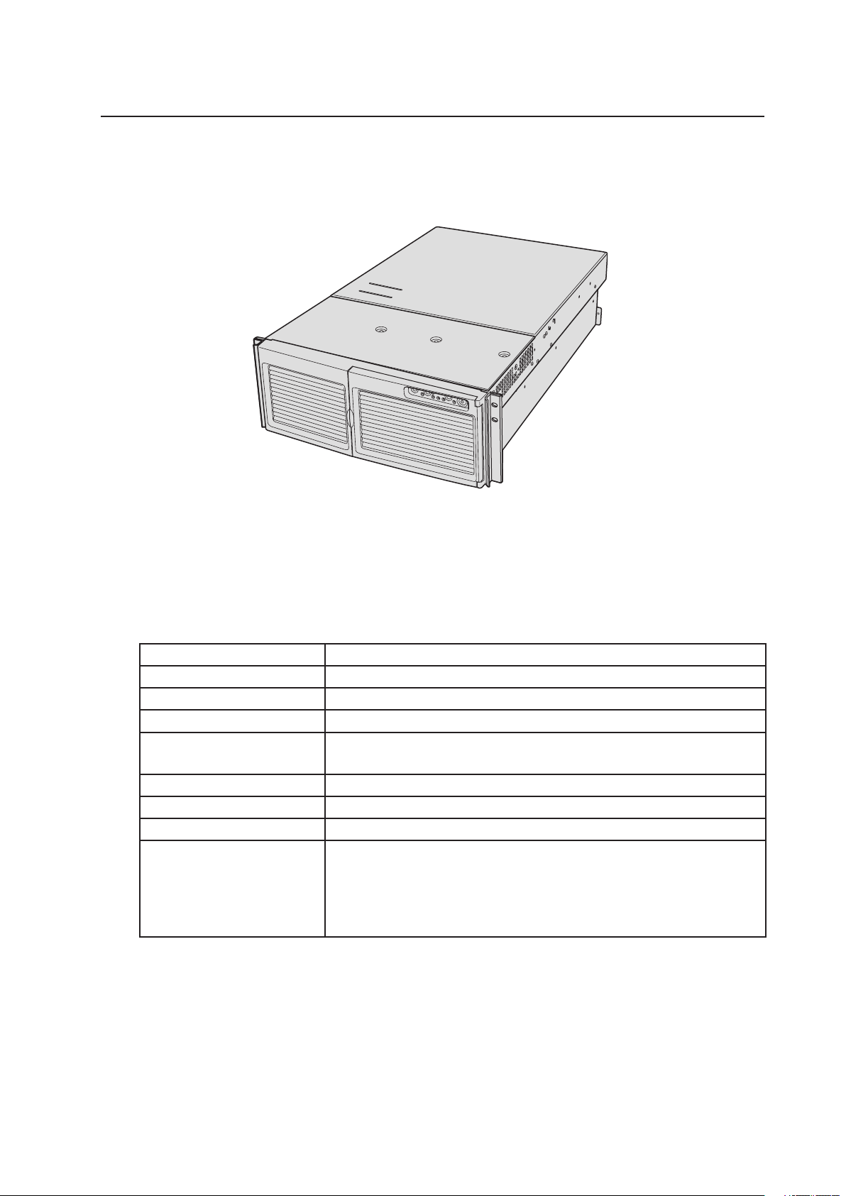
Figure 1. MAXDATA PLATINUM 7200 Server
Space and Power Requirements
Table 2. MAXDATA PLATINUM 7200 Server Physical Specications
Specication
Height
Width
Depth
Weight
Required front clearance
Required rear clearance
Required side clearance
Power requirements
Voltage (110)
Voltage (220)
Frequency
Rack Mode Only
7 inches (178 mm) (4u)
17.5 inches (445 mm)
28.0 inches (711 mm)
57 pounds (25.9 kg), minimum configuration
88 pounds (39.9 kg), maximum configuration
3 inches (76 mm), inlet airflow <35° C (95° F)
4.5 inches (114 mm), no airflow restriction
1 inch (25 mm)
90 Vrms min, 132 Vrms max, 8 Arms*
180 Vrms min, 264 Vrms max, 4 Arms*
47 Hz min, 63 Hz max
* Amperage is total system power, with two or three power supply modules installed, with one or two AC cords.

13MAXDATA PLATINUM 7200 Server
General Site Criteria
The server operates reliably within normal office environmental limits. Select a site that meets
these criteria:
• Near a properly grounded, three-pronged power outlet.
– In the United States and Canada: a NEMA 6-15R outlet for 100-120 V and for 200-240 V.
– In other geographic areas: a properly grounded outlet in accordance with the local
electrical authorities and electrical code of the region.
• Clean and relatively free of excess dust.
• Well ventilated and away from sources of heat, with the ventilating openings on the
server kept free of obstructions.
• Maximum ambient air temperature should not exceed 35° C (95° F).
• Away from sources of vibration or physical shock.
• Isolated from strong electromagnetic fields and noise caused by electrical devices such
as elevators, copy machines, air conditioners, large fans, large electric motors, radio and
TV transmitters, and high-frequency security devices.
• Access space provided so the server power cords can be unplugged from the power
supply or the wall outlet; this is the only way to remove AC power from the server.
• Clearance provided for cooling and airflow.
Turning On the Server
and Running the Power-On Self-Test (POST)
Each time you start the server, the Power-On Self-Test (POST) runs automatically. POST is
stored in flash memory. To start the server, do the following:
1. Make sure all external devices, such as a monitor, keyboard, and mouse, are connected.
2. If a drive protection card or diskette is present in the diskette drive, remove it.
3. Plug the video monitor power cord into the power source or wall outlet. Turn on the video
monitor.
4. Plug the AC power cords into the power connectors on the back of the chassis and into
the power source or wall outlet.
5. If the server does not turn on when you plug it into the AC outlet, press the on/off power
button on the front panel.
6. Verify that the main power LED on the front panel is lit .
7. Insert the MAXDATA PLATINUM 7200 Server Platform System Resource CD into the CD-
ROM drive.
After a few seconds, POST begins and a splash screen is displayed (if the splash screen is
disabled in BIOS Setup, a diagnostics screen is displayed). POST discovers, configures, and
tests the processors, memory, keyboard, and most installed peripheral devices. The length of
time needed to complete POST depends on the amount of memory installed and the number
of option boards installed.
8. Shortly after the splash screen is displayed, POST displays the message “Press <F2>
to enter Setup…” at the bottom of the screen. If you enter BIOS Setup, the Service Partition,
or the Adaptec SCSISelect Utility, when you exit those features, the server might
reboot.
9. After POST completes, the system beeps once and then searches all boot devices in the
order dened by the boot priority settings in the BIOS. The system nds, loads, and runs
the limited operating system on the System Resource CD.
12 Getting Started

NOTE
If there is no device with a bootable operating system, the boot process continues, the
system beeps once, and the following message is displayed:
Operating System not found
If you have a device with a bootable operating system but see this message anyway, reboot
and use BIOS Setup to make sure your boot device settings are correct.
Hot Keys for POST
Table 3 lists the hot keys you can use during POST to access setup utilities and alter the
normal POST execution.
Table 3. Hot Keys
To Do This: Press These Keys:
Abort memory test during POST.
Resume after a POST error is displayed. (The
system pauses after displaying an error.)
Enter BIOS Setup during POST.
Boot to the service partition.
Boot from a network using Preboot Execution
Environment (PXE).
Remove the splash screen to view the diagnostic messages during POST and display a
menu for selecting the boot device.
Enter the Adaptec SCSISelect Utility during POST.
* Press any of these keys when the prompt “Press <F2> to enter Setup…” is displayed.
<Space>
Press while BIOS is updating memory size on
screen.
<F1>
<F2>*
<F4>*
<F12>*
<ESC>*
Note: Using BIOS Setup, you can enable the BootTime Diagnostic Screen, in which case POST does
not display the splash screen.
Note: If you use the displayed menu to change the
boot device, the change affects the current boot
only.
<Ctrl+A>*
Installing the Service Partition (Recommended)
When you are setting up your server system, you can install a service partition on your hard
drive. The service partition, in conjunction with Intel® Server Management (ISM) software,
provides emergency remote management and remote server setup. The service partition
lets you remotely access a local partition on the server and identify and diagnose server
health issues by using either a modem or network connection. The service partition uses
approximately 30 to 40 MB of hard disk space.
NOTE
MAXDATA strongly recommends that you install the service partition before installing an operating
system. If you skip this step now, and later decide to install a service partition, any operating
system or other data on the drive will be lost. To create and format the service partition:
1. Boot the server to the System Resource CD.
2. From the menu, select Utilities and press the <Enter> key.
3. Select Run Service Partition Administrator and press the <Enter> key.
4. From the list of available items, select Create Service Partition-first time.
5. Follow the instructions that appear on the screen. These instructions prompt you to
reboot the server. It will reboot from the CD-ROM.
13MAXDATA PLATINUM 7200 Server

15MAXDATA PLATINUM 7200 Server
6. After the system reboot, select the Utilities menu and press the <Enter> key.
7. Select Run Service Partition Administrator and press the <Enter> key.
8. Select Format Service Partition and Install Software.
9. Remove the System Resource CD from the CD-ROM drive and exit from the menu
screen.
You can now install the operating system.
Installing the Operating System
The System Resource CD contains a limited operating system with enough functionality to
boot the server and to copy and use the utilities and other files from the CD. This limited
operating system is not intended to be used to run applications. To run your server and
applications, you must install the operating system of your choice on the server. Follow the
installation instructions that came with the operating system.
System Security
Table 4 summarizes the security features provided by the BIOS to prevent unauthorized or
accidental access to the system. You can enable these features using the Security section
of BIOS Setup. Most of the features can also be enabled using the System Setup Utility
(SSU). Additional information on passwords is provided following the table.
Table 4. Software Security Features
Feature Description
Secure Mode
Secure Mode Boot
To enable secure mode: Set a user password.
To enter secure mode, do one of the following:
• Press the hot-key combination for secure mode. You can specify a hotkey combination, which must consist of Ctrl+Alt plus one alphanumeric
character.
• Let the inactivity timer time out. If you don’t touch the keyboard during the
time-out period, the system enters secure mode automatically. You can set
the time-out period from two minutes to 120 minutes.
• Power on or reset the system. The system automatically enters secure
mode on power up.
When the system is in secure mode:
• Onboard video is blanked, if enabled.
• Diskette drive is write protected, if enabled.
• Power, Sleep, and Reset buttons on the front panel are disabled.
• Mouse and keyboard input are ignored, except for entering a password.
• The keyboard LEDs ash.
To enable, do both of the following:
• Set a user password.
• Enable Secure Mode Boot.
To activate: Power on or reset the server.
When enabled:
• If booting from drive A: the user must enter a password. After the user
enters the password, the system continues with the boot process. The
system doesn’t enter secure mode until activated by the hot-key or timer.
• If the system is not booting from drive A: the system boots normally. No
password is required, and the system enters secure mode automatically.
The system boots according to the boot device priority set in BIOS Setup.
continued
14 Getting Started

Table 4. Software Security Features (Continued)
Feature Description
Password on Boot
Fixed Disk Boot Sector Write Protect
Power Switch
Inhibit
To enable, do all of the following:
• Set a user password.
• Enable Password on Boot.
• Disable Secure Mode Boot.
To activate: Power on or reset the server.
When enabled: The user must enter a password to boot the system. The system
boots according to the boot device priority set in BIOS Setup.
To enable, do the following:
• Set Fixed Disk Boot Sector to Write Protect in the Security section of BIOS
Setup.
To activate: Power on or reset the server.
When enabled: Write protects the master boot record of the IDE hard disk drive
when the system boots from drive A:. Prevents viruses from corrupting the boot
sector under DOS. Works only with IDE drives.
To enable: Enable Power Switch Inhibit.
To activate: Power on or reset the server.
When enabled: The power switch can’t be used to power off the system.
Using Passwords
Passwords are up to seven characters long; may use only the alphanumeric characters a-z,
A-Z, and 0-9; and are not case sensitive.
You set administrator and user passwords in BIOS Setup and in the SSU. When you have
either password set, you must enter that password to do any of the following:
• Enter BIOS Setup and the SSU.
• Boot the server from drive A: when Secure Boot Mode is enabled.
• Boot the server when Password on Boot is enabled.
• Exit secure mode.
When you have both a user and an administrator password set, you may enter either
password. However, if you enter the user password for BIOS Setup or the SSU, you will be
able to modify only the time, date, language, user password, secure mode timer, and secure
mode hot-key. To modify any other features, you must enter the administrator password.
You can clear a password by setting it to a blank string. If you forget your passwords, you
can use the Password Clear jumper to clear the passwords on the next boot.
15MAXDATA PLATINUM 7200 Server

16 Getting Started 17MAXDATA PLATINUM 7200 Server

3 System Management
Baseboard Management Controller
The MAXDATA PLATINUM 7200 server incorporates a baseboard management controller
(BMC), which is a dedicated microcontroller for system management activities. The BMC
performs the following functions:
• Monitors system components and sensors, including processors, memory, fans,
power supplies, temperature sensors, and chassis intrusion sensors.
• Manages nonvolatile storage for the system event log (SEL), sensor data records (SDRs),
and baseboard field-replaceable unit (FRU) inventory.
• Interfaces with the emergency management port (EMP) and LAN1 port to send alerts
and interact with remote management systems.
• Provides the main front panel control functions (power on/off, reset, and so on).
Field Replaceable Units and Sensor Data Records
Field replaceable units (FRUs) are major modules in the chassis that contain active electronic
circuitry. FRUs can store information – such as board serial number, part number, name, and
asset tag – that can be read using the System Setup Utility. The BMC stores FRU information
for the baseboard in a nonvolatile storage component on the board.
The BMC uses Sensor Data Records (SDRs) to identify the sensors in the system for
monitoring. SDRs provide a list of the sensors, their characteristics, location, type, and
type-specific information, such as default threshold values, factors for converting a sensor
reading into the appropriate units (mV, rpm, degrees Celsius), and information on the types
of events that a sensor can generate. The BMC stores SDR information in a nonvolatile
storage component on the baseboard.
System Event Log
The BMC manages a system event log (SEL), where it records significant or critical system
events. Such events include temperatures and voltages out of range, fan failures, and other
sensor-related events. The BIOS, software, add-in cards, and other devices can also log
events by sending messages to the BMC. The SEL is stored in nonvolatile storage.
You can view the current contents of the SEL by using the System Setup Utility .

19MAXDATA PLATINUM 7200 Server
Platform Event Management
Events can trigger alerts and other actions by the BMC. The server is configured with the
following set of standard events:
• Temperature sensor out of range
• Voltage sensor out of range
• Fan failure
• Chassis intrusion
• Power supply fault
• BIOS uncorrectable ECC error
• BIOS POST error
• Processor fault resilient booting (FRB) failure
• Fatal nonmaskable interrupt (NMI) from a source other than the front panel switch
• Watchdog timer reset, power down, or power cycle
• System restart (reboot)
Alerts can take either of these forms:
• Platform event pages − the BMC dials a paging service and sends a predefined paging
string. To use platform event paging (PEP), you must attach an external modem to the
emergency management port (COM2).
• BMC LAN alerts − the BMC sends an alert to a predefined destination on the LAN.
You can configure PEP and BMC LAN alerts by using the System Setup Utility .
Emergency Management Port
The emergency management port (EMP) refers to the use of the COM2 port, with either
an external modem or direct serial connection, for remote management. The BMC controls
the port and interfaces with remote access software, such as the Direct Platform Control
application in Intel® Server Management. You can congure the EMP by using the System
Setup Utility .
Intel® Server Management
Intel® Server Management (ISM) is a system management package that is included on the
System Resource CD or on a separate ISM CD. ISM applications interact with the integrated
hardware system management features of the server to allow you to monitor and manage
a server from a remote workstation:
• Remote connection from a Windows®-based client workstation over a LAN, or over
a modem or direct serial connection to the emergency management port on the server.
• Real-time monitoring and alerting for server hardware sensors.
• Emergency management when the server is off (but still connected to AC power) lets
you verify the state of the server, diagnose hardware problems, and power on/off or
reset the server.
• Run the System Setup Utility to change the server configuration.
• Run diagnostics tools similar to those used during factory testing.
ISM depends on a service partition on the server that you are managing. The service partition
is a special disk partition on the system drive that contains a ROM-DOS operating system and
DOS-based utilities, including the System Setup Utility, FRU/SDR Load Utility, and Remote
Diagnostics. The server can be booted to the service partition, either locally or remotely, to
provide access to the utilities.
18 System Management

Using the System Setup Utility
The System Setup Utility (SSU) is located on the System Resource CD-ROM shipped with
the server.
Run the System Setup Utility to:
• Set boot device priority
• Set passwords and security options
• View system events
• View FRU information
• View sensor data records
• Update system firmware and BIOS
• Save and restore the system configuration
• Set up the server to send alerts for platform events
• Set up the server for remote management
Using either the System Setup Utility or BIOS Setup, you can specify the boot device
sequence and set up system passwords and security options. Both utilities access the
same stored configuration data for these items, and the result of making a change to these
settings using either utility is identical.
The SSU consists of a collection of task-oriented modules plugged into a common framework called the Application Framework (AF). The Application Framework provides a launching
point for individual tasks and a location for setting customization information.
Creating SSU Diskettes
You can run the SSU directly from the Utilities menu of the System Resource CD-ROM,
from a set of DOS diskettes, or from the service partition of the hard disk.
If you choose to run the SSU from a set of DOS diskettes, you must create the SSU diskettes
from the Resource CD-ROM as follows:
1. Boot to the System Resource CD-ROM.
2. Choose Create Diskettes > Create Diskettes by Device/Function > System Setup
Utility.
3. Follow the instructions displayed.
Alternatively, if you have a workstation with the Microsoft® Windows® operating system,
you can insert the CD into that system and create the diskettes on that system.
Running the SSU
When the SSU starts in the default local execution mode, the SSU accepts input from the
keyboard or mouse. The SSU presents a VGA-based GUI on the primary monitor.
If you run the SSU from read-only media, such as the CD-ROM, you cannot save user
preference settings (such as screen colors).
The SSU supports ROM-DOS version 6.22. The SSU will not operate from a “DOS box”
running under an operating system such as Windows®.
19MAXDATA PLATINUM 7200 Server

21MAXDATA PLATINUM 7200 Server
To start the SSU:
1. Start the SSU using one of the following methods:
− From diskettes: Insert the first SSU diskette in drive A and boot the server from the
diskette. You are prompted to insert the second diskette. After loading completes the
SSU starts automatically.
− From the System Resource or ISM CD-ROM: Boot the server to the System Resource
CD and start the SSU from the Utilities menu.
− From the Service Partition: Boot the server to the Service Partition and execute the
following DOS commands:
C:\> cd ssu
C:\SSU> ssu.bat
2. The mouse driver loads if it is available; press <Enter> to continue.
3. When the SSU title appears on the screen, press <Enter> to continue.
Working with the GUI
You can access features of the GUI using the mouse or keyboard:
• Mouse − Click once to choose menu items and buttons or to select items in a list, such
as the Available Tasks list. To run a list item, such as one of from the Available Tasks
list, select the item and click OK or double-click the item.
• Keyboard − Use the tab and arrow keys to highlight buttons and press the spacebar
or <Enter> to execute. You can also execute a menu or button by using the <Alt> key
in combination with the underlined letter in the name of the menu or button.
You can have more than one task open at the same time, although some tasks might require
complete control to avoid possible conflicts. The tasks achieve complete control by keeping
the task as the center of operation until you close the task window.
The SSU has a build-in help system, which you access by clicking a Help button or choosing
the Help menu.
Customizing the SSU Interface
The SSU lets you customize your interface using the Preferences section of the main window.
The AF sets these preferences and saves them in the AF.INI file so that they take effect the
next time you start the SSU. There are four user customizable settings:
• Color − lets you change the default colors associated with different items on the
screen using predefined color combinations. The color changes take effect imme diately.
• Mode − lets you set the desired expertise level: novice, intermediate, or expert.
The expertise level determines which tasks are visible in the Available Tasks section and
which actions each task performs. For a new mode setting to take effect, you must exit the
SSU and restart it.
• Language − lets you change the text in the SSU to the appropriate language. For a
new language setting to take effect, you must exit the SSU and restart it.
• Other − lets you show or hide the status bar at the bottom of the SSU main window.
The change takes effect immediately.
NOTE
If you run the SSU from read-only media (CD-ROM, for example), these preferences are lost
when you exit the SSU.
20 System Management

Exiting the SSU
Exiting the SSU closes all SSU windows.
Setting Boot Device Priority
To change the boot priority of a device:
1. From the SSU Main window, choose Boot Devices.
2. In the Multiboot Options Add-in window, select a device.
3. Click the Move Up button to move it up in the list. Click the Move Down button to move
it down.
Setting Passwords and Security Options
You can set a user password and an admin password. On some systems, you must set an
admin password before you can set a user password. On other systems, the passwords are
independent. You can set the same passwords and security options by using BIOS Setup (37).
Setting the Admin Password
The Admin Password button lets you set or change the admin password used by both the
SSU and the system BIOS. This option is not available if both an admin and a user password
are set and you entered only the user password when you started the SSU. All changes to
the admin password take effect immediately.
To change or clear the administrator password:
1. From the SSU Main window, choose Security.
2. Click the Admin Password button.
3. If you are changing passwords, enter the old password.
4. Enter the new password (or leave blank to clear).
5. Confirm the password by entering it again (or leave blank to clear).
6. Click OK to save the password and return to the Security window.
Setting the User Password
The User Password button lets you set or change the user password used by both the SSU
and the system BIOS. All changes to the user password take effect immediately.
To change or clear the user password:
1. From the SSU Main window, choose Security.
2. Click the User Password button.
3. If you are changing passwords, enter the old password in the rst box.
4. Enter the new password (or leave blank to clear).
5. Conrm the password by entering it again (or leave blank to clear).
6. Click OK to save the password and return to the Security window.
21MAXDATA PLATINUM 7200 Server

23MAXDATA PLATINUM 7200 Server
Setting Security Options
To set the security options:
1. In the Security window, click the Options button.
2. For each option, select the desired setting from the list. The options are:
• Security Hot Key: The key combination that can be used to put the server into secure
mode.
• Secure Mode Timer: If no keyboard or mouse activity occurs during the chosen time
interval, the server enters secure mode.
• Secure Mode Boot: Enable forces the server to boot directly into secure mode.
• Video Blanking: Enable turns off the video when the server is in secure mode.
• Floppy Write: Enable prevents writing to the diskette drive while the server is in secure
mode.
• Power Switch Inhibit: Enable prevents the power and reset buttons from function-
ing when the server is in secure mode. Disable allows the power and reset buttons
to function normally when the server is in secure mode.
3. Click Save to save the settings and return to the Security window.
Viewing the System Event Log
To view the System Event Log (SEL):
1. From the SSU Main window, choose SEL Manager.
When you start the SEL Manager, it automatically loads the current list of events from nonvolatile memory.
2. Use the <F4> and <F5> keys to scroll the window contents to the left and right to view
all of the columns.
3. Use the File and SEL menu items to work with the SEL information:
• Open: Views data from a previously saved SEL file.
• Save As: Saves the currently loaded SEL data to a file.
• Properties: Displays information about the SEL.
• Clear SEL: Clears the SEL data from the nonvolatile storage area.
• Reload: Refreshes the display by reading the current SEL entries from the server.
• Sort By: Sorts the displayed events by event number, time stamp, sensor type and
number, event description, or event generator ID.
Viewing FRU Information
To view the Field Replaceable Unit (FRU) information:
1. From the SSU Main window, choose FRU Manager.
When you start the FRU Manager, it automatically loads the current list of events from nonvolatile memory.
The FRU Manager window has a navigation pane on the left that displays, in a tree format,
the inventory of components in the server. The tree has three categories: Chassis, Board, and
Product. Clicking on a category expands or collapses a list of components for that category.
Clicking on an individual component displays the FRU information for that component in
the presentation pane in the upper right. The description pane in the lower right displays a
description of the currently selected FRU area.
22 System Management

2. Use the <F4> and <F5> keys to scroll the window contents to the left and right to view
all of the columns.
3. Use the File and FRU menu items to work with the FRU information:
• Open: Views data from a previously saved FRU file.
• Save As: Saves the currently loaded FRU data to a file.
• Properties: Displays the number of FRU devices in the system and the number being
displayed. Only FRU devices with valid FRU areas are displayed.
• Reload: Refreshes the display by reading the current FRU entries from the server.
Viewing Sensor Data Records
To view the Sensor Data Records (SDR):
1. From the SSU Main window, choose SDR Manager.
When you start the SDR Manager, it automatically loads the SDR entries from non-volatile
memory.
The SDR Manager window has a navigation pane on the left that displays, in a tree format, the
sensor data records. The tree has categories for each type of record. Clicking on a category
expands or collapses a list of SDRs for that category. Clicking on an individual SDR displays
the information for that SDR in the presentation pane in the upper right. The description
pane in the lower right displays a description of the currently selected SDR type.
2. Use the <F4> and <F5> keys to scroll the window contents to the left and right to view
all of the columns.
3. Use the File and SDR menu items to work with the SDR information:
• Open: Views data from a previously saved SDR file.
• Save As: Saves the currently loaded SDR data to a file.
• Properties: Displays information about the SDR, including IPMI version, number of
SDR entries, time stamps for changes to the SDR information, and free space
remaining.
• Reload: Refreshes the display by reading the SDR data from the server.
Saving and Restoring the System Configuration
Using the SSU, you can save the following configuration information to a file:
• Platform type, BIOS revision, and firmware revision
• CMOS settings
• Extended system configuration data (ESCD)
• Settings for the emergency management port (EMP), platform event paging (PEP), and
BMC LAN alerts
Data is saved from all sources. There is no way to choose only certain pieces of configuration
data to save. You can also restore the information from a saved configuration file.
NOTE
BIOS passwords are stored in the le. Restoring a conguration can change passwords on
a server. EMP and LAN passwords are not stored in the le.
23MAXDATA PLATINUM 7200 Server

25MAXDATA PLATINUM 7200 Server
Saving a Configuration
To save the system configuration:
1. From the SSU Main window, choose Config Save/Restore. (Configuration Save/Restore
is available only in Expert mode.)
2. Click Save To File and specify a filename and location.
Restoring a Configuration
To restore the system configuration from a file:
1. From the SSU Main window, choose Config Save/Restore. (Configuration Save/Restore
is available only in Expert mode.)
2. Click Restore from File and specify a filename and location.
The CSR reads the platform type, BIOS revision, and firmware revision from the file and
compares that information with the same information retrieved from the server. If the two
do not match, an error message is displayed and the restore operation aborts. If they do
match, the CSR restores the configuration data to the server. It prompts you to reboot the
server for the new settings to take effect.
Alerting for Platform Events
You can set up the server to alert you when various events occur. Alerts can be delivered
either as telephone pages or over the LAN. Instructions for setting up both telephone paging
alerts and LAN alerts are given below.
Setting Up Paging Alerts
To set up the server to send alerts as telephone pages:
1. Install an external modem on the Emergency Management Port (COM2).
2. From the SSU Main window, choose Platform Event Manager (PEM).
3. In the PEM window, click Configure EMP.
4. In the corresponding boxes, enter the following command strings for the modem attached
to the EMP port:
• ESC Sequence: the escape sequence. This string is sent to the modem before sending
command strings. The maximum length for the string is five characters; longer strings
are truncated.
• Hangup String: hang up or drop the connection. The EMP automatically sends an
<ENTER> character following this string. The maximum length for the string is
eight characters; longer strings are truncated.
• Modem Dial Command: the command to dial a phone number. This string is sent to
the modem before sending the paging string.
• Modem Init String: the initialization string for the modem. This string is sent every
time the EMP initializes. The maximum length for the string is determined at runtime
from firmware. You will be notified if the string is truncated. Following a save, the
actual string saved is displayed in the edit box.
5. Click Save to save the changes.
6. Click Close to return to the PEM window.
7. In the PEM window, click Configure PEP.
8. Select the Enable PEP check box.
24 System Management

9. In the Blackout Period box, enter the minimum time, in minutes, between successive
pages. The valid range is [0 - 255] where 0 disables the blackout period. Setting a blackout
period can save you from being flooded with repeat pages. After you receive a PEP page,
no additional pages are sent by PEP for the duration of the blackout period.
10. In the Paging String box, enter the phone number to dial for the page and the message
you want sent with the page. The maximum length for the paging string is determined
at runtime from firmware. You will be notified if the string is truncated. Following a save,
the actual string saved is displayed in the edit box.
11. From the Options menu, choose Configure Event Actions.
12. In the Platform Event Paging Actions window, move the events that you want to generate an
alert to the Enabled column and move all other events to the disabled column using
the following buttons:
>>: Moves all events from the enabled list to the disabled list.
>: Moves the selected event from the enabled list to the disabled list.
<: Moves the selected event from the disabled list to enabled the list.
<<: Moves all events from the disabled list to the enabled list.
13. Click Save to save the changes.
14. Click Close to return to the PEP Configuration window.
15. To send a test page to verify that you have correctly configured PEP, from the Options
menu, choose Send Alert.
16. Click Save to save the configuration.
17. Click Close to return to the Platform Event Manager window.
Setting Up LAN Alerts
To set up the server to send alerts over the LAN:
1. Configure the remote system to receive alerts. For more information, see the documen-
tation for Intel® Server Management software.
2. From the SSU Main window, choose Platform Event Manager (PEM).
3. In the PEM window, click Configure LAN.
4. Select the Enable LAN Alerts check box.
5. (Optional) In the SNMP Community String box, enter a string for the community field in the
Header section of the SNMP trap sent for an alert. The string must be from 5 to 16
characters. The default string is public.
6. In the IP Setup box, choose either:
• DHCP: the IP address for the server is automatically assigned by the DHCP
(dynamic host control protocol) server on the network. The Host, Gateway, and Subnet
Mask boxes in the dialog are ignored.
• Static: assign the IP address for the server using the Host, Gateway, and Subnet Mask
boxes in the dialog.
7. If you chose Static IP Setup in the previous step, fill in the IP addressing boxes:
• Host IP Address: the IP address of this server.
• Gateway IP Address: the IP address of the router for this server.
• Subnet Mask: the IP address for the server’s subnet. The server uses this to decide
if the alert destination is on the same subnet.
25MAXDATA PLATINUM 7200 Server

27MAXDATA PLATINUM 7200 Server
8. In the Alert IP Address box, fill in the IP address of the system you want to receive alerts
from this server. If you want the alert to be broadcast to an entire subnet, enter the IP
address for the subnet.
9. From the Options menu, choose Configure Event Actions.
10. In the BMC LAN Alerting Actions window, move the events that you want to generate
an alert to the Enabled column and move all other events to the disabled column
using the following buttons:
>>: Moves all events from the enabled list to the disabled list.
>: Moves the selected event from the enabled list to the disabled list.
<: Moves the selected event from the disabled list to enabled the list.
<<: Moves all events from the disabled list to the enabled list.
11. Click Save to save the changes.
12. Click Close to return to the BMC LAN Configuration window.
13. To send a test alert to verify that you have correctly configured BMC LAN alerts, from
the Options menu, choose Send Alert.
14. Click Save to save the changes.
15. Click Close to return to the PEM window.
Managing the Server Remotely
You can set up the server so that you can connect to it from a remote client system to
perform management tasks. You can make the connection over a LAN or by using a modem
or direct serial cable to the Emergency Management Port (EMP). Instructions for setting up
the server for remote LAN and serial/modem access are given below.
Setting Up Remote LAN Access
To configure remote LAN access:
1. From the SSU Main window, choose Platform Event Manager (PEM).
2. In the PEM window, click Configure LAN.
3. If you want to require a password for remote access, enter the password in the Enter New
Password box and in the Verify New Password box. Passwords can be from 1 to
16 characters long, using any ASCII character in the range [32-126]. To clear the passwords,
leave both boxes blank. (You can also clear the password by choose the menu Options >
Clear LAN Password.)
4. From the LAN Access Mode list, select the remote access mode:
• Full Access: a remote system can initiate a LAN connection regardless of the state
or health of the server.
• Restricted: a remote system can initiate a LAN connection, but cannot perform control
operations such as power down, reset, or front panel NMI.
• Disabled: remote systems are not allowed to initiate LAN connections.
5. In the IP Setup box, choose either:
• DHCP: the IP address for the server is automatically assigned by the DHCP
(dynamic host control protocol) server on the network. The Host, Gateway, and Subnet
Mask boxes in the dialog are ignored.
• Static: assign the IP address for the server using the Host, Gateway, and Subnet Mask
boxes in the dialog.
26 System Management

6. If you chose Static IP Setup in the previous step, fill in the IP addressing boxes:
• Host IP Address: the IP address of this server.
• Gateway IP Address: the IP address of the router for this server.
• Subnet Mask: the IP address for the server’s subnet. The server uses this to decide
if the alert destination is on the same subnet.
7. Click Save to save the changes.
8. Click Close to return to the PEM window.
Setting Up Remote Modem or Serial Access
To configure remote modem or serial access:
1. From the SSU Main window, choose Platform Event Manager (PEM).
2. In the PEM window, click Configure EMP.
3. If you want to require a password for remote access, enter the password in the Enter New
Password box and in the Verify New Password box. Passwords can be from 1 to
16 characters long, using any ASCII character in the range [32-126]. To clear the pass words, leave both boxes blank. (You can also clear the password by choose the menu
Options > Clear LAN Password.)
4. In the Modem Ring Time box, enter the number of 500ms intervals that the BMC should
wait before taking control of the COM2 port and answering an incoming call. A value
greater than zero gives the BIOS time to answer before the BMC takes control. A value of
zero causes the BMC to answer immediately. The maximum value, 63, tells the BMC to
ignore the call. Modem Ring Time applies only to Preboot access mode and is ignored
for other access modes.
5. In the System Phone Number box, enter the number for the phone line connected to
the modem on the EMP.
6. From the Access Mode list, choose the remote access mode:
• Always Active: the EMP is available at any time.
• Preboot: the EMP is available only when the server is powered down or is in the
running POST during startup.
• Disabled: remote systems are not allowed to initiate connections.
7. From the Restricted Mode list, choose either:
• Enabled: a remote system can initiate a connection, but cannot perform control
operations such as power down, reset, or front panel NMI.
• Disabled: the remote system has full control of the server.
8. From the Connection Mode list, choose either:
• Direct Connect: the COM2 port on the server is connected by a serial cable to the
remote system.
• Modem Connect: the COM2 port on the server is connected to a modem.
9. Click Save to save the changes.
10. Click Close to return to the PEM window.
27MAXDATA PLATINUM 7200 Server

28 System Management 29MAXDATA PLATINUM 7200 Server

4 Installing and Removing
Removing and Installing the Bezel
You need to remove the bezel to install and remove hot-swap power supplies and to install
and remove devices in the 5.25-inch peripherals bay. The bezel has ball studs on the back
that snap-fit into holes on the chassis front.
• To remove the bezel, pull it away from the chassis until the ball studs release from the
chassis.
• To install the bezel, align the ball studs with the holes in the chassis and push gently
until the ball studs snap into the holes.
Figure 2. Attaching the Bezel to the Chassis
Memory
Installing DIMMs
CAUTION
Use extreme care when installing a DIMM. Applying too much pressure can damage the
socket. Keyed DIMMs insert only one way.
NOTE
Load the DIMMs in the following order (Figure 3).
1. Bank 1: DIMMs #1, 2, 3, and 4
2. Bank 2: DIMMs #5, 6, 7, and 8
3. Bank 3: DIMMs #9, 10, 11, and 12
Always fill banks completely. Partially filled banks are ignored by the system.

31MAXDATA PLATINUM 7200 Server
To install DIMMs:
A
1. Remove the memory board, and place the board component-side up on a nonconductive,
static-free surface.
2. Holding the DIMM only by its edges, remove it from its antistatic package.
3. Open the plastic ejector levers at each end of the DIMM socket on the memory board.
4. Orient the DIMM so that the notch in the bottom edge of the DIMM aligns with the
keyed socket on the memory board.
5. Insert the bottom edge of the DIMM into the socket and press down firmly on the DIMM
until it seats correctly. The plastic ejector levers should snap into place when the DIMM
is seated.
6. Make sure that the plastic ejector levers on the socket ends are fully closed.
7. Reinstall the memory board .
Removing DIMMs
1. Remove the memory board. Place the board component-side up on a nonconductive,
static-free surface.
2. Locate the DIMM you want to remove and gently push down on the plastic ejector levers
to eject the DIMM from its socket.
3. Hold the DIMM only by its edges, being careful not to touch its components or gold
edge connectors. Carefully lift it away from the socket and store it in an antistatic
package.
Figure 3. Installing Memory
30 Installing and Removing Components

Figure 4. Removing DIMMs
Hot-Swap SCSI Drives
Hot-swap drives are installed in carriers that fit into the hot-swap drive bay. This section
describes the LED status indicators for the drive bays and gives instructions for using the
drive carriers to install and remove drives.
Checking a Hot-Swap SCSI Drive Status Indicator
Each hot-swap SCSI drive slot has an LED that indicates drive status (Figure 6). To view the
LEDs, open the access door on the right side of the bezel.
Figure 5. Hot-Swap SCSI Drive Bay and Status Indicators
A.
Bezel
B.
Access door, hot-swap drive bay
Table 5 lists the LED states and the drive status indicated by each state.
C.
LED status indicators
31MAXDATA PLATINUM 7200 Server

33MAXDATA PLATINUM 7200 Server
Table 5. LED States for Hot-Swap SCSI Drive Status
LED State Status
Solid green The hard drive is present and powered on.
Flashing green The hard drive is active.
Solid yellow There is an asserted fault status on the hard drive.
Flashing yellow A rebuild of the hard drive is in progress.
Off The hard drive is not powered on.
Before you can install a drive in the hot-swap drive bay, you must install the drive into a drive
carrier. To install a hot-swap drive in a carrier:
1. If the plastic air baffle is installed in the carrier, remove the four screws that attach the
air baffle to the carrier. Save the air baffle in case you later remove a drive.
Figure 6. Removing a Plastic Air Baffle from a Carrier
A.
B.
Air Baffle
Screw
C.
D.
Carrier
Plastic rail
2. Remove the hard drive from its wrapper and place it on an antistatic surface.
3. Record the new drive model and serial number in your equipment log.
4. Place the drive in the carrier with the component side down.
5. Using the four screws removed earlier, attach the drive to the carrier.
32 Installing and Removing Components

Figure 7. Installing a SCSI Hard Disk Drive in a Carrier
A.
SCA Connector
B.
Drive
C.
Carrier
D.
E.
Plastic Rail
Screw
Removing a Hot-swap Drive from a Carrier
To remove a hot-swap drive from a carrier:
1. Remove the carrier and drive from the drive bay.
2. Remove the four screws that secure the drive to the carrier.
3. Place the drive on an antistatic surface.
4. If you are going to reinstall the carrier without a drive, you must first replace the air baffle
in the carrier.
33MAXDATA PLATINUM 7200 Server

35MAXDATA PLATINUM 7200 Server
Removing and Installing Hot-Swap Disk Drives
CAUTION
Do not leave any drive slots without a drive or air baffle installed in the carrier. An empty
carrier installed in a drive slot reduces cooling efficiency and can affect performance or cause
damage due to overheating.
To replace a hot-swap disk drive:
1. Depress the green clip at the end of the plastic carrier handle. Pull the handle out to
disengage the carrier handle latch from the locking slot at the top of the drive bay.
Figure 8. Removing a Drive Carrier
A.
B.
Handle
Latch
C.
Locking slot
2. Carefully pull on the carrier handle and slide the carrier out of the bay.
3. Install a new drive into the carrier .
4. Hold the carrier handle in the fully open position and slide the carrier into the desired
bay.
5. Push the carrier into the drive bay until the carrier handle latch engages the locking slot
in the edge of the drive bay.
6. Push the handle closed until it clicks into position.
Figure 9. Installing a Drive Carrier
A.
Handle
B.
34 Installing and Removing Components
Latch
C.
Locking slot

DC Power Supplies
The power supply bay accommodates up to three power supply modules. The bay contains
a power distribution board (PDB) that manages the delivery of power from the power supply
modules.
Checking the Power Status LEDs
To view the power supply status LEDs, remove the bezel.
Figure 10. Power and Standby LEDs
A.
Power LEDs (PWR)
B.
Standby LEDs (SB1 and SB2)
C.
Redundant AC LED (AC_R)
Table 6 lists the LED states and the power supply status indicated by each state.
Table 6. LED Power Supply Status Indicators
Power LED State Status
On AC power is applied and the power module is functioning properly.
Off Module is disabled.
Module is overstressed.
Module replacement required.
Standby LEDs State Status
On AC power is applied to corresponding power module, SB1 (left) or SB2
(right).
Redundant AC LED State Status
On Redundant (center) module is installed and power subsystem is operating in
redundant AC mode.
Off Power subsystem is not operating in redundant AC mode.
NOTE
If all power supply modules are functioning and all power cables from the power distribution
board are properly connected to the baseboard and other components, but the server still
won’t power on, replace the power supply bay.
35MAXDATA PLATINUM 7200 Server

37MAXDATA PLATINUM 7200 Server
Removing a Power Supply Module
To remove a power supply module:
1. Remove the bezel.
Figure 11. Removing a Power Supply Module
A.
Power supply module
B.
Captive screw
C.
D.
Locking tab
Handle
2. Loosen the captive screw that retains the power supply module.
CAUTION
To avoid damaging the module, do not tilt or twist the power supply module as you pull it
from the power supply bay. The module disengaging from its connector causes the initial
resistance you will feel. Use even, steady force to remove the supply.
3. While pressing down on the locking tab, grasp the handle and carefully pull the
module out of the power supply bay.
4. If you are not going to install a replacement module, you must install a filler panel in the
vacant slot.
5. Install the bezel.
Installing a Power Supply Module
To install a power supply module:
1. Remove the bezel .
2. If present, remove the filler panel from the vacant slot.
3. Slide the power supply module into the vacant slot until you feel resistance.
36 Installing and Removing Components

CAUTION
The module engaging its connector causes the resistance. To avoid damaging the module,
do not tilt or twist the power supply module as you push it into the connector.
4. Push the module into the bay until the locking tab snaps into place.
The green LED on the power supply module should be illuminated.
5. Tighten the captive screw that retains the power supply module.
6. Install the bezel.
PCI Add-In Boards
The MAXDATA PLATINUM 7200 server supports four hot-plug PCI add-in boards and four
non-hot-plug PCI add-in boards.
Figure 12. PCI Add-In Board Locations
A.
Four hot-plug 64-Bit, 100-MHz
PCI-X add-in board slots
B.
Two non-hot-plug 64-Bit, 100-MHz
PCI-X add-in board slots
C.
Two non-hot-plug 32-Bit, 33-MHz
PCI add-in board slots
CAUTION
Be sure any empty expansion slots have a slot cover installed. An open expansion slot
reduces the cooling and EMI integrity of the server and can affect performance and cause
damage due to overheating.
37MAXDATA PLATINUM 7200 Server

39MAXDATA PLATINUM 7200 Server
Operating System Support for Hot-Plug Add-In Boards
A
Some operating systems support hot-plugging PCI add-in boards and some do not. Operating
system support is provided by a driver that you must install when setting up your server.
Hot-plug drivers are available on the System Resource CD in the Drivers directory. The driver
les on the CD include information on installing and using the hot-plug software.
Without a driver, the operating system does not support hot-plug installation and removal of
PCI add-in boards. In that case, you must treat all eight PCI slots as non-hot-plug slots .
Checking the Status Indicators for a Hot-Plug Add-In Board
A bank of LED indicators on the back panel of the electronics bay indicates the status of the
hot-plug PCI add-in boards.
Figure 13. Status Indicators for Hot-Plug PCI Add-In Boards
A.
Status LED indicators
Table 7 lists the LED states and the hot-plug PCI status indicated by each state.
Table 7. LED Hot-Plug PCI Status Indicators
Power LED State Status
Green Power to slot
Amber Fault on slot
Not lit No power to slot
38 Installing and Removing Components

Installing a Hot-Plug PCI Add-In Board
To install a hot-plug PCI add-in board:
1. Remove the rear access cover .
2. If the LED for the slot indicates that power to the slot is on, turn it off by using the PCI
hot-plug application software on your system .
The LED adjacent to the slot should now be off.
3. Open the latches on the front and rear retention mechanisms (Figure 15, A and B).
4. If necessary, remove and save the expansion slot cover.
5. Prepare the new PCI board for installation:
a. Remove the add-in board from its protective wrapper. Be careful not to touch the
components or gold edge connectors. Place the add-in board with the component side
up on an antistatic surface.
b. Record the serial number of the add-in board in your equipment log.
c. Set jumpers or switches according to the manufacturer’s instructions.
Figure 14. Installing a Hot-Plug PCI Add-In Board
A.
Latch, rear retention mechanism
B.
Latch, front retention mechanism
6. On the edge opposite the connectors, grasp the board by both corners. Orient the board
to the vacant hot-plug slot so that the metal retention bracket is toward the rear of the
chassis.
7. Insert the board into the front and rear retention mechanisms. Carefully push down on
the board until it engages and fully seats in the slot connector.
8. Close the front and rear latches.
9. Install the rear access cover.
10. Turn on power to the add-in board using the PCI hot-plug application software on your
system.
39MAXDATA PLATINUM 7200 Server

41MAXDATA PLATINUM 7200 Server
Removing a Hot-Plug PCI Add-In Board
To remove a hot-plug PCI add-in board:
1. Remove the rear access cover .
2. If the LED for the slot indicates that power to the slot is on, turn it off by using the PCI
hot-plug application software on your system .
The LED adjacent to the slot should now be off.
3. Disconnect any cables attached to the board you are removing.
Figure 15. Removing a Hot-Plug PCI Add-In Board
A
Latch, rear retention mechanism
B
Latch, front retention mechanism
4. Release the latches on the front and rear retention mechanisms (Figure 16, A and B).
5. Grasp the board at both corners, pull it out of the slot connector, and carefully slide it out
of the retention mechanisms. Store the board in an antistatic protective wrapper.
6. If you are not reinstalling a board in the same slot, install an expansion slot cover and
install the re ar access cover.
Cooling System Fans
The server accommodates six hot-swap fans.
CAUTION
Don’t remove a fan while the server is powered on unless you have a replacement unit
available. Once you remove an individual fan from the system, replace it within ve minutes.
Vacant spaces alter airow patterns in the server system and can cause overheating and
damage to system components.
40 Installing and Removing Components

Checking a Fan Status Indicator
A
A fan status indicator is adjacent to each fan module. The indicators are triangular in shape
and point to their respective modules. When a fan is not functioning normally, the indicator
is illuminated; otherwise, the indicator is not illuminated. A fan failure is also indicated by
the general system fault LED located on the front panel.
Figure 16. Fan Status Indicator
A.
Fan status indicator
41MAXDATA PLATINUM 7200 Server

Removing a Fan Module
A
To remove a fan:
1. Remove the rear access cover .
2. Grasp the fan module and pull it straight out of the fan assembly.
Figure 17. Removing and Installing a Fan Module
A.
Airflow direction indicator
Installing a Fan Module
NOTE
If you are replacing a failed fan, wait for the fan status indicator to turn off. Generally, this will
take less than ten seconds.
To install a fan, follow these instructions:
1. Remove the rear access cover .
2. Place the fan module into the empty slot of the fan assembly. Be sure that the airflow
direction arrow is pointing toward the rear of the chassis.
3. Check the fan status indicator for the replacement fan. If the installation was successful,
the indicator will not be lit.
4. Install the rear access cover.
42 Installing and Removing Components 43MAXDATA PLATINUM 7200 Server

5 Solving Problems
This chapter helps you identify and solve problems that might occur while you are using
the system.
Resetting the System
To do this: Press:
Clear system memory, restart POST, and reload the operating system. Reset button
Cold boot reset, which clears system memory, restarts POST, reloads the operating
system, and halts power to all peripherals.
Initial System Startup
Incorrect installation or conguration usually causes problems that occur at initial system
startup. Hardware failure is a less frequent cause. Check the following:
q Are all cables correctly connected and secured?
q Are the processors fully seated in their sockets on the processor board?
q Are all PCI add-in boards fully seated in their slots on the baseboard?
q Are all jumper and switch settings on add-in boards and peripheral devices correct? To
check these settings, refer to the manufacturer’s documentation. If applicable, ensure
that there are no conicts – for example, two add-in boards sharing the same interrupt.
Power off/on
q Are all DIMMs installed correctly?
q Are all peripheral devices installed correctly?
q Are hard disk drives properly formatted or congured?
q Are all device drivers properly installed?
q Are the conguration settings made with the SSU correct?
q Is the operating system properly loaded? Refer to the operating system documentation.
q Did you press the system power on/off switch on the front panel to turn the server on
(the power-on light should be lit)?
q Are the system power cords properly connected to the system and plugged into a
NEMA 6-15R outlet for 100-120 V∼ or for 200-240 V∼?
q Is AC power available at the wall outlet?
If all items are correct and problems persist, contact your service representative or authorized
dealer for assistance.
Running New Application Software
Problems that occur when you run new application software are usually related to the
software. Faulty equipment is much less likely, especially if other software runs correctly.
Application Software Checklist
q Does the system meet the minimum hardware requirements for the software? See the
software documentation.
q If you are running the software from a diskette, were the les copied to the diskette
correctly?

45MAXDATA PLATINUM 7200 Server
q If you are running the software from a CD-ROM disk, is the disk scratched or dirty?
q If you are running the software from a hard drive, is the software correctly installed?
Were all necessary procedures followed and les installed?
q Are the correct device drivers installed?
q Is the software correctly congured for the system?
q Are you using the software correctly?
q If problems persist, contact the software vendor’s customer service representative.
After the System Has Been Running Correctly
Problems that occur after the system has been running correctly with no hardware or software
changes often indicate equipment failure. However, recent changes made to the system,
such as hardware or software that has been added or removed, might also be the source
of the problems. Check the following:
q If you are running the software from a diskette, try a new copy of the software.
q If you are running the software from a CD-ROM disk, try a different disk to see if the
problem occurs on all disks.
q If you are running the software from a hard drive, try running it from a diskette. If the
software runs correctly, there might be a problem with the copy on the hard drive.
Reinstall the software on the hard disk, and try running it again. Make sure all necessary
les are installed.
q If the problems are intermittent, there might be a loose cable, dirt in the keyboard (if
keyboard input is incorrect), a marginal power supply, or other intermittent component
failures.
q If you suspect that a transient voltage spike, power outage, or brownout might have
occurred, reload the software and try running it again. Symptoms of voltage spikes include
a ickering video display, unexpected system reboots, and the system not responding
to user commands.
If all items are correct and problems persist, contact your service representative or authorized
dealer for assistance.
Monitoring POST
When you turn on the system, POST displays messages that provide information about
the system. If a failure occurs, POST emits beep codes that indicate errors in hardware,
software, and rmware. If POST can display a message on the video display, the speaker
beeps twice as the message appears.
Verifying Proper Operation of Key System Lights
As POST determines the system conguration, it tests for the presence of each mass storage
device installed in the system. As POST checks each device, the activity light for that device
should turn on briey. Check for the following:
q Does the diskette drive activity light turn on briey?
q Does the hard disk drive activity light on the control panel turn on briey?
Confirming Loading of an Operating System
Once the system boots up, the operating system prompt appears on the screen. The prompt
varies according to the operating system.
44 Solving Problems

Specific Problems and Corrective Actions
This section provides possible solutions for these specic problems:
• Power light does not light
• No beep or incorrect beep pattern
• No characters appear on the screen
• Characters on the screen appear distorted or incorrect
• System cooling fans do not rotate
• Diskette drive activity light does not light
• Hard drive activity light does not light
• CD-ROM drive activity light does not light
• Problems with applications software
• The startup prompt “Press <F2> key if you want to run Setup” does not appear on the
screen
• The bootable CD-ROM is not detected
Try the solutions in the order given. If you cannot correct the problem, contact your service
representative or authorized dealer for assistance.
Power Light Does Not Light
Check the following:
q Are all the power supplies plugged in? Is the power turned on to the power strip or
outlet? Do you have a blown fuse or breaker?
q Is the system functioning normally? If so, the power LED might be defective, the
cable from the front panel to the fan carrier board might be loose, or the cable from the
fan carrier board to the baseboard might be loose.
q Are there other problems with the system?
q If all items are correct and problems persist, contact your service representative or
authorized dealer for assistance.
No Beep Codes
If the system operates normally, but there was no beep, the speaker might be defective. If
the speaker is enabled, but the speaker does not function, contact your service representative
or authorized dealer for assistance.
No Characters Appear on Screen
Check the following:
q Is the keyboard working? Check to see that the “Num Lock” light is functioning.
q Is the video monitor plugged in and turned on? Many modern video monitors shut down
when inactive and might require a moment to warm up when activated.
q Are the brightness and contrast controls on the video monitor properly adjusted?
q Are the video monitor switch settings correct?
q Is the video monitor signal cable properly installed?
q Is the onboard video controller enabled?
45MAXDATA PLATINUM 7200 Server

47MAXDATA PLATINUM 7200 Server
If you are using an add-in video controller board, do the following:
1. Verify that the video controller board is fully seated in the PCI add-in board connector
(and verify that the video monitor is plugged in to the active video controller).
2. Reboot the system for changes to take effect.
3. If there are still no characters on the screen after you reboot the system and POST emits
a beep code, write down the beep code you hear. This information is useful for your
service representative.
4. If you do not receive a beep code and characters do not appear:
a. The video display monitor or video controller might have failed. You can verify this by
trying the monitor on another system or trying a different monitor on this system.
b. The system did not find any valid memory installed. Verify that you are using the correct
type of memory for the system and that you have installed it correctly .
Characters are Distorted or Incorrect
Check the following:
q Are the brightness and contrast controls properly adjusted on the video monitor? See
the manufacturer’s documentation.
q Are the video monitor signal and power cables properly installed?
q Is the correct monitor/video board installed for your operating system?
If the problem persists, the video monitor might be faulty or it might be the incorrect type.
Contact your service representative or authorized dealer for assistance.
System Cooling Fans Do Not Rotate Properly
If the system cooling fans are not operating properly, system components could be
damaged.
If the system power LED is on, but the fans are not rotating properly, check the following:
q Are any of the fan fault indicators lit? Is so, try replacing the corresponding fan module.
q Is the cable from the fan carrier board connected to the baseboard?
q Are the power supply cables properly connected to the baseboard and the fan carrier
board assembly?
q Are there any shorted wires caused by pinched cables or power connector plugs forced
into power connector sockets the wrong way?
If the connections are correct, contact your service representative or authorized dealer for
assistance.
Diskette Drive Activity Light Does Not Light
Check the following:
q Are the diskette drive power and signal cables properly installed?
q Are all relevant switches and jumpers on the diskette drive set correctly?
q Is the diskette drive properly congured?
q Is the diskette drive activity light always on? If so, the signal cable might be plugged in
incorrectly.
46 Solving Problems

If you are using the onboard diskette controller, use BIOS Setup to make sure that “Onboard
Floppy” is set to “Enabled.” If you are using an add-in diskette controller, make sure that
“Onboard Floppy” is set to “Disabled.”
If the problem persists, there might be a problem with the diskette drive, baseboard, or drive
signal cable. Contact your service representative or authorized dealer for assistance.
Hard Drive Activity Light Does Not Light
If you have installed one or more hard drives in your system, check the following:
q Are the power and signal cables to the drive properly installed?
q Are all relevant switches and jumpers on the hard drive and adapter board set correctly?
q Is the hard drive properly congured?
NOTE
Front panel hard disk LED indicates SCSI devices: The hard drive activity light on the front
panel lights when a SCSI device controlled by the onboard SCSI host controller is in use.
This LED does not display CD-ROM activity.
CD-ROM Drive Activity Light Does Not Light
Check the following:
q Are the power and signal cables to the CD-ROM drive properly installed?
q Are all relevant switches and jumpers on the drive set correctly?
q Is the drive properly congured?
q Is the onboard IDE controller enabled in the BIOS?
Network Problems
The server hangs when the drivers are loaded.
q Change the PCI interrupt settings. Try the “PCI Installation Tips” below.
Diagnostics pass, but the connection fails.
q Make sure the network cable is securely attached.
q Make sure you specify the correct frame type in your NET.CFG le.
The Link LED does not light.
q Make sure you have loaded the network drivers.
q Check all cable connections.
q Try another port on the hub or switch.
q Make sure you have the correct type of cable between the adapter and the hub or
switch. Some hubs and switches require a crossover cable while others require a
straight through cable. For more information on crossover cabling, see your hub or switch
documentation.
The Activity LED doesn’t light.
q Make sure you’ve loaded the correct network drivers.
q The network might be idle. Try accessing a server.
47MAXDATA PLATINUM 7200 Server

The onboard network interface controller (NIC) stopped
working when an add-in adapter was installed.
q Make sure the cable is connected to the port from the onboard NIC.
q Make sure your PCI BIOS is current. Try the “PCI Installation Tips” below.
q Make sure the other adapter supports shared interrupts. Also, make sure your operating
system supports shared interrupts; OS/2 does not.
q Try reseating the add-in adapter.
The add-in adapter stopped working without apparent cause.
q Try reseating the adapter rst; then try a different slot if necessary.
q The network driver les might be corrupt or deleted. Delete and then reinstall the
drivers.
q Run the diagnostics.
PCI Installation Tips
Check the following:
q Some drivers might require interrupts that are not shared with other PCI drivers. The SSU
can be used to adjust the interrupt numbers for PCI devices. For certain drivers, it might
be necessary to alter settings so that interrupts are not shared.
q Check PCI interrupt interdependencies among slots and onboard devices.
Problems with Application Software
If you have problems with application software, do the following:
q Verify that the software is properly congured for the system. See the software installation
and operation documentation for instructions on setting up and using the software.
q Try a different copy of the software to see if the problem is with the copy you are
using.
q Make sure all cables are installed correctly.
q If other software runs correctly on the system, contact your vendor about the failing
software.
If the problem persists, contact the software vendor’s customer service representative
for assistance.
Bootable CD-ROM Is Not Detected
Check the following:
q Is the BIOS set to allow the CD-ROM to be the rst bootable device?
q Are the jumpers on the CD-ROM drive set correctly?
q Are the power and data cables connected properly?
48 Solving Problems 49MAXDATA PLATINUM 7200 Server

A Sever Description
This chapter provides a general description of the MAXDATA PLATINUM 7200 server.
Feature Summary
Table 8 summarizes the features of the MAXDATA PLATINUM 7200 server platform.
Table 8. Feature Summary
Feature Description
Rack mount
design
Conguration
exibility
Serviceability
Availability
Manageability
Front panel interface
Compact 4U design (7 inches high and 28 inches deep).
Up to four processors from the Intel® Xeon™ processor family
Eight full length PCI slots (4 PCI-X hot plug, 2 PCI-X non hot plug, 2 PCI non hot plug).
Two or Three power supplies.
Two Ultra160 SCSI channels.
Up to five 1-inch hot-swap Ultra160 SCSI hard drives.
Slimline 3.5-inch floppy/CD-ROM drive plus one 5.25-inch peripheral bay.
24 GB DDR DRAM memory support.
External I/O and disk expansion.
Built-in 10/100 and Gbit LAN controllers.
Customizable bezel.
Front access to hot-swap power supplies and hard disk bays.
Top access to hot-plug PCI boards and hot-swap fans.
Color coded throughout for serviceable items.
Detailed configuration labels on the system.
Fault indicators and system UID (Unit ID) light.
Four 64-bit, 100-MHz PCI-X hot plug slots.
Up to five 1.0-inch hot-swap Ultra160 disk drives.
Three hot-swap power supply modules in a 2+1 redundant configuration (third module optional).
Two AC power input cords in a 1+1 redundant configuration.
Six hot-swap system fans in a 5+1 redundant configuration.
IPMI 1.5 compliant.
WfM 2.0 compliant.
Extensive system sensors and monitoring.
Remote management and diagnostics via Serial or LAN port.
External chassis management via ICMB.
Switches: Power, Reset, NMI, Sleep, Unit ID.
Ports: USB port 3, RJ45 Serial port B.
LEDs: Main power, Standby power, HDD activity, LAN1 activity, LAN2 activity, General system fault, Unit ID.

51MAXDATA PLATINUM 7200 Server
Chassis Access
The MAXDATA PLATINUM 7200 server provides easy access for changing hot-swap
devices:
• A door in the bezel provides access to hot-swap disk drives.
• Removing the bezel, which simply pulls off, provides access to hot-swap power
supplies.
• The rear access cover provides access to the hot-swap fans and hot-plug PCI boards.
Figure 18. MAXDATA PLATINUM 7200 Server Hot-Swap Access
A.
Bezel
B.
Front access cover
C.
Rear access cover
D.
Chassis
50 Server Description

Main Chassis Components
Figure 19 shows the chassis with the access covers removed.
Figure 19. Chassis with Bezel and Access Covers Removed
A.
Power supply bay
B.
5.25-inch peripheral bay
C.
Media bay with 3.5-inch diskette
and CD-ROM
D.
Front control panel
E.
Fan bay
F.
Electronics bay
G.
Hot-plug PCI add-in cards
H.
Memory board
I.
Processor board air baffle
Electronics Bay Components
Figure 20 shows the electronics bay with the access cover, memory board, and air baffle
removed.
Figure 20. Electronics Bay Internal Components
A.
Processor board
B.
Baseboard
C.
Hot-plug PCI slots
D.
Non-hot-plug PCI slots
51MAXDATA PLATINUM 7200 Server

53MAXDATA PLATINUM 7200 Server
Front Control Panel
Figure 21 and Table 9 describe the features of the front control panel of the MAXDATA
PLATINUM 7200 server platform.
Figure 21. MAXDATA PLATINUM 7200 Front Control Panel
Table 9. Front Control Panel Features
Device Operation
A
Sleep button To put a system supporting ACPI into sleep mode (S1), press the sleep
button momentarily.
To wake a system from sleep mode, press the sleep button momentarily.
B
Chassis ID button Illuminates LEDs on both the front and rear of the chassis, simplifying
identification of the chassis in a rack from the rear.
C
Chassis ID LED Blue indicates chassis ID is active.
D
Reset button To reset the system, press the reset button momentarily.
To clear CMOS, press and hold the reset button for at least four seconds,
and then press the power button. Release both the reset and power
buttons at the same time. The system will power on and the CMOS will
be reset.
E
Power button To turn power on, press the power button momentarily. If the system is
in sleep state, pressing the power button momentarily brings the system
out of the sleep state.
To turn power off, press and hold the power button for more than four
seconds. This overrides ACPI mode.
F
Main power LED Solid green indicates the presence of DC power in the server.
Flashing green indicates that the system is in ACPI sleep mode.
G
Hard drive activity LED Green indicates system hard drive activity.
H
LAN2 LED Green indicates LAN2 activity.
I
LAN1 LED Green indicates LAN1 activity.
J
Fault LED Red indicates any system fault condition.
K
NMI switch Causes a non-maskable interrupt. Located behind the bezel door.
L
USB connector USB port 3. Located behind the bezel door.
M
Serial port connector Serial port B. Located behind the bezel door.
52 Server Description

Rear Panel
Figure 22 describes the features of the rear panel of the MAXDATA PLATINUM 7200 server
platform.
Figure 22. MAXDATA PLATINUM 7200 Server Rear Panel View
A
Power supply AC inlet 1
B
Power supply AC inlet 2
C
Optional ICMB ports 1 (left) and 2 (right)
D
Hot-plug PCI LEDs
E
Hot-plug 64-bit, 100-MHz PCI-X add-in card slots
F
Non-hot-plug 64-bit, 100-MHz PCI-X add-in card slots
G
Non-hot-plug 32-bit, 33-MHz PCI add-in card slots
H
Knockout for optional VHDCI SCSI connector
I
Knockout for optional serial port B
J
LAN2 Gbit port
K
USB ports 0 (upper) and 1 (lower)
L
LAN1 100/10 RJ45 connector
M
Video connector
N
Serial port A
O
PS/2-compatible mouse port
P
PS/2-compatible keyboard port
Q
Chassis ID LED
R
IEEE-1284 Enhanced Parallel Port
S
Knockout for optional SCSI connector
Power Supplies
The power supply bay comes with two 430-W power supply modules and can accommodate
a third module for redundancy.The modules connect through the power distribution board
(PDB) and auto-sense input voltage. The power redundant (2+1) configuration allows you to
hot-swap a failed power supply without interrupting normal system operation.
System Cooling
CAUTION
All access covers must be on the system for proper cooling.
To ensure that all components remain within specification under all system environmental
conditions, do not exceed five minutes for hot swapping of fans or power supplies.
The server comes with six fans in a redundant (5+1) configuration. This redundant configuration
allows you to hot-swap a failed fan module without interrupting normal system operation.
Air enters through the bezel, passes through the system components, and exhausts through
the rear and left side of the chassis.
Under normal system conditions, the fans run at a slower, quieter speed. If a fan failure is
sensed, a fan is not detected, or ambient temperature exceeds a certain limit, the fan speed
is set to high.
LEDs indicate if individual fans are inoperative. Under the same fan failure conditions, the
general system fault LED on the front panel is lit.
53MAXDATA PLATINUM 7200 Server

55MAXDATA PLATINUM 7200 Server
Server Board Set Features
The server board set for the MAXDATA PLATINUM 7200 server consists of a baseboard, memory
board, and processor board. Table 10 lists the major features of the server board set.
Table 10. Server Board Set Features
Feature Description
Processors
Memory
Video
PCI bus
Network
System I/O
Form Factor
Up to four processors from the Intel® Xeon® processor family.
12 dual inline memory module (DIMM) slots support PC-200-compliant registered
ECC DDR DRAM DIMMs.
• Minimum conguration: Four 128-MB DIMMs, for a total of 512 MB
• Maximum conguration: Twelve 2-GB stacked DIMMs for a total of 24 GB
Integrated onboard ATI RAGE XL PCI 64-bit SVGA controller with 4 MB video RAM.
Eight full length PCI slots:
• Four 64-bit, 100-MHz hot-plug PCI-X slots
• Two 64-bit, 100-MHz non-hot-plug PCI-X slots
• Two 32-bit, 33-MHz non-hot-plug PCI slots
• 10/100 network interface controller
• Gbit network interface controller
• PS/2 keyboard and mouse ports
• One VGA video port
• Two external USB ports, internal header providing two additional USB ports
• One external serial port, one internal serial port header
• One external Ultra160 SCSI port, one internal
• Two NIC ports (RJ-45)
• IEEE-1284 Enhanced Parallel Port (EPP)
• IDE peripheral port
Server ATX form factor for the baseboard.
54 Server Description

Baseboard Connector and Component Locations
Figure 23 identies the connectors and major components on the MAXDATA PLATINUM
7200 server baseboard.
A.
64-bit, 100-MHz, hot-plug PCI-X slots
B.
64-bit, 100-MHz, non-hot-plug PCI-X slots
C.
32 bit, 33-MHz, non-hot-plug PCI slots
D.
Intelligent Chassis Management Bus (ICMB)
connector (P24)
E.
Hot-Plug Indicator Board (HPIB) connector
(P23)
F.
Back Panel I/O connectors
G.
Intel® 82550 Ethernet controller
H.
ATI Rage XL 2D/3D graphics accelerator
J.
Intel® 82544 Ethernet controller
K.
Video RAM (VRAM) (4 MB total)
L.
Processor board connectors (P21 and P22)
M.
ServerWorks South Bridge Controller (CSB5)
N.
BMC component
P.
BIOS Flash component
Q.
PC87417 Super I/O controller
R.
BMC Flash component
S.
Battery
T.
Chassis Intrusion Detect connector (P36)
Figure 23. Baseboard Connector and Component Locations
U.
V.
W.
X.
Y.
Z.
AA.
BB.
CC.
DD.
EE.
FF.
GG.
HH.
JJ.
KK.
LL.
MM.
14-pin Power Control connector (P35)
24-pin Power connector (P32)
20-pin Power connector (P28)
Floppy disk drive connector (P25)
Serial port B connector (P17)
USB #3 Header (P18)
Front Panel Header (P19)
IDE Connector (P13)
SCSI LVD connectors (P4 and P7)
Intelligent Platform Management Bus (IPMB) connector (P12)
Adaptec 7899 SCSI controller
Fan connector (P11)
ServerWorks PCI-X Bus Bridge Controller (CIOB30)
ServerWorks PCI-X Bus Bridge Controller (CIOB30)
RAID LED connectors (P1 and P2)
Hot-swap backplane (HSBP) connector (P16)
Secondary HSBP connector (P15)
Jumpers
55MAXDATA PLATINUM 7200 Server

57MAXDATA PLATINUM 7200 Server
Baseboard Jumpers
Jumpers on the baseboard are organized into three groups: boot block jumpers (JP3), main
jumpers (JP4, JP5, and JP6), and serial port B jumpers (JP25). Figure 25 identies the jumper
blocks and pin numbers. The function of each pair of pins is described in the sections that
follow.
Boot Block Jumpers
The boot block jumpers are used when updating the BIOS or BMC rmware in the unusual
event that the boot block area needs to be updated. These jumpers are not used for routine
rmware updates. Use the boot block jumpers only when the instructions with a rmware
update specically say to do so. When you do need to enable either of these features, use
one of the spares from JP4 pins 1 and 2 or JP25 pins 7 and 8. Table 11 identies the function
of each pin pair on JP3.
Table 11. Boot Block Jumper Descriptions
Jumper
Block Pins Jumper Name – Effect when shorted.
JP3
Main Jumpers
Table 12 identies the function of each pin pair on the main jumper blocks (JP4, JP5, and
JP6). The BIOS Recover, Password Clear, and CMOS Clear jumpers are described in more
detail elsewhere in this product guide (see the references in Table 12). The FRB3 Timer
Disable jumper and the BMC Force Update jumper are special purpose jumpers that you
should use only when instructed to do so by an MAXDATA support document. When you
do need to enable any of these features, use one of the spares from JP4 pins 1 and 2 or
JP25 pins 7 and 8.
1-8 Reserved.
9-10 BMC Boot Block Write Enable – Allows the BMC boot block to be overwritten when
updating the BMC firmware.
11-12 BIOS Boot Block Write Enable – Allows the BIOS boot block to be overwritten when
updating the BIOS.
Figure 24. Baseboard Jumpers
56 Server Description

Table 12. Main Jumper Descriptions
1-2 Spare.
JP4
JP5
JP6
3-4 BIOS Recovery – System will attempt to recover the BIOS at the next boot.
5-6 Reserved.
7-8 Reserved.
9-10 Password Clear – User and administrator passwords are cleared at the next boot.
11-12 CMOS Clear – CMOS settings are cleared at the next boot.
1-2 FRB3 Timer Disable – Disables fault resilient boot timer 3.
1-2 BMC Force Update – Lets a system with corrupted BMC firmware boot for an update.
Serial Port B Jumpers
Table 13 identies the function of each pin pair on the serial port B jumper block (JP25). By
default, the serial port B connector is an RJ45, which has only eight pins and doesn’t provide
separate DCD and DSR signals. The serial port B jumpers let you congure the DSR and DCD
signals passed from the port connector to the inputs of the UART. The default conguration
has jumpers installed on pins 1 and 2 and on pins 3 and 4.
Note
Never install jumpers on pins 3 and 4 and on pins 5 and 6 at the same time. This would cause
both the DCD and DSR signals from the connector to drive the DCD input on the UART,
resulting in signal contention.
Table 13. Serial Port B Jumper Descriptions
1-2 DSR to DSR – DSR from connector is passed to DSR input on UART (RJ45 & DB9).
JP25
3-4 DSR to DCD – DSR from connector is passed to DCD input on UART (RJ45 only).
5-6 DCD to DCD – DCD from connector is passed to DCD input on UART (DB9 only).
7-8 Spare.
DIMM Memory
The memory board contains twelve 168-pin DIMM slots each supporting 72-bit ECC (64-bit
main memory plus ECC) registered PC-200 Double Data Rate (DDR) DIMMs. Memory is
partitioned in three banks. You may install a minimum of 512 MB (128 MB x 4) or as much
as 24 GB.
The controller automatically detects, sizes, and initializes the memory array, depending on
the type, size, and speed of the installed DIMMs, and reports memory size and allocation
to the server via conguration registers.
Onboard Video
The baseboard incorporates an ATI RAGE XL PCI graphics accelerator with 4 MB of video
SDRAM that supports all standard IBM VGA modes. The embedded SVGA video subsystem
supports:
• Pixel resolutions up to 1600 x 1200 under 2D and 1024 x 768 under 3D
• CRT and LCD monitors up to 100 Hz vertical refresh rate
The baseboard supports disabling of the onboard video through BIOS Setup or when a plugin video card is installed in any of the PCI slots.
57MAXDATA PLATINUM 7200 Server

59MAXDATA PLATINUM 7200 Server
SCSI Controller
The baseboard includes an embedded Adaptec 7899 SCSI controller, which contains two
independent SCSI channels. You can disable the SCSI controller in BIOS Setup. Both channels
support 16-bit SE or LVD SCSI operations at the following speeds:
• Ultra160 (160 MB/sec)
• Ultra2 (80 MB/sec)
• Ultra Wide SE (40 MB/sec)
The baseboard provides active terminators, termination voltage, resettable fuses, and
protection diodes for both SCSI channels. You can disable the onboard terminators in BIOS
Setup.
Network Interface Controllers
NOTE
To ensure EMC product regulation compliance, the system must be used with shielded
LAN cables.
The baseboard includes two network interface controllers (NICs):
• Intel® 82550 NIC that supports 10Base-T and 100Base-TX networks
• Intel® 82544 NIC that supports 10Base-T, 100Base-TX networks, and 1000Base-T
networks
The 82550 controller supports the following features:
• 32-bit PCI, CardBus master interface
• Integrated IEEE 802.3 10Base-T and 100Base-TX compatible PHY
• IEEE 820.3u auto-negotiation support
• Chained memory structure similar to the 82559, 82558, 82557 and 82596
• Full duplex support at both 10 Mbps and 100 Mbps operation
• Low power +3.3 V device
• IP checksum off-loading
NIC 1 can be used as both a network interface and server management interface.
The 82544 controller supports the following features:
• Direct 32/64-bit, 33/66-MHz interface to the PCI bus
• Integrated IEEE 802.3 1000BASE-T, 100BASE-TX, and 10BASE-T
• Integrated third-generation MAC and proven IEEE 803.3ab compatible PHY
• Full duplex support for 10-Mbps, 100-Mbps, and 1000 Mpbs operation
• Descriptor ring management architecture optimized to deliver both high performance
and PCI/PCI-X bus efficiency
• Low power +3.3 V device
• IP and TCP/UDP checksum off-loading
NIC Connector and Status LEDs
The NICs drive LEDs on the network interface connectors that indicate link connection
and activity on the LAN and 10- or 100-Mbps operation. The green LED indicates network
connection when on and TX/RX activity when blinking. The yellow LED indicates 100-Mbps
operation when lit.
58 Server Description

Network Teaming Features
NOTE
Using both onboard NICs in a team does not allow the use of NIC 1 for server management
access. To support both network teaming features and server management features, a third
NIC must be added and teamed to NIC 2.
The network controller provides several options for increasing throughput and fault tolerance
when running Windows® NT 4.0, Windows® 2000, NetWare 4.1x or newer, or Linux:
• Adapter Fault Tolerance (AFT) – provides automatic redundancy for your adapter. If the
primary adapter fails, the secondary takes over. AFT works with any hub or switch.
• Adaptive Load Balancing (ALB) – creates a team of two to eight adapters to increase
transmission throughput and includes AFT. Works with any 10Base-TX or 100Base-TX
switch.
• Fast EtherChannel (FEC) or Intel® Link Aggregation – creates a team of up to eight adapters
to increase transmission and reception throughput and includes AFT. Requires a FEC enabled switch.
To set up an option, read the instructions in the Windows® NT 4.0 or NetWare 4.1x readme
files.
NOTE
Windows® NT versions prior to 4.0 do not support Adapter Teaming options.
Adapter Teaming options require NT 4.0 with Service Pack 4.0 or later (or Service Pack 3.0
and the Windows® Hot Fix).
In Windows® NT, teaming options cannot be implemented on adapters that have been
congured for VLANs. NetWare can support teaming options and VLANs on the same
adapters.
Adapter Fault Tolerance
Adapter Fault Tolerance (AFT) is a simple, effective, and fail-safe approach to increase the
reliability of server connections. AFT gives you the ability to set up link recovery to the server
adapter in case of a cable, port, or network interface card failure. By assigning two server
adapters as a team, AFT enables you to maintain uninterrupted network performance.
AFT is implemented with two server adapters: a primary adapter and a backup, or secondary,
adapter. During normal operation, the backup will have transmit disabled. If the link to the
primary adapter fails, the link to the backup adapter automatically takes over.
Preferred Primary Adapter
With multiple adapters installed, you can specify one as the Preferred Primary adapter. For
example if you have a server with an Intel® PRO/1000 Server Adapter as the primary adapter
and an Intel® PRO/100+ Server Adapter as the secondary, you could congure the PRO/1000
Server Adapter to be the preferred primary. In this scenario, if the PRO/1000 Server Adapter
fails, the PRO/100+ Server Adapter takes over. Then when the PRO/1000 Server Adapter is
replaced, it automatically reverts to being the primary adapter in the team.
If a Preferred Primary is not selected, Intel® PRO set will attempt to select the best adapter,
based on adapter model and speed.
59MAXDATA PLATINUM 7200 Server

Adaptive Load Balancing
Adaptive Load Balancing (ALB) is a simple and efcient way to increase your server’s transmit
throughput. With ALB you group server adapters in teams to provide an increased transmit
rate (up to 8 Gbps) using a maximum of eight adapters. The ALB software continuously
analyzes transmit loading on each adapter and balances the rate across the adapters as
needed. Adapter teams congured for ALB also provide the benets of AFT. Receive rates
remain at 100 Mbps or 1 Gbps depending on the primary adapter’s capability.
To use ALB, you must have two to eight server adapters installed in your server and linked
to the same network switch.
Cisco Fast EtherChannel
Fast EtherChannel (FEC) is a performance technology developed by Cisco to increase your
server’s throughput. Unlike ALB, FEC can be congured to increase both transmission and
reception channels between your server and switch. FEC works only with FEC-enabled
switches, such as the Catalyst 5000 series. With FEC, as you add adapters to your server,
you can group them in teams to provide up to 18 Gbps at full duplex, with a maximum of
eight server adapters. The FEC software continuously analyzes loading on each adapter and
balances network trafc across the adapters as needed. Adapter teams congured for FEC
also provide the benets of AFT.
To use FEC, you must have two, four, or eight server adapters installed in your server and
linked to the same FEC-enabled Cisco switch.
ACPI
The server supports the Advanced Configuration and Power Interface (ACPI) as defined by
the ACPI 1.0b and PC97 specifications. An ACPI-aware operating system can put the system
into a state where the hard drives spin down, the system fans stop, and all processing is
halted. However, the power supply will still be on and the processors will still be dissipating
some power, so the power supply fans will still run.
The server supports sleep states s0, s1, s4, and s5:
• s0: Normal running state.
• s1: Processor sleep state. No context will be lost in this state and the processor caches
will maintain coherency.
• s4: Hibernate or Save to Disk: The memory and machine state are saved to disk. Pressing
the power button or other wakeup event will restore the system state from the disk
and resume normal operation. This assumes that no hardware changes have been made
to the system while it was off.
• s5: Soft off: Only the RTC section of the CSB and the BMC are running in this state.
No context is saved by the OS or hardware.
CAUTION
The system is off only when the AC power cord is disconnected.
Hyper-Threading Technology
The server supports Intel® Hyper-Threading technology. Hyper-Threading enabled processors
appear to the operating system, if it supports this technology, as two separate processors. In
enterprise computing terms this means that on compatible applications, this new technology
has been demonstrated to provide server customers a performance boost. This technology is
enabled on MAXDATA PLATINUM 7200 Server as default. The customer can enable/disable
this feature in the BIOS Setup in the section Main > Processor Settings > HyperThreading
60 Server Description 61MAXDATA PLATINUM 7200 Server

B Regulatory Information
Product Regulation Compliance Information
This product has been veried to comply with the following safety standards / requirements:
Product Safety
Argentina
Australia / New Zealand
Canada / USA
European Union
Germany
International
Nordics
Electromagnetic Compatibility (EMC) - Emissions
Australia / New Zealand
Canada
European Union
International
Japan
Korea
Russia
Taiwan
USA
Resolution S.I.C.M No. 92/98
AS/NZS 3562
UL60 950 – CSA60 950
EN60 950 & 73/23/EEC
EN60 950
IEC 60 950
EMKO-TSE (74-SEC) 207/94
AS/NZS 3548 (Class A)
ICES-003 (Class A)
EN55022: 1994 (Class A) & 89/336/EEC
CISPR 22, 3rd Edition (Class A)
VCCI (Class A)
MIC Notice 1997-42 (Class A)
GOST-R 29216-91 (Class A)
BSMI CNS13438
Title 47 CFR, Part 15 (Class A)
Electromagnetic Compatibility - Immunity
European Union
International
Korea
Russia
EN55024: 1998
CISPR 24: 1st Edition
MIC Notice 1997-41
GOST-R 50628-95
Power Line Harmonics / Voltage Flicker
European Union
International
Japan
Table 14. Product Regulatory Compliance Markings
Country Markings on Product or Packaging Marking Description
European Union /
Nordics
Germany
EN61000-3-2 / EN61000-3-3
IEC61000-3-2
JEIDA
Declaration of Conformity Mark
System Safety Compliance Mark

Regional EMC Compliance Information
Table 15. Regional EMC Compliance Information
Country Compliance Information
FCC Verification Notice (Class A)
This device complies with Part 15 of the FCC Rules. Operation is subject to the
following two conditions: (1) this device may not cause harmful interference, and
(2) this device must accept any interference received, including interference that
may cause undesired operation.
This equipment has been tested and found to comply with the limits for a Class A
digital device, pursuant to Part 15 of the FCC Rules. These limits are NOT designed to provide reasonable protection against harmful interference in a residential
installation. This equipment generates, uses, and can radiate radio frequency en-
USA
CANADA
EUROPE
ergy and, if not installed and used in accordance with the instructions, may cause
harmful interference to radio communications. However, there is no guarantee
that interference will not occur in a particular installation. If this equipment does
cause harmful interference to radio or television reception, which can be determined by turning the equipment off and on, the user is encouraged to try to correct
the interference by one or more of the following measures:
Reorient or relocate the receiving antenna.
Increase the separation between the equipment and the receiver.
Connect the equipment to an outlet on a circuit other than the one to which the
receiver is connected.
Consult the dealer or an experienced radio / TV technician for help.
INDUSTRY CANADA (Class A)
This Class A digital apparatus complies with Canadian ICES-003.
Cet appereil numérique de la classe A est conforme à la norme NMB-003 du
Canada.
CE Declaration of Conformity
This product has been tested in accordance to, and complies with the European
Low Voltage Directive (73/23/EEC) and European EMC Directive (89/336/EEC).
The product has been marked with the CE Mark to illustrate its compliance
62 Regulatory Information
 Loading...