


User’s Manual
MAXDATA PLATINUM 5220 Server

2 3MAXDATA PLATINUM 5220 ServerContents

Contents
1 Setting up the System 7
Server Position ........................................................................................................................................7
Connecting the System ...........................................................................................................................8
Back Panel Connectors ......................................................................................................................8
Front Panel Controls and Indicators ........................................................................................................9
2 Chassis Description 11
Feature Summary ..................................................................................................................................11
Chassis Front View ................................................................................................................................12
Chassis Rear View .................................................................................................................................14
Peripherals .............................................................................................................................................14
5.25-in Half-height Peripheral Bays ..................................................................................................14
3 Setting up the Chassis 15
Tools and Supplies Needed ..............................................................................................................15
Safety: Before You Remove the Access Cover ................................................................................15
Warnings and Cautions .........................................................................................................................15
Remove Primary Access Cover .............................................................................................................16
Remove Bezel Assembly ......................................................................................................................16
Install 3.5-inch Floppy, DVD or CD-ROM Drive .....................................................................................17
Install Hot Swap Drive(s) ....................................................................................................................... 18
4 Server Board Features 21
Connector and Header Locations .......................................................................................................... 23
Configuration Jumpers .......................................................................................................................... 24
Hardware Requirements .......................................................................................................................25
Processor .........................................................................................................................................25
System Memory ...............................................................................................................................25
5 Hardware Installations and Upgrades 29
Before You Begin ..................................................................................................................................29
Tools and Supplies Needed ...................................................................................................................29
Installing or Replacing the Processor ....................................................................................................29
Installing the Processor ....................................................................................................................29
Installing the Heat Sink(s) ................................................................................................................. 31
Removing a Processor .....................................................................................................................31
Installing or Removing a PCI Card ......................................................................................................... 32
Replacing the Backup Battery ...............................................................................................................35
6 Server Utilities 37
Using the BIOS Setup Utility ................................................................................................................. 37
Starting Setup ...................................................................................................................................37
If You Cannot Access Setup .............................................................................................................37
Setup Menus .................................................................................................................................... 37
7 Troubleshooting 39
LED Information ....................................................................................................................................39
BIOS POST Beep Codes .......................................................................................................................40
POST Error Beep Codes ........................................................................................................................41
Troubleshooting BIOS Beep Codes ......................................................................................................41

4 5MAXDATA PLATINUM 5220 ServerContents
8 Technical Reference 43
Power Supply Specifications ................................................................................................................. 43
730-W Single Power Supply Input Voltages ..................................................................................... 43
730-W Single Power Supply Output Voltages .................................................................................. 43
System Environmental Specifications ...................................................................................................43
9 Regulatory and Integration Information 45
Product Regulatory Compliance ............................................................................................................ 45
Product Safety Compliance ..............................................................................................................45
Product EMC Compliance ....................................................................................................................45
Product Regulatory Compliance Markings ............................................................................................45
Electromagnetic Compatibility Notices .................................................................................................46
FCC (USA) ........................................................................................................................................46
Europe (CE Declaration of Conformity) ............................................................................................46
Installation Precautions .........................................................................................................................46
Installation Requirements ......................................................................................................................47
Prevent Power Supply Overload ......................................................................................................47
Place Battery Marking ......................................................................................................................47
Use Only for Intended Applications .......................................................................................................47

Figures
1. Back Panel Connectors .....................................................................................................................8
2. Pedestal Controls and Indicators ....................................................................................................... 9
3. MAXDATA PLATINUM 5220 Front View .......................................................................................12
4. MAXDATA PLATINUM 5220 Chassis Rear View ............................................................................14
5. Removing the Access Cover ...........................................................................................................16
6. Removing Bezel Assembly ..............................................................................................................16
7. Removing Slide/Filler Panel Assembly from Upper Device Bay ...................................................... 17
8. Installing Slides on 3.5-inch Floppy Drive ........................................................................................17
9. Installing a DVD or CD-ROM Drive .................................................................................................. 17
10. Releasing Drive Carrier from Hot Swap Cage .................................................................................18
11. Removing Plastic Retention Device ................................................................................................18
12. Securing Hard Drive to Drive Cage ..................................................................................................19
13. Inserting Drive Carrier into Drive Cage ............................................................................................19
14. Server Board Connector and Header Locations ..............................................................................23
15. Configuration Jumper Location .......................................................................................................24
16. Four DIMM Memory Mirroring ........................................................................................................26
17. Six DIMM Memory Mirroring ..........................................................................................................27
18. Eight DIMM Memory Mirroring .......................................................................................................27
19. Opening Socket Lever ....................................................................................................................29
20. Inserting Processor ........................................................................................................................30
21. Closing Socket Lever .....................................................................................................................30
22. Installing Heat Sink .........................................................................................................................31
23. Removing the PCI Air Duct ............................................................................................................32
24. PCI Hot-plug LEDs at Rear of Chassis .............................................................................................33
25. Installing a PCI Card ........................................................................................................................34
26. Replacing the Backup Battery .........................................................................................................36
Tables
1. NIC LEDs ...........................................................................................................................................8
2. Front Panel LED Description ...........................................................................................................10
3. Feature Summary ............................................................................................................................ 11
4. Front Panel LED Descriptions .........................................................................................................13
5. Server Board Features .....................................................................................................................21
6. Configuration Jumpers ....................................................................................................................24
7. Keyboard Commands ......................................................................................................................38
8. LED Information ..............................................................................................................................39
9. Boot Block Error Beep Codes ..........................................................................................................40
10. POST Error Beep Codes ..................................................................................................................41
11. Troubleshooting BIOS Beep Codes ................................................................................................41
12. 730-W Power Supply System Output Capability .............................................................................42
13. Environmental Specifications ..........................................................................................................42
14. Product Certification Markings ........................................................................................................43

6

7MAXDATA PLATINUM 5220 Server
1 Setting up the System
Server Position
Please take note of the following criteria for creating a practical and safe workplace when setting up
your computer:
The system can be used anywhere the temperature is suitable for people. However, rooms
with humidity over 70 %, and dusty or dirty areas are not appropriate. In addition, do not
expose the server to any temperatures over +30 °C or under +10 °C.
Make sure that the cables connecting the server to peripheral devices are not tight.
Make sure that all power and connection cables are positioned so that they are not trip
hazards.
When you save data to your server‘s hard disks or to a floppy disk, they are stored as
magnetic information on the media. Make sure that they are not damaged by magnetic or
electromagnetic fields.
Because the electronics in your computer can be damaged by jarring, no mechanical devices
should be placed on the same surface as the server. This is especially important for impact
printers whose vibrations could damage the hard disk.
Please take care to ensure a free air flow to the server at all times. Do not block the ventilation
slots of the server case and particularly the power supplies. An insufficient air flow may
damage the server and / or it’s components.
ATTENTION
In order to fully separate the server from current, the power cord must be removed from the wall
outlet.
8 Setting up the System
Connecting the System
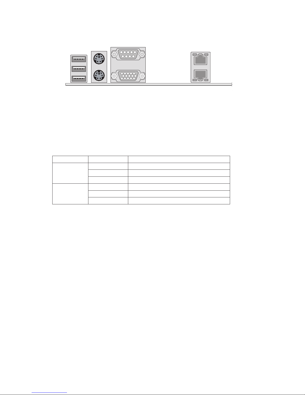
Back Panel Connectors
A. USB 1, 2, 3 D. Video
B. Mouse (top), Keyboard (bottom)
E. NIC 2 (1 GB)
C. Serial A F. NIC 1 (1 GB)
The NIC LEDs at the right and left of each NIC provide the following information.
Table 1. NIC LEDs
LED Color LED State Description
Left LED Off
No network connection is in place
Solid Green
Network connection is in place
Blinking Green Transmit/receive activity
Right LED Off 10 Mbps connection (if left LED is on or blinking)
Solid Green 100 Mbps connection
Solid Amber 1000 Mbps connection
a
Figure 1. Back Panel Connectors
TP00663
A
B
C
D
E
F
9MAXDATA PLATINUM 5220 Server
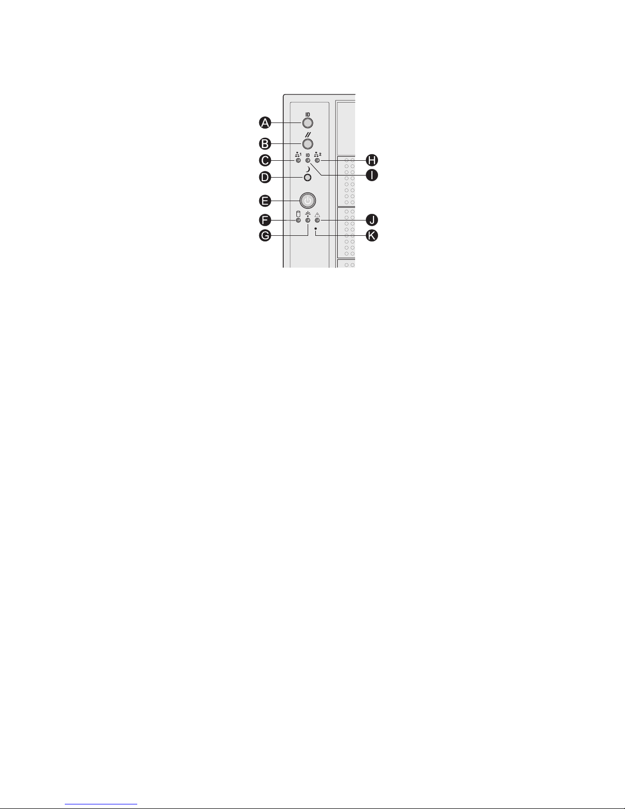
Front Panel Controls and Indicators
A. ID Toggle Switch G. Power/Sleep LED (green)
B. Reset Button
H. NIC 2 Activity LED (green)
C. NIC 1 Activity LED (green) I. ID LED (blue)
D. Sleep Button J.
Status LED (bi-color)
E. Power Button K. NMI Button
F. Hard Drive Activity LED (bi-color)
a
Figure 2. Pedestal Controls and Indicators

10 Setting up the System
Descriptions of the front panel LEDs are listed in the following table.
Table 2. Front Panel LED Description
LED Name Color Condition Description
Power/Sleep LED Green
ON Power On
Green
BLINK Standby/Sleep (S1)
OFF Off (also Sleep S4)
Status Green
ON System Ready
Green
BLINK System ready, but degraded: some CPU fault, DIMM killed
Amber ON Critical alarm: Critical power module failure, critical fan
failure, voltage (power supply), voltage and thermal fault
Amber BLINK Non-critical failure: Redundant fan failure, redundant power
failure, non-critical power and voltage
OFF System not ready: Post error / NMI event / PCI or terminator
missing
Hard Drive
Activity
Green
BLINK Hard drive activity
Amber ON Fault
OFF No activity
NIC 1 Activity Green
ON Linked
Green
BLINK LAN activity
OFF Idle
NIC 2 Activity Green
ON Linked
Green
BLINK LAN activity
OFF Idle
ID LED (rack
only)
Blue BLINK Server identification; Toggled by ID button or software
OFF Server identification; Toggled by ID button or software
11MAXDATA PLATINUM 5220 Server
2 Chassis Description
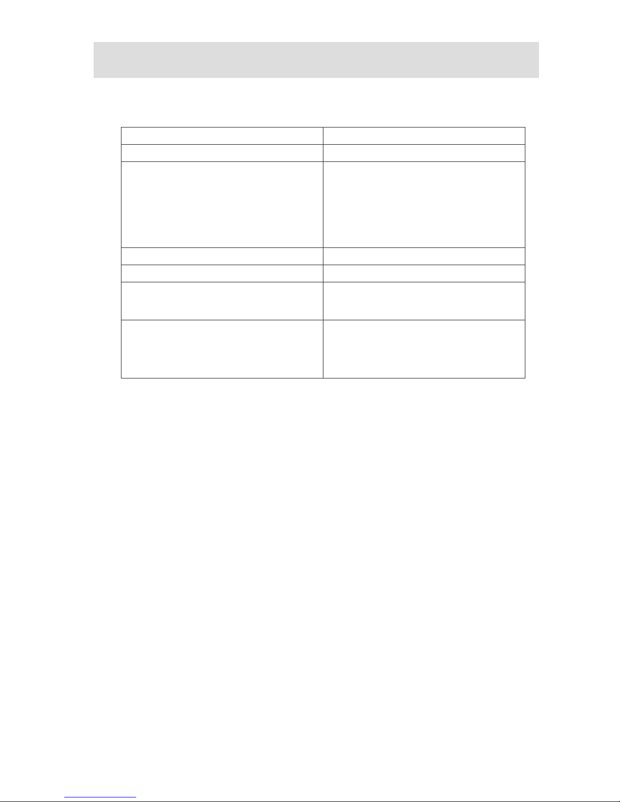
Feature Summary
Table 3. Feature Summary
Feature Description
Peripheral Bays
3 multi-mount 5.25 peripheral bays
Drive Bays
(6 + 4)
bay layout
One hot-swap drive bay for up to six SCSI
drives.
Optional hot-swap drive bay for up to four SCSI
drives.
Supports up to 10 drives
Expansion Slots Six full-length PCI expansion slots are available.
Form Factor 5U Tower, convertible to rack mount
Power Delivery
One redundant 730-W power supply with an
integrated cooling fan. Optional second redundant power supply is available.
Cooling Four hot-swap, redundant chassis fans:
• 2 120-mm fans
• 2 92-mm fans
Note: You need to install an Intel
®
management
module for the fans to be redundant.
12 Chassis Description
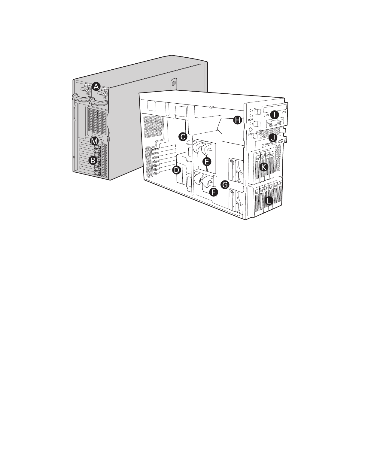
Chassis Front View
A. Power supply
B. PCI Add-in Card Panel
C. I/O Ports
D.
Air duct
E. 120-mm hot-swap, redundant chassis fans
F. 92-mm hot-swap, redundant chassis fans
G. Drive cage release mechanisms
H. Front panel controls and indicators
I. Three 5.25-inch removable media drive bays
J. Front Panel USB/Serial B
K. Hot Swap Drive Cage – 4 Drive (optional)
L. Hot Swap Drive Cage – 6 drive
M. ICBM or SCSI Knockout
a
Figure 3. MAXDATA PLATINUM 5220 Front View

13MAXDATA PLATINUM 5220 Server
Descriptions of the front panel LEDs are listed in the following table.
Table 4. Front Panel LED Descriptions
LED Name Color Condition Description
Power/Sleep LED
Green ON Power on
Green BLINK Standby/Sleep (S1)
OFF Off (also Sleep S4)
Status
Green ON System ready
Green BLINK System ready, but degraded: some CPU fault, DIMM
killed
Amber ON Critical alarm: Critical power module failure, critical
fan failure, voltage (power supply), voltage and
thermal fault
Amber BLINK Non-critical failure: Redundant fan failure, redundant
power failure, non-critical power and voltage
OFF System not ready: Post error/NMI event/PCI or termi-
nator missing
Hard drive activity
Green BLINK Hard drive activity
Amber ON Fault
OFF No activity
NIC1 activity Green ON Linked
Green BLINK LAN activity
OFF Idle
NIC2 activity Green ON Linked
Green BLINK LAN activity
OFF Idle
ID LED (rack only)
Blue BLINK Server identification; Toggled by ID button or soft-
ware
OFF Server identification; Toggled by ID button or soft-
ware
14 Chassis Description
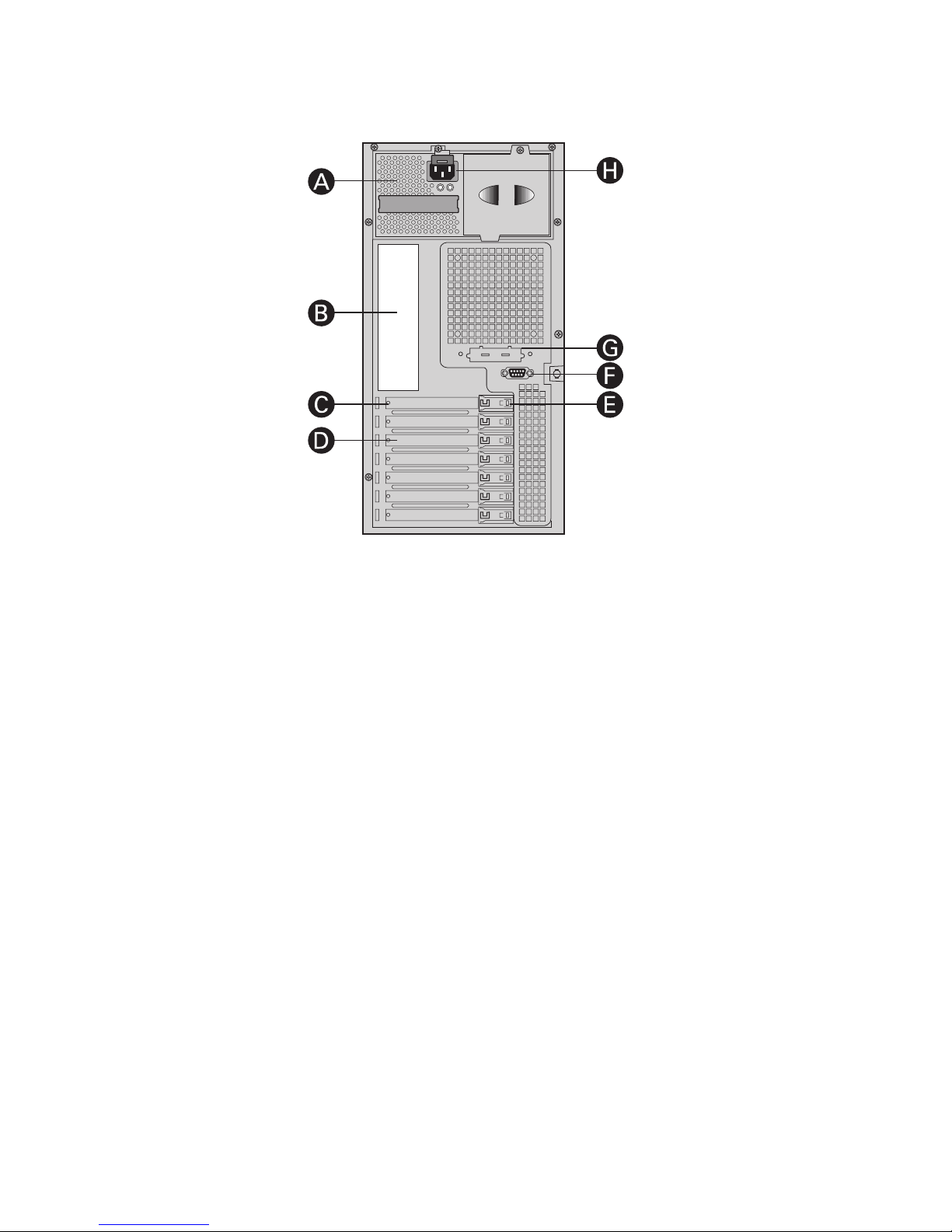
Chassis Rear View
A. Removable Power Supply
B. I/O Ports
C. Expansion Slot Covers
D. PCI Add-in Card Panel
E. PCI Card Latch
F. Rear Serial B Connector
G. ICBM or SCSI Knockout
H. AC Power Connector
Peripherals
5.25-in Half-height Peripheral Bays
Note: One multi-purpose 5.25-in drive carrier is included with the chassis. This drive carrier can hold
either a floppy drive (by removing the knock-out) or a fixed drive.
The upper bays of the server chassis are designed for removable media peripherals. Three 5.25-in,
half-height drive bays are available for floppy, CD-ROM or tape drives.
a
Figure 4. MAXDATA PLATINUM 5220 Chassis Rear View

15MAXDATA PLATINUM 5220 Server
3 Setting up the Chassis
This chapter describes how to set up your server chassis for the first time.
Tools and Supplies Needed
• Phillips (cross head) screwdriver (#2 bit)
• Small flat-head screwdriver
• Anti-static wrist strap (recommended)
Safety: Before You Remove the Access Cover
Before removing the access cover for any reason, observe these safety guidelines:
• Turn off all peripheral devices connected to the server.
• Turn off the server by pressing the power button on the front of the chassis. Then unplug the
AC power cord from the chassis or wall outlet.
• Label and disconnect all peripheral cables and all telecommunication lines connected to I/O
connectors or ports on the back of the chassis.
• Provide some electrostatic discharge (ESD) protection by wearing an antistatic wrist strap
attached to chassis ground – any unpainted metal surface – when handling components.
Warnings and Cautions
These warnings and cautions apply whenever you remove the access cover(s) to access components
inside the server. Only a technically qualified person should integrate and configure the server.
WARNINGS
The power button on the front panel DOES NOT turn off the AC power. To remove power from server,
you must unplug the AC power cord from the wall outlet or the chassis.
Hazardous electrical conditions may be present on power, telephone, and communication cables.
Turn off the server and disconnect the power cords, telecommunications systems, networks, and
modems attached to the server before opening it. Otherwise, personal injury or equipment damage
can result.
Hazardous voltage, current, and energy levels are present inside the power supply. There are no userserviceable parts inside it; servicing should be done by technically qualified personnel.
CAUTIONS
ESD can damage disk drives, boards, and other parts. Perform all procedures in this chapter only at
an ESD workstation. If one is not available, provide some ESD protection by wearing an antistatic
wrist strap attached to chassis ground – any unpainted metal surface – on your server when handling
parts.
Always handle boards carefully. They can be extremely sensitive to ESD. Hold boards only by their
edges. Do not touch the connector contacts. After removing a board from its protective wrapper or
from the server, place the board component side up on a grounded, static free surface. If you place
the server board on a conductive surface, the battery leads may short out. If they do, this will result
in a loss of CMOS data and will drain the battery. Use a conductive foam pad if available. Do not slide
board over any surface.
For proper cooling and airflow, always install the access cover before turning on the server. Operating
it without the cover in place can damage system parts.
 Loading...