


User’s Manual
MAXDATA Server PLATINUM 3200 I

2 3MAXDATA Server PLATINUM 3200 I M7Contents

Contents
1 Setting up the System 7
Server Position ........................................................................................................................................7
Back Panel Features ................................................................................................................................8
Front Panel Controls and Indicators ........................................................................................................9
2 Chassis Description 11
Feature Summary ..................................................................................................................................11
Base – Chassis Front View ....................................................................................................................12
Redundant Power – Chassis Front View ...............................................................................................13
Chassis Rear View .................................................................................................................................14
Peripherals .............................................................................................................................................14
5.25-inch Halfheight Peripheral Bays ................................................................................................14
3 Setting up the Chassis 15
Tools and Supplies Needed ...................................................................................................................15
Safety: Before You Remove the Access Cover .....................................................................................15
Warnings and Cautions .........................................................................................................................15
Remove Primary Access Cover .............................................................................................................16
Remove Bezel Assembly ......................................................................................................................16
Install 3.5-inch Floppy, DVD, or CD-ROM Drive ....................................................................................17
Install Fixed Hard Drive(s) ......................................................................................................................18
Install Hot Swap Drive(s) ....................................................................................................................... 20
4 Server Board Features 23
Connector and Header Locations .......................................................................................................... 24
Configuration Jumpers .......................................................................................................................... 25
Light-Guided Diagnostics ......................................................................................................................27
RAID Support ........................................................................................................................................28
Hardware Requirements .......................................................................................................................28
Processor .........................................................................................................................................28
System memory ...............................................................................................................................28
Memory Mirroring ............................................................................................................................30
Optional Hardware ................................................................................................................................30
Remote Management Module .........................................................................................................30
5 Hardware Installations and Upgrades 31
Before You Begin ..................................................................................................................................31
Tools and Supplies Needed ...................................................................................................................31
Installing and Removing Memory ..........................................................................................................31
Installing DIMMs ..............................................................................................................................31
Installing or Replacing the Processor ....................................................................................................32
Installing the Processor ....................................................................................................................32
Installing the Heatsink(s) ..................................................................................................................34
Removing a Processor .....................................................................................................................34
Installing or Removing a PCI Card ......................................................................................................... 34
Replacing the Backup Battery ...............................................................................................................35
Clearing the Password ..........................................................................................................................37
Recovering BIOS Defaults .....................................................................................................................38

4 5MAXDATA Server PLATINUM 3200 I M7Contents
6 Server Utilities 39
Using the BIOS Setup Utility ................................................................................................................. 39
Starting Setup ...................................................................................................................................39
If You Cannot Access Setup .............................................................................................................39
Setup Menus .................................................................................................................................... 39
7 Technical Reference 41
Power Supply Specifications ................................................................................................................. 41
670-W Single Power Supply Input Voltages ..................................................................................... 41
670-W Single Power Supply Output Voltages .................................................................................. 41
750 W Redundant Power Supply Input Voltages .............................................................................41
Efficiency .......................................................................................................................................... 41
750 W Redundant Power Supply Output Voltages ..........................................................................41
System Environmental Specifications ...................................................................................................42
8 Regulatory and Integration Information 43
Product Regulatory Compliance ............................................................................................................ 43
Product Safety Compliance ..............................................................................................................43
Product EMC Compliance ...............................................................................................................43
Product Regulatory Compliance Markings .......................................................................................43
Product RoHS Compliance ...............................................................................................................43
Installation Precautions .........................................................................................................................43
Installation Requirements ......................................................................................................................44
Prevent Power Supply Overload ......................................................................................................44
Place Battery Marking ......................................................................................................................44
Use Only for Intended Applications .......................................................................................................44
Power and Electrical Warnings ..............................................................................................................44
Rack Mount Warnings ...........................................................................................................................45

Figures
1. Back Panel Connectors and LEDs .....................................................................................................8
2. Pedestal Controls and Indicators ....................................................................................................... 9
3. MAXDATA PLATINUM 3200 I Base – Overview .............................................................................12
4. MAXDATA PLATINUM 3200 I Redundant Power – Overview ........................................................ 13
5. MAXDATA PLATINUM 3200 I Base – Chassis Rear View ..............................................................14
6. Removing the Access Cover ...........................................................................................................16
7. Removing Bezel Assembly ..............................................................................................................16
8. Removing Slide/Filler Panel Assembly from Upper Device Bay ...................................................... 17
9. Installing Slides on 3.5-inch Floppy Drive ........................................................................................17
10. Installing a DVD or CD-ROM Drive ..................................................................................................17
11. Removing Six-drive Fixed Drive Cage from Chassis .......................................................................18
12. Unlocking and Opening Upper Drive Cage Door .............................................................................18
13. Remove Slides from Drive Cage Door ............................................................................................19
14. Installing Device Slides to Hard Drive .............................................................................................19
15. Inserting Drive/Slide Assembly into Drive Cage ..............................................................................19
16. Releasing Drive Carrier from Hot Swap Cage .................................................................................20
17. Removing Plastic Retention Device ................................................................................................20
18. Securing Hard Drive to Drive Cage ..................................................................................................21
19. Inserting Drive Carrier into Drive Cage ............................................................................................21
20. Server Board Connector and Component Locations .......................................................................24
21. Configuration Jumpers .................................................................................................................... 25
22. Diagnostic LEDs .............................................................................................................................. 27
23. DIMM Sockets ................................................................................................................................29
24. Opening the Processor Socket ........................................................................................................32
25. Opening Load Plate ......................................................................................................................... 32
26. Removing protective covering from the load plate .........................................................................33
27. Inserting the processor ...................................................................................................................33
28. Close and lock load plate .................................................................................................................33
29. Preparing the Chassis for PCI Card Installation ...............................................................................34
30. Replacing the Backup Battery .........................................................................................................36
31. Password Clear Jumper ..................................................................................................................37
32. BIOS Defaults Jumper ...................................................................................................................38
Tables
1. NIC LEDs ........................................................................................................................................... 8
2. Description of Front Panel LEDs .....................................................................................................10
3. Feature Summary ............................................................................................................................ 11
4. Server Board Features .....................................................................................................................23
5. Keyboard Commands ......................................................................................................................40
6. 670-W Power Supply System Output Capability ............................................................................. 41
7. Efficiency of the Power Supply .......................................................................................................41
8. 750 W Power Supply Output Rating ...............................................................................................41
9. Environmental Specifications ..........................................................................................................42
10. Product Certification Markings ........................................................................................................43

6
7MAXDATA Server PLATINUM 3200 I M7
1 Setting up the System
Server Position
Please take note of the following criteria for creating a practical and safe workplace when setting up
your computer:
The system can be used anywhere the temperature is suitable for people. However, rooms
with humidity over 70 %, and dusty or dirty areas are not appropriate. In addition, do not
expose the server to any temperatures over +30 °C or under +10 °C.
Make sure that the cables connecting the server to peripheral devices are not tight.
Make sure that all power and connection cables are positioned so that they are not trip
hazards.
When you save data to your server‘s hard disks or to a floppy disk, they are stored as
magnetic information on the media. Make sure that they are not damaged by magnetic or
electromagnetic fields.
Because the electronics in your computer can be damaged by jarring, no mechanical devices
should be placed on the same surface as the server. This is especially important for impact
printers whose vibrations could damage the hard disk.
Please take care to ensure a free air flow to the server at all times. Do not block the ventilation
slots of the server case and particularly the power supplies. An insufficient air flow may
damage the server and / or it’s components.
ATTENTION
In order to fully separate the server from current, the power cord(s) must be removed from the wall
outlet.
8 Setting up the System
Back Panel Features
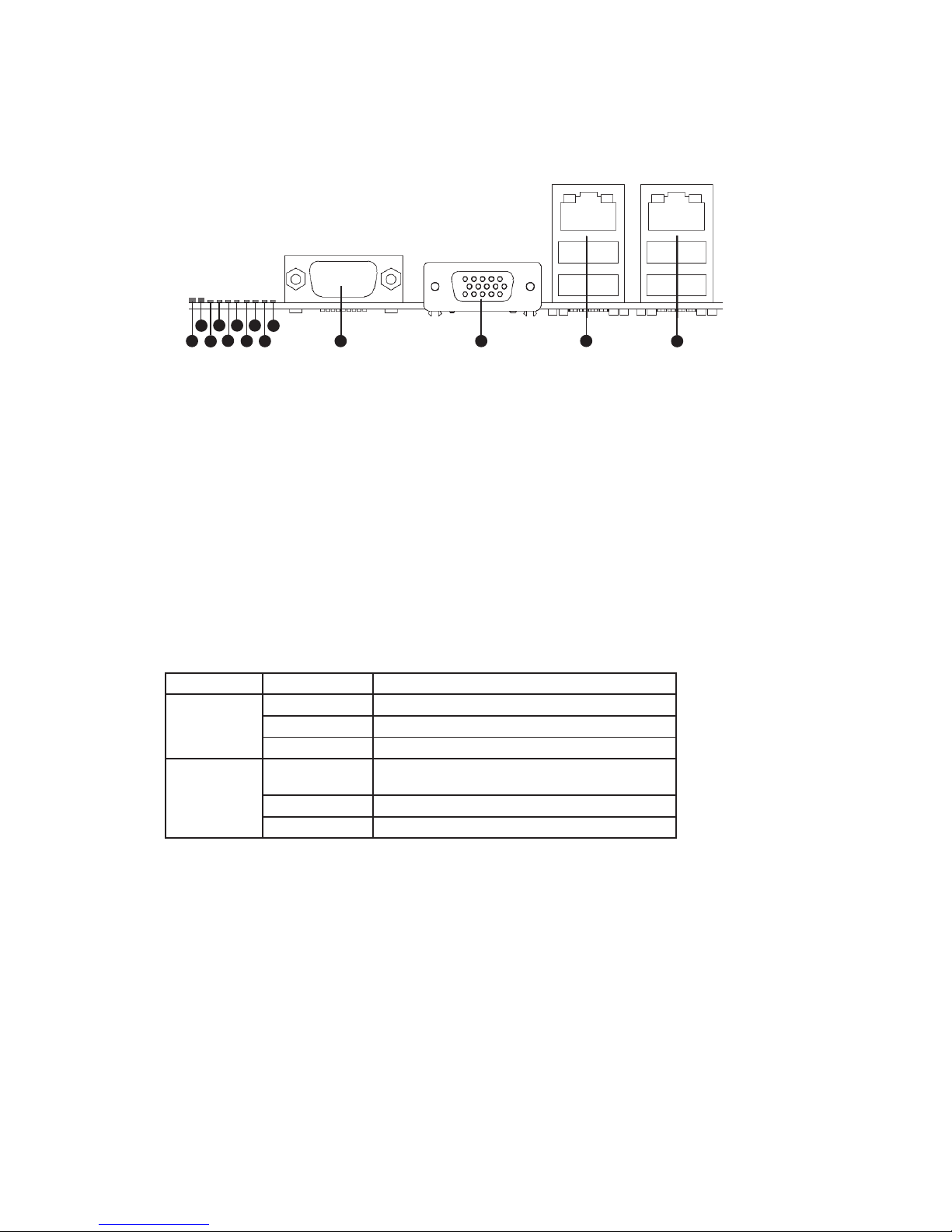
The diagram and table show the back panel connectors and LEDs. For information about LEDs, see
“Light-Guided Diagnostics” on page 27.
Figure 1. Back Panel Connectors and LEDs
A. Status LED H. Diagnostic LED 2
B. System Identification LED I. Diagnostic LED 1
C. Diagnostic LED 7 (MSB LED) J. Diagnostic LED 0 (LSB LED)
D. Diagnostic LED 6 K. Serial Port A
E. Diagnostic LED 5 L. Video Port
F. Diagnostic LED 4 M. NIC 1 (top, default management port),
two USB ports (bottom)
G. Diagnostic LED 3 N. NIC 2 (top), two USB ports (bottom)
The NIC LEDs at the right and left of each NIC provide the following information.
Table 1. NIC LEDs
LED Color LED State Description
Left LED Off No network connection is in place
Solid Green Network connection is in place
Blinking Green Transmit/receive activity is occurring
Right LED Off 10 Mbps connection (if left LED is on or
blinking)
Solid Green 100 Mbps connection
Solid Amber 1000 Mbps connection
A
B
D
F
C
E
G
H
I
J
K L
M
N
9MAXDATA Server PLATINUM 3200 I M7
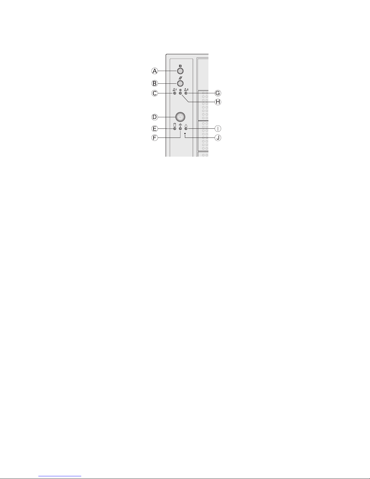
Front Panel Controls and Indicators
Figure 2. Pedestal Controls and Indicators
A. ID Toggle Switch F. Power/Sleep LED (green)
B. Reset Button G. NIC 2 Activity LED (green)
C. NIC 1 Activity LED (green) H. ID LED (blue)
D. Power Button I. Status LED (bi-color)
E. Hard Drive Activity LED (green) J. NMI Button
10 Setting up the System
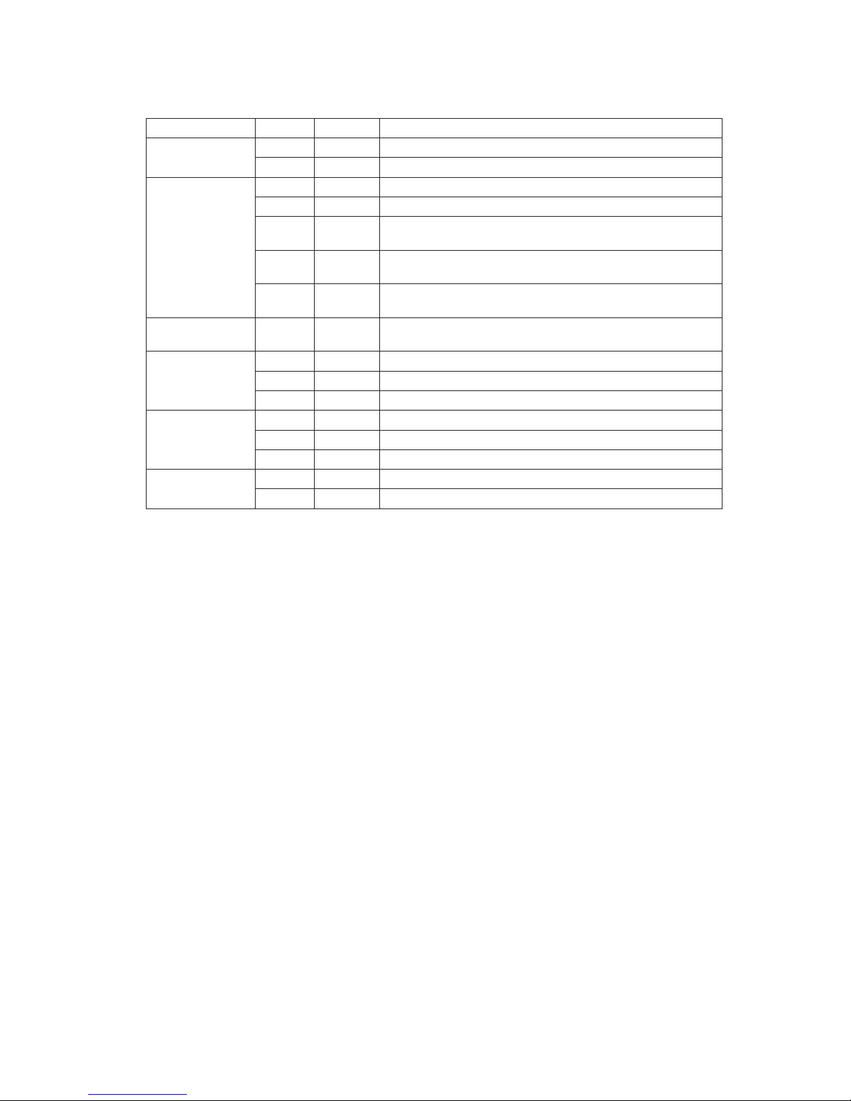
Descriptions of the front panel LEDs are listed in the following table.
Table 2. Description of Front Panel LEDs
LED Name Color Condition Description
Power/Sleep LED Green ON Power On
OFF Off
Status Green ON System Ready
Green BLINK System ready, but degraded: some CPU fault, DIMM killed
Amber ON Critical alarm: Critical power module failure, critical fan
failure, voltage (power supply), voltage and thermal fault
Amber BLINK Non-critical failure: Redundant fan failure, redundant power
failure, non-critical power and voltage
OFF AC power off; powered down (DC-off state or S5), and no
degraded, non-critical, critical conditions exist*
Hard Drive
Activity
Green BLINK Hard drive activity
NIC 1 Activity Green ON Linked
Green BLINK LAN activity
OFF Idle
NIC 2 Activity Green ON Linked
Green BLINK LAN activity
OFF Idle
ID LED (rack
only)
Blue BLINK Server identification; Toggled by ID button or software
OFF Server identification; Toggled by ID button or software
* When the server is powered down (transitions to the DC-off state or S5), the BMC is still on
standby power and retains the sensor and front panel status LED state established before the
power-down event. If the system status is normal when the system is powered down (the
LED is in a solid green state), the system status LED will be off.
11MAXDATA Server PLATINUM 3200 I M7
2 Chassis Description
Feature Summary
Table 3. Feature Summary
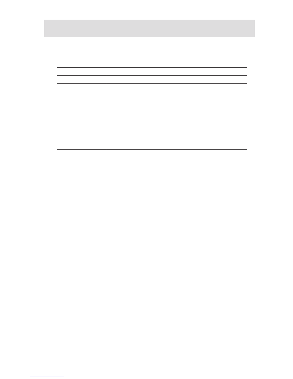
Feature P3200 I Description
Peripheral Bays 3 multi-mount 5.25 peripheral bays
Drive Bays (6 + 4) bay
layout
One fixed drive bay for up to 6 hard drives
Optional: Hot swap drive bay
• for 6 hard drives (SAS/SATA)
• for 4 hard drives (SAS/SATA)
• P3200 I Base: up to 6 drives
P3200 I Redundant: up to 10 drives
Expansion Slots Six full-length PCI expansion slots are available.
Form Factor 5U Tower, convertible to rack mount
Power Delivery a) P3200 I Base: One fixed 670-W power supply with an integrated fan
b) P3200 I Redundant Power: Two highly efficient, redundant 750-W
hot swap power supplies with an integrated fan
Cooling a) P3200 I Base: Three fixed, non-redundant chassis fans
• Two 120-mm fans: one at the front and one at the rear
• One 92-mm fan at the front
b) P3200 I Redundant: Four hot-swap, redundant chassis fans:
• Two 120 mm and two 92 mm fans at the front

12 Chassis Description
Base – Chassis Front View
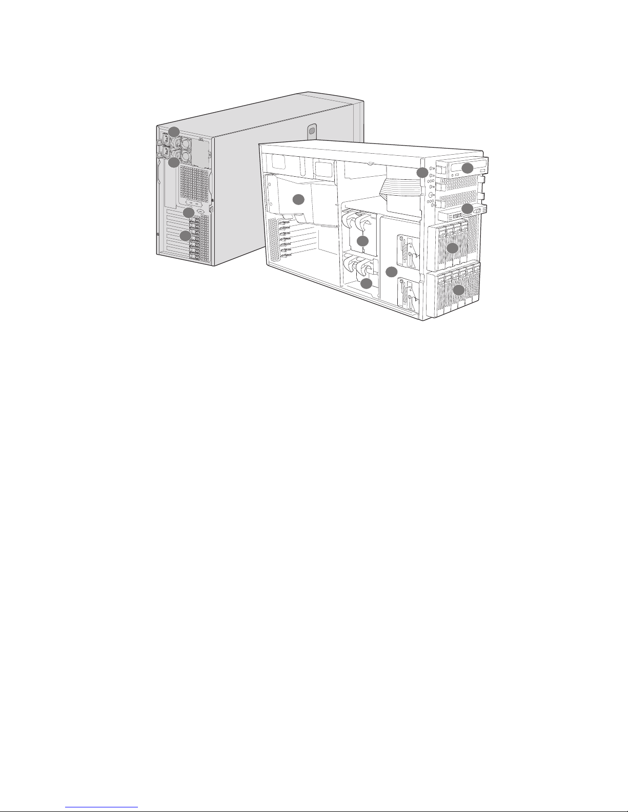
Figure 3. MAXDATA PLATINUM 3200 I Base – Overview
A. Fixed Power Supply
B. Rear Serial Port B
C. PCI Add-in Card Panel
D. Air Duct and Fixed Fan (rear)
E. 2 Fixed Fans (front)
F. 2 Hard Drive Cage Release Mechanisms
G. Front Control Panel
H. 5.25-inch Device Bay
I. Front Panel USB / Serial B
J. Hard Drive Cage – 4 Drive (accessory)
K. Hard Drive Cage – 6 Drive
A
B
C
D
E
F
G
H
I
J
K
13MAXDATA Server PLATINUM 3200 I M7
Redundant Power – Chassis Front View
Figure 4. MAXDATA PLATINUM 3200 I Redundant Power – Overview
A. Hot Swap Power Supply 1
B. Hot Swap Power Supply 2
C. Rear Serial Port B
D. PCI Add-in Card Panel
E. Air Duct
F. 2 Large Hot Swap Fans
G. 2 Small Hot-swap Fans
H. 2 Hard Drive Cage Release Mechanisms
I. Front Control Panel
J. 5.25-inch Device Bay
K. Front Panel USB / Serial B
L. Hard Drive Cage – 4 Drive (accessory)
M. Hard Drive Cage – 6 Drive (accessory)
A
B
C
D
E
F
G
H
I
J
K
L
M
14 Chassis Description
Chassis Rear View
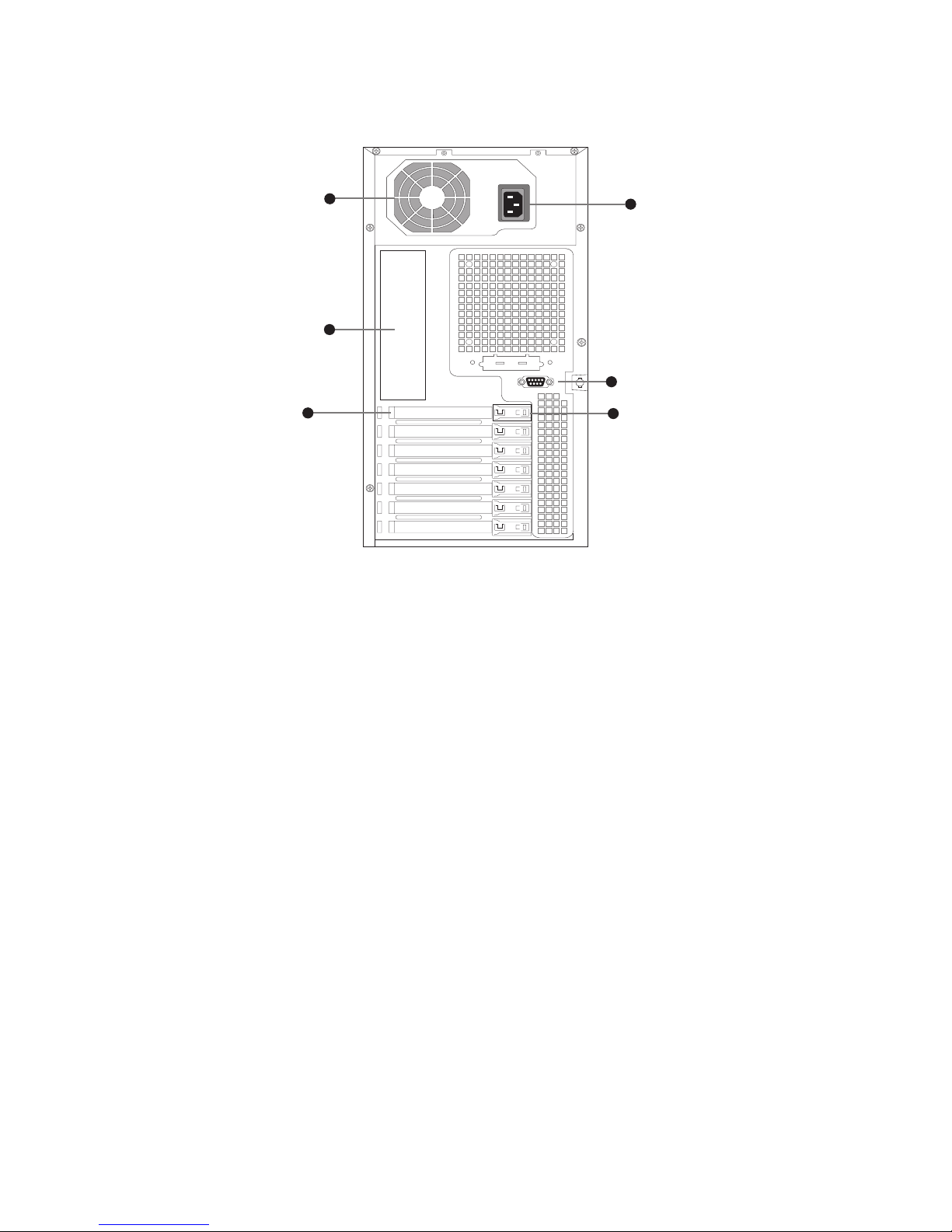
Figure 5. MAXDATA PLATINUM 3200 I Base – Chassis Rear View
A. Power supply
B. I/O Ports
C. Expansion Slot Covers
D. PCI Card Latch
E. Rear Serial B Connector (optional)
F. AC Power Connector
Peripherals
5.25-inch Halfheight Peripheral Bays
The upper bays of the server chassis are designed for removable media peripherals. Three 5.25-inch,
half-height drive bays are available for floppy, CD-ROM or tape drives.
NOTE
One multi-purpose 5.25-inch drive carrier is included with the chassis. This drive carrier can hold either
a 3.5 inch drive (by removing the knockout) or a fixed drive.
C
E
D
F
B
A
 Loading...