


User’s Manual
MAXDATA Server PLATINUM 2200 IR

2

3MAXDATA Server PLATINUM 2200 IR M7
Contents
1 Setting up the System 7
Server Position ........................................................................................................................................7
Connecting the System ...........................................................................................................................8
Rear of Server System .......................................................................................................................8
Standard Control Panel ............................................................................................................................9
Local Control Panel ................................................................................................................................10
2 Server System Features 11
Connector and Header Locations .......................................................................................................... 12
Configuration Jumpers .......................................................................................................................... 13
Light Guided Diagnostics ......................................................................................................................14
RAID Support ........................................................................................................................................15
Hardware Requirements .......................................................................................................................15
Processor .........................................................................................................................................15
System Memory ...............................................................................................................................15
Available memory modules ..............................................................................................................17
Memory Mirroring ............................................................................................................................17
Optional Hardware ................................................................................................................................17
Remote Management Module .........................................................................................................17
Add-in I/O modules ...........................................................................................................................17
3 Server Chassis Features 19
Component Identification ...................................................................................................................... 19
Internal Components ........................................................................................................................ 19
SAS/SATA Mid-Planes ...........................................................................................................................20
Hot-Swap SAS/SATA Backplane ...........................................................................................................21
Peripheral Devices .................................................................................................................................22
4 Hardware Installations and Upgrades 23
Before You Begin ..................................................................................................................................23
Tools and Supplies Needed .............................................................................................................. 23
System References .......................................................................................................................... 23
Removing and Installing the Chassis Cover ..........................................................................................23
Removing and Installing the Front Bezel ...............................................................................................24
Removing the Front Bezel ................................................................................................................ 24
Installing the Front Bezel .................................................................................................................. 24
Installing a SAS or SATA Hot-swap Hard Disk Drive .............................................................................25
Removing a Hot-swap Hard Disk Drive .................................................................................................26
Removing and Installing the PCI Riser Assembly .................................................................................27
Removing the PCI Riser Assembly ..................................................................................................27
Installing the PCI Riser Assembly ....................................................................................................27
Installing a PCI Add-in Card ..............................................................................................................28
Installing or Replacing a Hot-swap Power Supply .................................................................................29
Removing a Hot-swap Power Supply ............................................................................................... 29
Filling Empty Chassis Bays ....................................................................................................................29
Installing Memory ..................................................................................................................................30
DIMM Blank Population ...................................................................................................................30
Installing DIMMs ..............................................................................................................................30
Installing or Replacing the Processor ....................................................................................................31
Installing the Processor ....................................................................................................................31
Installing the Heat Sink(s) ................................................................................................................. 33
Removing a Processor .....................................................................................................................33
RJ45 Serial Port Configuration ..............................................................................................................34
Replacing the Backup Battery ...............................................................................................................35

4 Contents
5 Server Utilities 37
Using the BIOS Setup Utility ................................................................................................................. 37
Starting Setup ...................................................................................................................................37
If You Cannot Access Setup .............................................................................................................37
Setup Menus .................................................................................................................................... 37
Clearing the Password ..........................................................................................................................39
Recovering BIOS Defaults .....................................................................................................................39
6 Troubleshooting 41
LED Information ....................................................................................................................................41
7 Technical Reference 43
Power Supply Specifications ................................................................................................................. 43
750-W Single Power Supply Input Voltages ..................................................................................... 43
Efficiency .......................................................................................................................................... 43
750-W Single Power Supply Output Voltages .................................................................................. 43
System Environmental Specifications ...................................................................................................43
8 Regulatory and Integration Information 45
Product Regulatory Compliance ............................................................................................................ 45
Product Safety Compliance ..............................................................................................................45
Product EMC Compliance ...............................................................................................................45
Product Regulatory Compliance Markings .......................................................................................45
Product RoHS Compliance ...............................................................................................................45
Installation Precautions .........................................................................................................................45
Use Only for Intended Applications .......................................................................................................46
Power and Electrical Warnings ..............................................................................................................46
Rack Mount Warnings ...........................................................................................................................46

5MAXDATA Server PLATINUM 2200 IR M7
Figures
1. Server System Back ..........................................................................................................................8
2. Standard Control Panel ...................................................................................................................... 9
3. Local Control Panel..........................................................................................................................10
4. Server Board Connector and Component Locations .......................................................................12
5. Configuration Jumpers ....................................................................................................................13
6. Light Guided Diagnostic LEDs .........................................................................................................14
7. Diagram of DIMM configuration ......................................................................................................15
8. Mapping of DIMM sockets .............................................................................................................16
9. Internal Component Locations ........................................................................................................19
10. Passive Mid-Plane Components ......................................................................................................20
11. Active SAS/SATA Mid-Plane Components ......................................................................................20
12. Hot-Swap SAS/SATA Backplane Components (Front View) ...........................................................21
13. Hot-Swap SAS/SATA Backplane Components (Rear View) ............................................................21
14. Optional Peripherals ........................................................................................................................22
15. Removing the Chassis Cover ..........................................................................................................23
16. Removing the Front Bezel ...............................................................................................................24
17. Removing the Hot-swap Hard Drive Carrier from the Chassis ........................................................25
18. Removing the Retention Device from the Hot-swap Drive Carrier .................................................25
19. Attaching a Hot-swap Hard Disk Drive to a Drive Carrier ................................................................26
20. Removing the PCI Riser Assembly from the Chassis .....................................................................27
21. Installing a PCI Add-in Card .............................................................................................................28
22. Removing a Hot-swap Power Supply ..............................................................................................29
23. Installing Memory ............................................................................................................................30
24. Lifting the Processor Socket Handle ...............................................................................................31
25. Lifting the load plate ........................................................................................................................31
26. Removing protective covering from the load plate .........................................................................32
27. Inserting the processor ...................................................................................................................32
28. Close and lock load plate .................................................................................................................32
29. Installing Heat Sink (2U Heat Sink shown) ......................................................................................33
30. Changing the Serial Port Configuration ...........................................................................................34
31. Replacing the Backup Battery .........................................................................................................36
Tables
1. NIC LEDs ...........................................................................................................................................8
2. Standard Control Panel Features ....................................................................................................... 9
3. Local Control Panel Features ...........................................................................................................10
4. Server System Features .................................................................................................................. 11
5. Keyboard Commands ......................................................................................................................38
6. LED Information ..............................................................................................................................41
7. Efficiency of the power supply ........................................................................................................ 43
8. 750-W Power Supply System Output Capability ............................................................................. 43
9. Environmental Specifications ..........................................................................................................43
10. Product Certification Markings ........................................................................................................45

6
7MAXDATA Server PLATINUM 2200 IR M7
1 Setting up the System
Server Position
Please take note of the following criteria for creating a practical and safe workplace when setting up
your computer:
The system can be used anywhere the temperature is suitable for people. However, rooms
with humidity over 70%, and dusty or dirty areas are not appropriate. In addition, do not
expose the server to any temperatures over +30 °C or under +10 °C.
Make sure that the cables connecting the server to peripheral devices are not tight.
Make sure that all power and connection cables are positioned so that they are not trip
hazards.
When you save data to your server‘s hard disks or to a floppy disk, they are stored as
magnetic information on the media. Make sure that they are not damaged by magnetic or
electromagnetic fields.
Because the electronics in your computer can be damaged by jarring, no mechanical devices
should be placed on the same surface as the server. This is especially important for impact
printers whose vibrations could damage the hard disk.
Please take care to ensure a free air flow to the server at all times. Do not block the ventilation
slots of the server case and particularly the power supplies. An insufficient air flow may
damage the server and / or it’s components.
ATTENTION
In order to fully separate the server from current, the power cord must be removed from the wall
outlet.
8 Setting up the System
Connecting the System
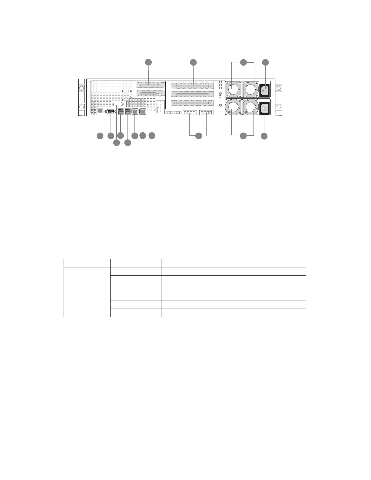
Rear of Server System
Figure 1. Server System Back
A. Low Profile Add-in Card Slots I. NIC 1
B. Full Height PCI Add-in Card Slots J. NIC 2
C. Upper Power Supply Module K. USB 6
D. Upper Power Receptacle L. USB 5
E. Lower Power Receptacle M. DB-9 Serial A Connector
F. Lower Power Supply Module (optional) N. Video
G. I/O Module (optional) O. RJ45 Serial B Connector
H. Server Management NIC (optional)
Table 1. NIC LEDs
LED Color LED State Description
Left LED Off No network connection
Solid Amber Network connection in place
Blinking Amber Transmit/receive activity
Right LED Off 10 Mbps connection (if left LED is on or blinking)
Solid Amber 100 Mbps connection
Solid Green 1000 Mbps connection
A
B
O N
L
KM
J
I H
GG F
E
F
C D
9MAXDATA Server PLATINUM 2200 IR M7
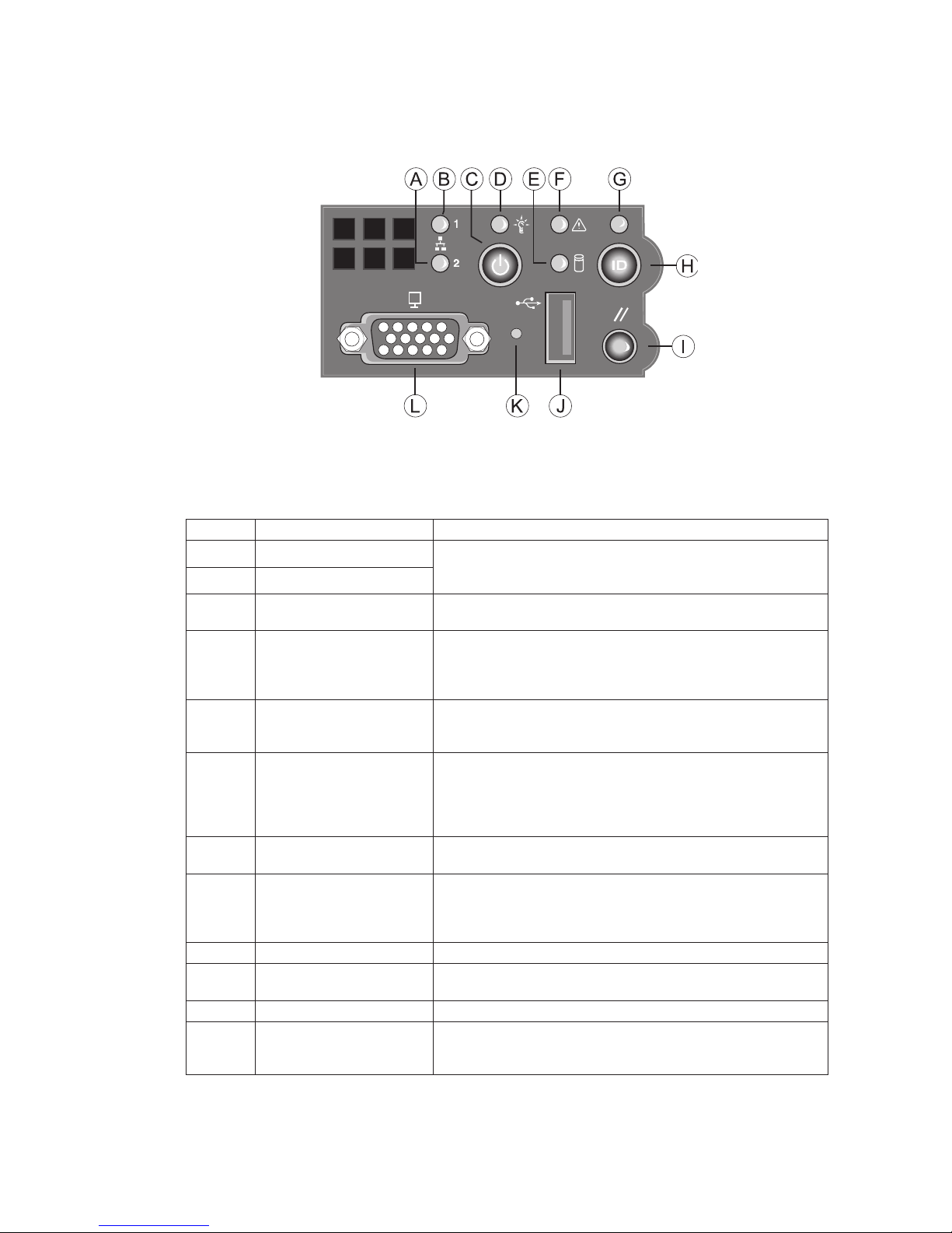
Standard Control Panel
The diagram below shows the features available on the Standard Control Panel. The Standard Control
Panel is one of two required control options that can be selected. The other option is the Local Control
Panel.
Figure 2. Standard Control Panel
Table 2. Standard Control Panel Features
Callout Feature Function
A. NIC 2 activity LED Continuous green light indicates a link between the system
and the network to which it is connected.
Blinking green light indicates network activity.
B. NIC 1 activity LED
C. Power/Sleep button Toggles the system power on/off. Sleep button for ACPI
compatible operating systems.
D. Power/Sleep LED Continuous green light indicates the system has power
applied to it. Blinking green indicates the system is in S1
sleep state.
No light indicates the power is off / is in ACPI S4 or S5 state.
E. Hard disk drive activity
LED
Random blinking green light indicates hard disk drive activity
(SCSI or SATA).
No light indicates no hard disk drive activity.
F. System Status LED Solid green indicates normal operation
Blinking green indicates degraded performance
Solid amber indicates a critical or non-recoverable condition
Blinking amber indicates a non-critical condition
No light indicates POST is running or the system is off.
G. System Identification LED Solid blue indicates system identification is active
No light indicates system identification is not activated
H. System Identification
button
Toggles the front panel ID LED and the baseboard ID LED
on and off. The baseboard LED is visible from the rear of the
chassis and allows you to locate the server from the rear of a
rack of systems.
I. Reset button Reboots and initializes the system.
J. USB 2.0 port Allows you to attach a USB component to the front of the
chassis.
K. NMI button Puts the server in a halt-state for diagnostic purposes.
L. Video port Allows you to attach a video monitor to the front of the
chassis. The front and rear video ports cannot be used at the
same time.
10 Setting up the System
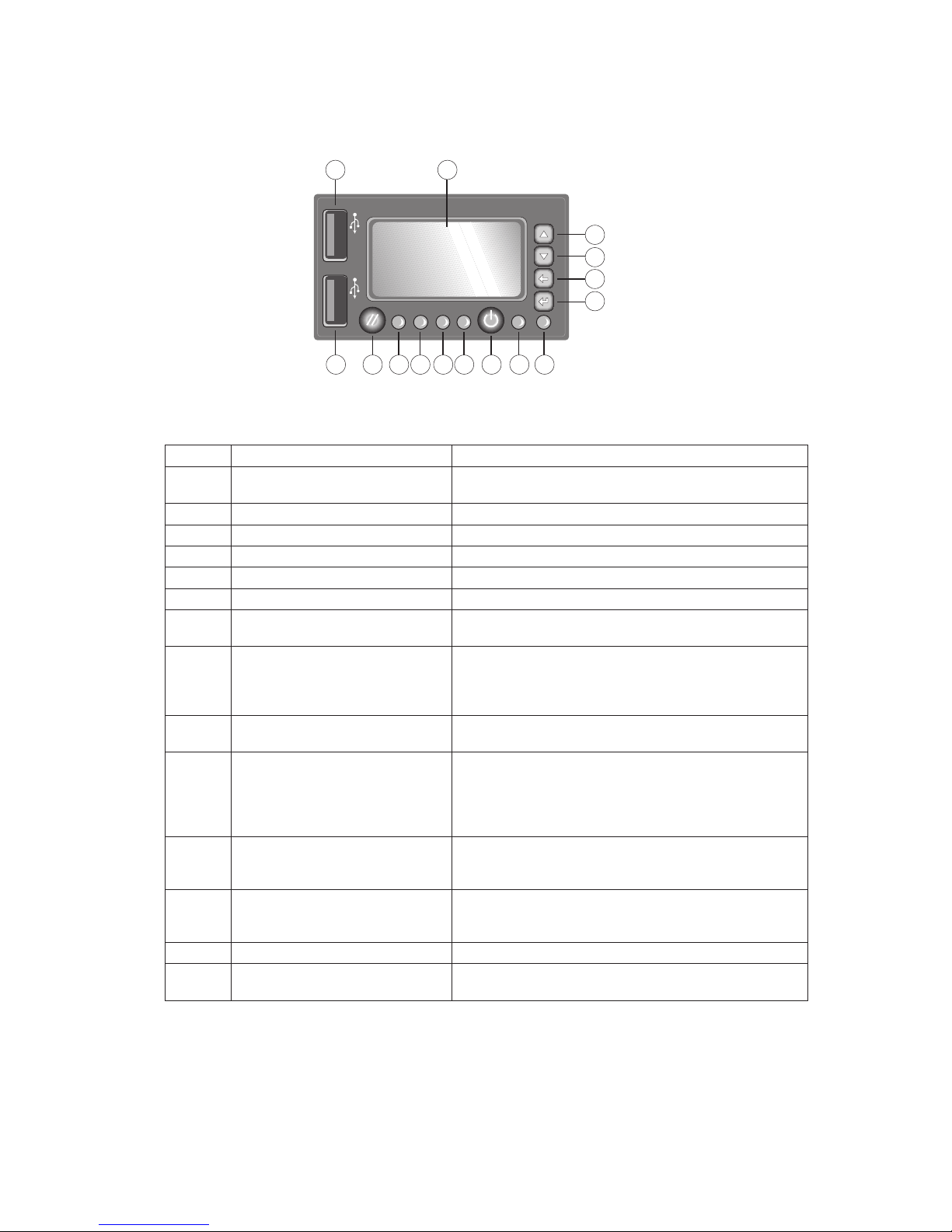
Local Control Panel
The diagram below shows the features available on the Local Control Panel. The Local Control Panel
is one of two required control options that can be selected.
Figure 3. Local Control Panel
Table 3. Local Control Panel Features
Callout Feature Function
A. USB 2.0 port Allows you to attach a USB component to the front of
the chassis.
B. LCD display Screen on which system information is displayed.
C. Menu control button, scroll up Scroll up one option at a time.
D. Menu control button, scroll down Scroll down one option at a time.
E. Menu control button, scroll left Move to the previous option.
F. Menu control button, enter Select option.
G. System Identification LED Solid blue indicates system identification is active. No
light indicates system identification is not activated.
H. Power/Sleep LED Continuous green light indicates the system has power
applied to it. Blinking green indicates the system is in
S1 sleep state. No light indicates the power is off / is in
ACPI S4 or S5 state.
I. Power/Sleep button Toggles the system power on/off. Sleep button for ACPI
compatible operating systems.
J. System Status LED Solid green indicates normal operation. Blinking green
indicates degraded performance. Solid amber indicates
a critical or non-recoverable condition. Blinking amber
indicates a non-critical condition. No light indicates
POST is running or the system is off.
L.
K.
NIC 1 activity LED
NIC 2 activity LED
Continuous green light indicates a link between the
system and the network to which it is connected.
Blinking green light indicates network activity.
M. Hard disk drive status LED Random blinking green light indicates hard disk drive
activity. No light indicates no hard disk drive activity is
taking place
N. Reset button Reboots and initializes the system.
O. USB 2.0 port Allows you to attach a USB component to the front of
the chassis.
11MAXDATA Server PLATINUM 2200 IR M7
2 Server System Features
This chapter briefly describes the main features of the MAXDATA PLATINUM Server System.
It provides a list of the server system features and diagrams showing the location of important
components and connections on the server system.
Table 4 summarizes the major features of the server system.
Table 4. Server System Features
Feature Description
Dimensions
• 87.30 mm high
• 430 mm wide
• 704.8 mm deep
• 29.5 kg max chassis weight
Server board Intel® S5520UR
Processor One or two Intel® Xeon® 5500 processors with a thermal design power (TDP)
of up to 95 W
System memory • 12 DIMM slots, 6 per processor, distributed over three memory channels
• Up to 96 GB system memory
• 800/1066/1333 MT/s ECC registered (RDIMM) or unbuffered (UDIMM) DDR3
memory
• No mixing of RDIMMs and UDIMMs
Chipset • Intel® 5520 Chipset IOH
• Intel® 82801Jx I/O Controller Hub (ICH10R)
Peripheral Interfaces External connections:
• One DB-15 graphics port
One RJ45 serial B port
• Two RJ45 network ports for 10/100/1000 Mbps
• Four USB 2.0 ports (back panel)
• One USB 2.0 port (front)
Internal connections:
• One USB connector for two USB 2.0 ports
• One DH10 connector for serial A port
• Six SATA II ports
• Two ports for optional I/O extensions (Dual 1 Gbit NIC/10 Gbit NIC/SAS)
• One port for an optional remote management module
Graphics On-board ServerEngines LLC Pilot II Controller with integrated 2D video
controller, 64 MB DDR2 memory, 8 MB of which is graphics memory
LAN One Intel® 82575EB controller with two ports for 10/100/1000 Mbps Ethernet
LAN
Expansion
capabilities
• Two PCIe x8 connectors on a low profile riser card
• Three PCIe x8 connectors on a full size riser card, one of them with x16
socket
Hard disk drives • Five hot-swap SATA/SAS hard disk drives
• Drive bay for sixth hot-swap SATA/SAS drive or 3.5-inch tape drive or two
fixed 2.5-inch hard disk drives
Peripheral devices Slimline floppy drive for optical SATA drive
Power supply One or two redundant power supplies with 750 W each
Fans • Six redundant hot-swap fans, 2 × 60 mm, 4 × 80 mm
• Two non-redundant fans in each power supply
Server management IPMI 2.0 compatible Light Guided Diagnostics
12 Server System Features
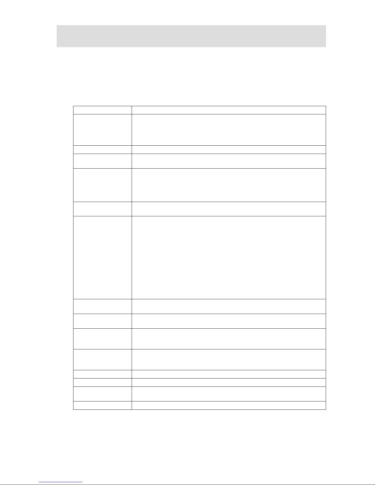
Connector and Header Locations
Figure 4. Server Board Connector and Component Locations
A. 280-pin Intel® Adaptive Riser Card slot Q. Fan board connector
B. POST code LEDs R. 2×4 power connector
C. Intel® RMM3 header S. Main power connector
D. Processor 1 T. Power supply SMBus connector
E. Back panel I/O U. Fan header
F. ID LED V. USB header
G. System status LED W. Solid state drive header
H. Fan header X. Fan header
I. Fan header Y. LCP IPMB header
J. Processor 1 DIMM slots Z. OEM IPMB header
K. Processor 2 DIMM slots AA. SGPIO header
L. Processor 2 BB. SATA connectors
M. Fan header CC. I/O module mezzanine connector 2
N. Fan header DD. I/O module mezzanine connector 1
O. Bridge board connector EE. Serial port B header
P. Front panel connector
EB C F GDA
EE
DD
CC
BB
AA
Z
Y
V
W
X
U
T
J
H
I
K
L
MNS R OPQ
13MAXDATA Server PLATINUM 2200 IR M7
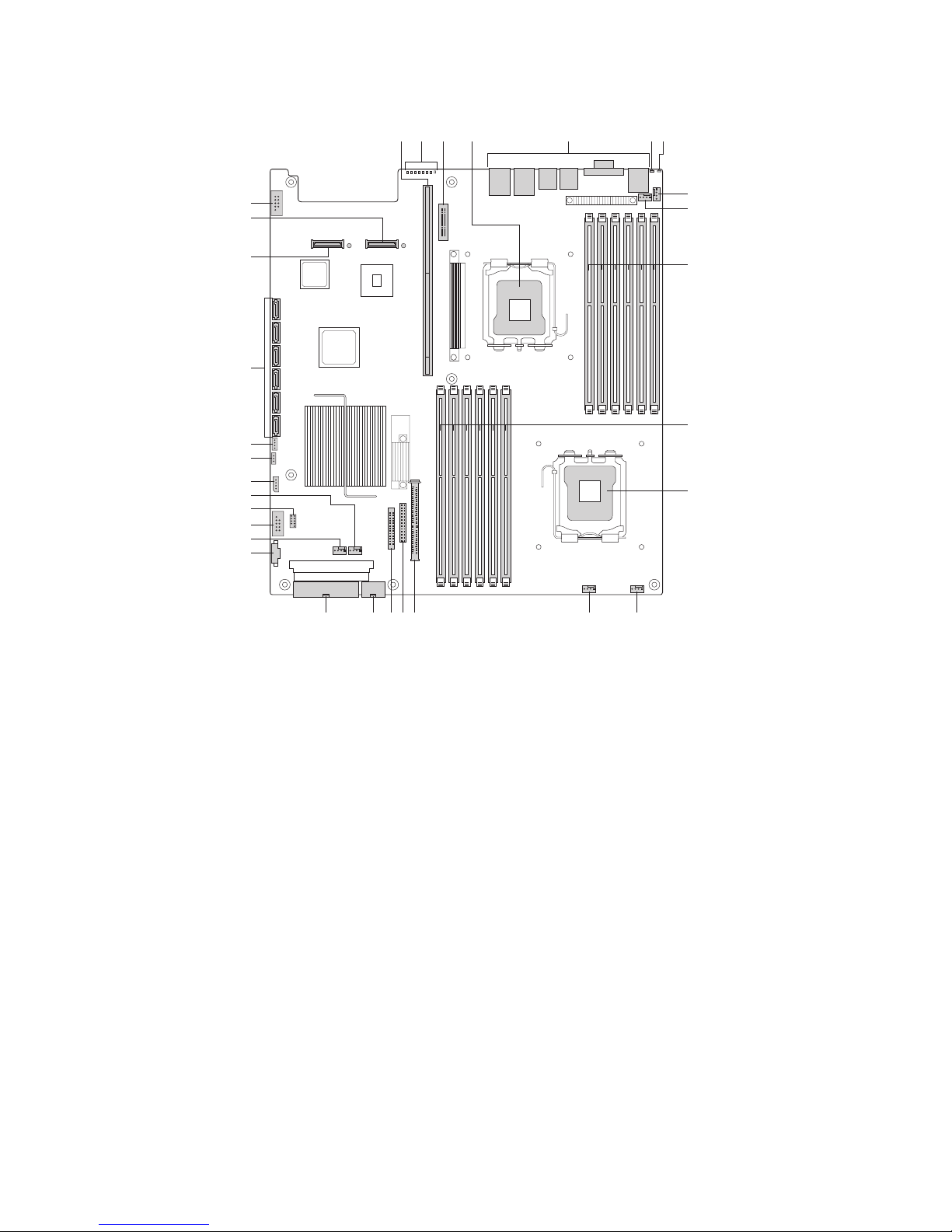
Configuration Jumpers
Figure 5. Configuration Jumpers
2
3
2
3
2
3
2
3
E
D
C
B
3 4
2
A
J1D4
BIOS Recovery
Normal
Recover
Protect
Clear
Enable
Disable
J1E8
Password Clear
J1E7
BIOS Default
J1H2
BMC Force Update
Normal
Set
Default
Serial Port
Configuration
J9A1
DSR to DTR
(factory default)
DCD to DTR
14 Server System Features
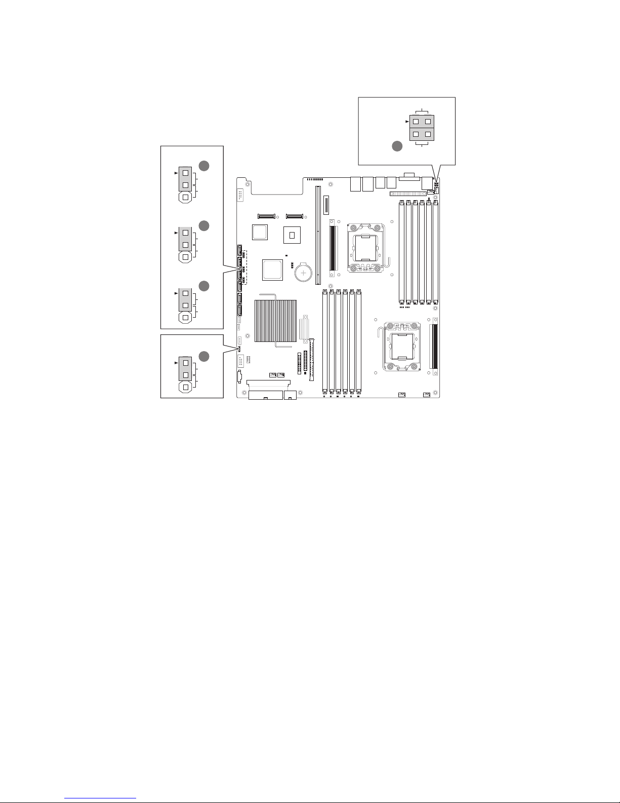
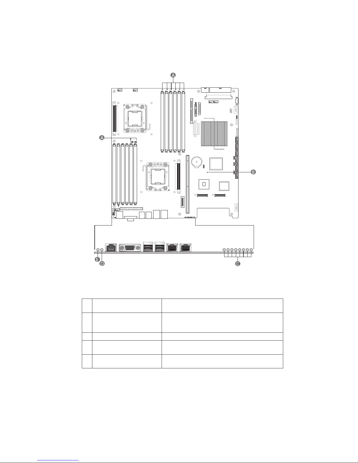
Light Guided Diagnostics
The server board contains diagnostic LEDs to help you identify failed and failing components, and to
help you identify the server from among several servers. Except for the ID LED, the status LED, and
the 5V standby LED, the LEDs turn on (amber) only if a failure occurs.
Figure 6. Light Guided Diagnostic LEDs
A. DIMM fault LEDs The DIMM fault LED identifies faults in the
assigned memory module
B. 5-volt standby LED The LED is labelled “5VSB_LED”. It lights up when
the server is supplied with power and the 5-volt
standby circuit of the mainboard is active.
C. POST code diagnostic LEDs Display BIOS-POST codes during system startup
D. System Identification LED This LED has the same function as the LED on the
system front panel (see Table 2, page 9).
E. System Status LED This LED displays the same status as the LED on
the system front panel (see Table 2, page 9).
 Loading...