


MAXDATA PLATINUM 200 I M6
User’s Manual

2 3MAXDATA PLATINUM 200 I M6Contents

Contents
1 Setting up the System 5
Safety Information ...................................................................................................................................5
Server Position ...................................................................................................................................5
System Access Warnings ..................................................................................................................6
Rack Mount Warnings ........................................................................................................................6
Powering up the System .........................................................................................................................7
2 Board Features 9
Connector and Header Locations ..........................................................................................................11
Configuration Jumpers ..........................................................................................................................12
Back Panel Connectors .........................................................................................................................13
Hardware Requirements .......................................................................................................................14
Memory ............................................................................................................................................14
3 Hardware Installations and Upgrades 15
Before You Begin ..................................................................................................................................15
Tools and Supplies Needed ..............................................................................................................15
Installing and Removing Memory ..........................................................................................................15
Installing DIMMs ..............................................................................................................................15
Replacing the Backup Battery ...............................................................................................................17
4 Server Utilities 19
Using the BIOS Setup Utility .................................................................................................................19
Starting Setup ...................................................................................................................................19
If You Cannot Access Setup .............................................................................................................19
Setup Menus .................................................................................................................................... 19
Enter Boot Options Menu .....................................................................................................................21
Clearing the CMOS ...............................................................................................................................21
Configuring the System for embedded Serial ATA RAID ......................................................................22
Configuring the BIOS .......................................................................................................................22
Creating your RAID set .....................................................................................................................22
Loading the RAID Drivers ................................................................................................................. 22
5 Rack Installation 23
Parts List ..............................................................................................................................................23
Installation .............................................................................................................................................24
6 Regulatory and Compliance Information 27
Product Regulatory Compliance ............................................................................................................27
Product Safety Compliance ..............................................................................................................27
Product EMC Compliance ...............................................................................................................27
Product Regulatory Compliance Markings .......................................................................................27
Electromagnetic Compatibility Notices .................................................................................................27
Europe (CE Declaration of Conformity) ............................................................................................27

Figures
1. PLATINUM 200 I Controls ................................................................................................................. 7
2. Board Connector and Component Locations ..................................................................................11
3. Configuration Jumpers ....................................................................................................................12
4. Back panel Connectors ...................................................................................................................13
5. Installing DIMMs .............................................................................................................................15
6. Removing the Battery .....................................................................................................................18
7. Clearing the CMOS .........................................................................................................................21
Tables
1. Feature Summary .............................................................................................................................. 9
2. Board Connectors and Components ...............................................................................................11
3. Configuration Jumpers ....................................................................................................................12
4. Back panel Connectors ...................................................................................................................13
5. NIC LEDs ......................................................................................................................................... 13
6. Keyboard Commands ......................................................................................................................20
7. Product Certification Markings ........................................................................................................27
4 MFMAXDATA PLATINUM 200 I M6Contents
1 Setting up the System
Safety Information
Server Position
Please take note of the following criteria for creating a practical and safe workplace when setting up
your computer:
!
CAUTION
The system can be used anywhere the temperature is suitable for people. However, rooms with
humidity over 70%, and dusty or dirty areas are not appropriate. In addition, do not expose the server
to any temperatures over +30°C or under +10°C.
!
CAUTION
For proper cooling and airflow, operate the system only with the chassis covers installed.
!
CAUTION
Make sure that the cables connecting the server to peripheral devices are not tight.
!
CAUTION
Make sure that all power and connection cables are positioned so that they are not trip hazards.
!
CAUTION
When you save data to your server‘s hard disks or to a floppy disk, they are stored as magnetic
information on the media. Make sure that they are not damaged by magnetic or electromagnetic
fields.
!
CAUTION
Because the electronics in your computer can be damaged by jarring, no mechanical devices should
be placed on the same surface as the server. This is especially important for impact printers whose
vibrations could damage the hard disk.
!
CAUTION
Hazardous conditions, devices and cables: Hazardous electrical conditions may be present on
power, telephone, and communication cables. Turn off the server and disconnect the power cord,
telecommunications systems, networks, and modems attached to the server before opening it.
Otherwise, personal injury or equipment damage can result.
!
CAUTION
Electrostatic discharge (ESD) and ESD protection: ESD can damage disk drives, boards, and other
parts. We recommend that you perform all procedures in chapter 3 only at an ESD workstation. If one
is not available, provide some ESD protection by wearing an antistatic wrist strap attached to chassis
ground - any unpainted metal surface - on your server when handling parts.
!
ATTENTION
In order to fully separate the server from current, the power cord must be removed from the wall
outlet.
!
ATTENTION
To ensure stability, the floor stands must be turned outwards (pedestal version only).

System Access Warnings
!
CAUTION
To avoid personal injury or property damage, the following safety instructions apply whenever accessing
the inside of the product:
• Turn off all peripheral devices connected to this product.
• Turn off the system by pressing the power button to off.
• Disconnect the AC power by unplugging all AC power cords from the system or wall outlet.
• Disconnect all cables and telecommunication lines that are connected to the system.
• Retain all screws or other fasteners when removing access cover(s). Upon completion of
accessing inside the product, refasten access cover with original screws or fasteners.
• Do not access the inside of the power supply. There are no serviceable parts in the power
supply. Return to manufacturer for servicing.
• Power down the server and disconnect all power cords before adding or replacing any non hotplug component.
• When replacing a hot-plug power supply, unplug the power cord to the power supply being
replaced before removing the power supply from the server.
!
CAUTION
If the server has been running, any installed processor(s) and heat sink(s) may be hot. Unless you
are adding or removing a hot-plug component, allow the system to cool before opening the covers.
To avoid the possibility of coming into contact with hot component(s) during a hotplug installation,
be careful when removing or installing the hot-plug component(s).
!
CAUTION
To avoid injury do not contact moving fan blades. If your system is supplied with a guard over the
fan, do not operate the system without the fan guard in place.
Rack Mount Warnings
The equipment rack must be anchored to an unmovable support to prevent it from tipping when a
server or piece of equipment is extended from it. The equipment rack must be installed according to
the rack manufacturer‘s instructions.
Install equipment in the rack from the bottom up, with the heaviest equipment at the bottom of the
rack.
Extend only one piece of equipment from the rack at a time.
You are responsible for installing a main power disconnect for the entire rack unit. This main disconnect
must be readily accessible, and it must be labeled as controlling power to the entire unit, not just to
the server(s).
To avoid risk of potential electric shock, a proper safety ground must be implemented for the rack
and each piece of equipment installed in it.
6 7MAXDATA PLATINUM 200 I M6Setting up the System
Powering up the System
F
G
H
A
B
C
D
E
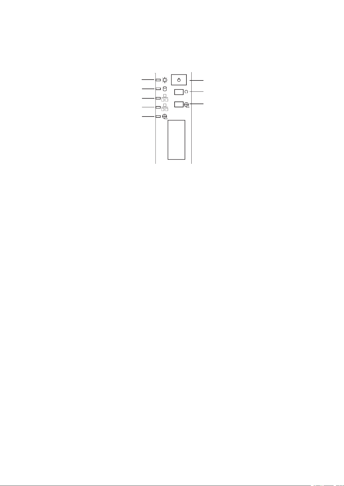
At the front of the case, you can find the neccessary controls like power button, reset button and the
HDD LEDs. Press the power button one time briefly in order to boot the server.
Figure 1. PLATINUM 200 I Controls
A. Power LED E. Fan Warning LED
HDD LED F. Power switch
B.
C. NIC2 LED G. Reset switch
NIC1 LED H. Disable Fan Warning
D.

8
2 Board Features
This chapter briefly describes the main features of the mainboard.
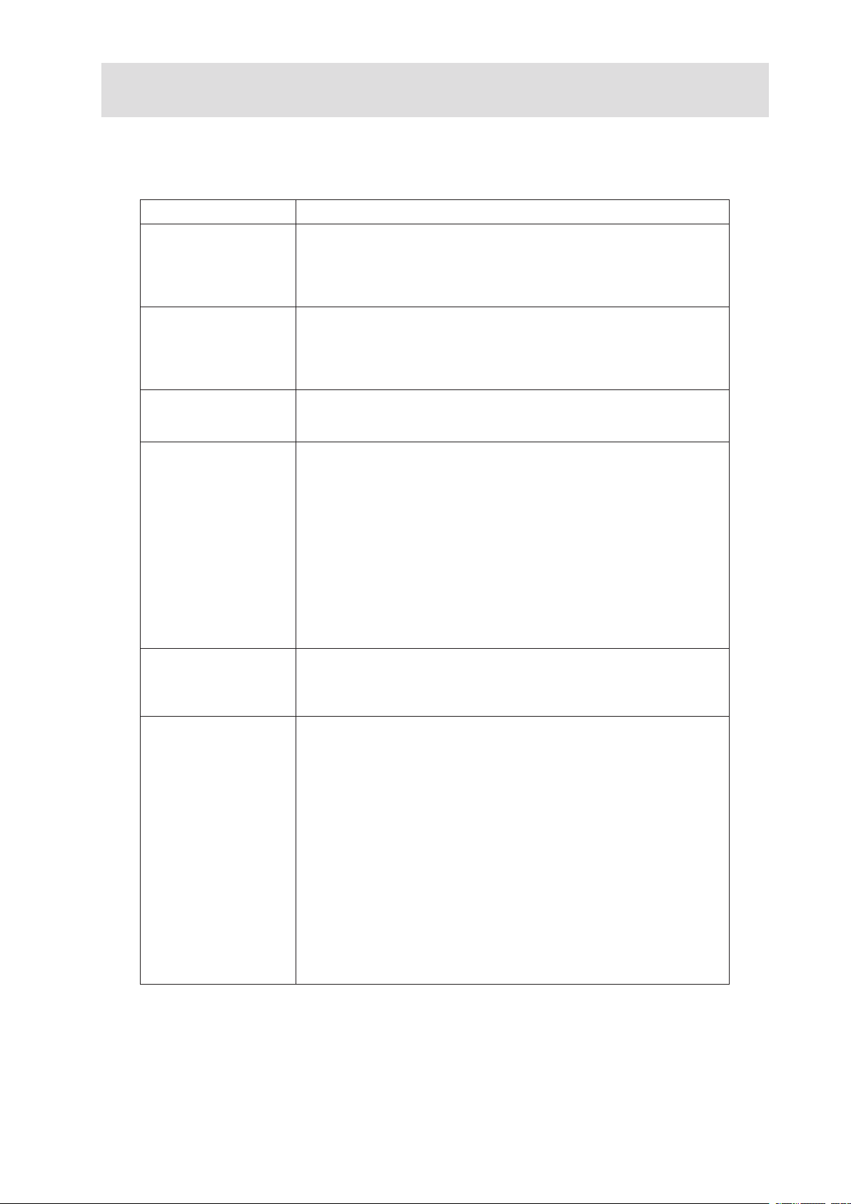
Table 1 summarizes the major features of the board.
Table 1. Feature Summary
Feature Description
Processor • Support for one Intel
processor in the LGA775 package
• Supports Intel
• Supports Intel® Hyper-Threading Technology
• Supports Intel® Extended Memory System 64 Technology (EM64T)
Memory • 4 DIMM sockets supporting 400/533/667 MHz DDR2 DIMMs
• Data bandwidth per channel of 4.2 GB/s or 8.4 GB/s in dual channel
when using DDR2 667 MHz
• Support for up to two DDR2 channels for a total of 4 DIMMs (2
DIMMs / Channel) providing up to 8 GB max memory capacity
Intel® E7230 Chipset
Components
I/O Control Super I/O: SMsC* LP47M182NR
Video Integrated stand-alone ATI ES1000 graphics engine that supports
Board I/O Subsystem Five independent PCI Buses:
• Intel® E7230 MCH Memory Controller Hub
• Intel® ICH7R I/O controller
• 12-deep In-Order Queue
External connections:
• Stacked PS2 Keyboard/Mouse connections
• RJ45 Serial B port
• Two RJ45 NIC connectors for 10/100/1000 Mbps connections
• Two USB 2.0 ports
Internal connections:
• One USB port header which supports two USB 2.0 ports
• One DH10 Serial A header
• Two SATA-150 connectors with integrated RAID 0/1 support
• One ATA-100 connector
• SSI-compliant 34-pin control panel header
standard SVGA drivers with analog display capabilities. The graphics
subsystem has 16 MB of dedicated memory to support the onboard
video controller
• Segment A - Two PCI 32-bit/33-MHz 3.3 V Universal connectors
supporting full length PCI add-in cards (Adapters which support
5 V only are not supported) and one embedded Intel® 10/100/ 1000
82541PI gigabit Ethernet Controller (Supports PCI Specification, Rev
2.3)
• Segment B - One x1 PCI Express resource implemented as a single
x4 PCI Express connector supporting x1/x2/x4 PCI Express add-in
cards
• Segment C - One x1 PCI Express resource implemented as an
embedded Intel® 10/100/1000 82573E gigabit Ethernet Controller
• Segment D - One x4 PCI Express resource implemented as a single
x8 PCI Express connector supporting x1/x2/x4/x8 PCI Express add-in
cards
• Segment E - One x8 PCI Express resource implemented as a single
x8 PCI Express connector supporting x1/x2/x4/x8 PCI Express add-in
cards
®
Pentium® D, Pentium® 4 or Celeron® D
®
Dual Core Architecture
 Loading...