


Service Manual
Model: Belinea 101920
Art. No. 111912
MAXDATA Systeme GmbH
Elbestr. 12-16
45768 Marl / Germany

Table of Contents
CONTENTS PAGE
Sections
1. Safety Precaution 1
2. General Information 1
3. Supported Modes 2
4. Video Input Signal 3
5. Video Input Terminal 4
6. Theory of Operation 6
7. OSD Menu Function 7
8. Specification 8
9. Critical Parts Specification 9
10. Block Diagram 22
11. Parts List 23
12. Schematic Diagram 30
13. Wave Form _____________________________________________ 34
14. LIPS-Schematic Diagram _________________________________ 39
15. PCB Layout ____________________________________________ 43

--1--
Belinea Technical Service Manual
Safety Precaution
WARNING
Service should not be attempted by anyone unfamiliar with the necessary precautions on this
monitor.
The followings are the necessary precautions to be observed before servicing.
1. When managing this monitor, cover with shield plate to avoid to scrach on LCD surface.
2. When replacing a chassis in the cabinet, always be certain that all the protective devices are
put back in place, such as nonmetallic control knobs, insulating covers, shields, isolation
resistor capacitor network etc.
3. Before returning the monitor to the customer, always perform an AC leakage current check
on the exposed metallic parts of the cabinet, such as signal connectors, terminals, screw
heads, metal overlays, control shafts etc, to be sure the monitor is safe to operate without
danger of electrical shock.
General Information
1. General Description
This 19"LCD color display monitor is operated in R,G,B drive mode input.
2.Operating instructions
2-1.Front
Power Switch, Menu, Select, Down, Up, DPMS (Power) LED
2-2.Rear
Input connector (AC &Signal Cable &DVI Cable &Audio Cable)
2-3.OSD Controls
Brightness, Contrast, Color Control, Position (H.V), Clock Phase, Miscellaneous (Recall,
OSD Time, OSD Position, Auto Color), Language, Audio, Auto Adjust, Input Select
3.Electrical Characteristic
3-1.Power Supply
AC/DC-Input Voltage :100V~240V
Input Current :1.5A (Max)
Input Ferquency :47~63Hz
-Output Voltage 12V /2.2A,5V/1.8A
3-2.Video Input Signal
Level :0~770mV max analog signal (at 75 ohm termination to ground)
Polarity :Positive or Negative
3-3.Horizontal Synchronization Signal
Level :TTL High :1.6~5.0V
Low :0.0 ~ 1.2V
Polarity :-or +
Frequency :31kHz ~80kHz analog, 31kHz~64kHz digital
3-4.Vertical Synchronization Signal
Level :TTL High :1.6~5.0V
Low :0.0 ~ 1.2V
Polarity :-or +
Frequency :56Hz ~75Hz analog, 60Hz digital
--2--
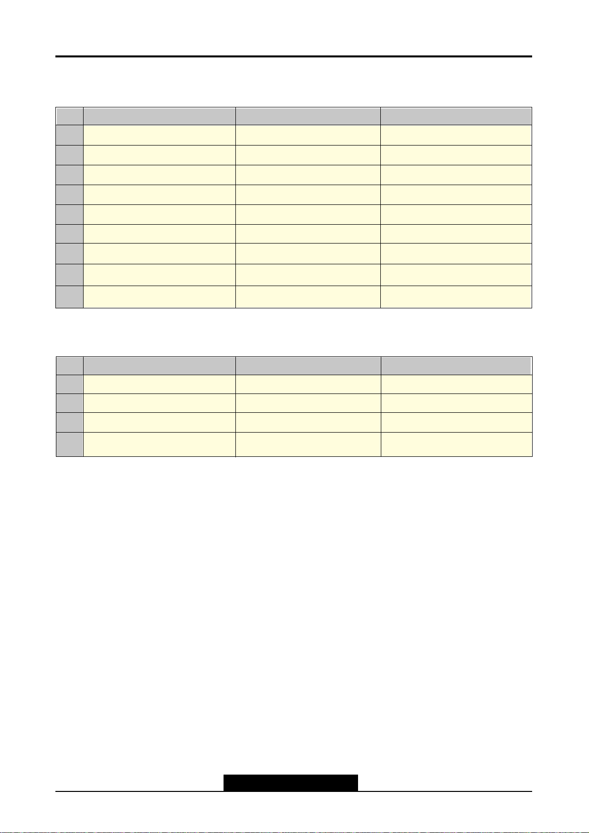
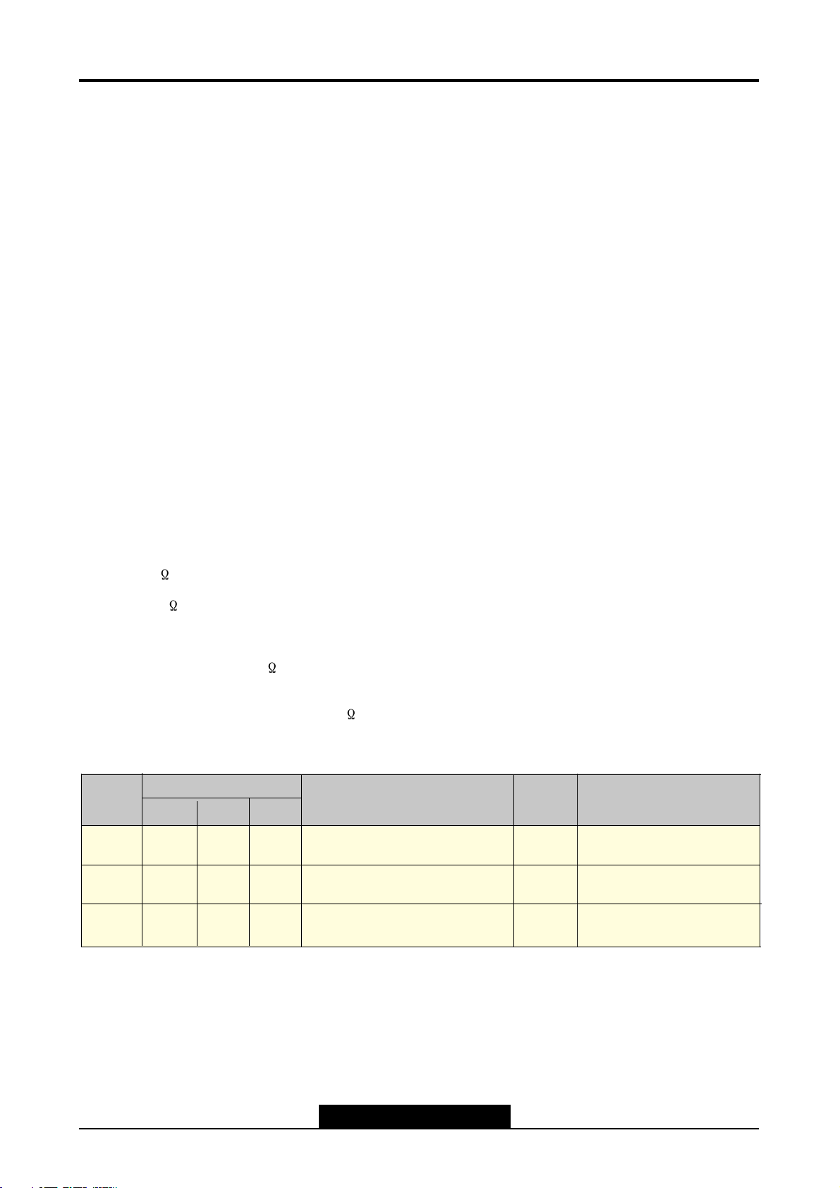
Support Modes
*Analog R,G,B Input
*Digital R,G,B Input
NO
1
2
3
4
Resolution
640 x 480
800 x 600
1024 x 768
1280 x 1024
H Frequency(KHz)
31.5
37.9
48.4
63.9
V Frequency(KHz)
59.9
60.3
60.0
60.0
NO
1
2
3
4
5
6
7
8
9
Resolution
720 x 400
640 x 480
640 x 480
800 x 600
1024 x 768
1024 x 768
1024 x 768
1280 x 1024
1280 x 1024
H Frequency(KHz)
31.5
31.5
37.5
37.9
48.4
56.5
60.0
63.9
79.9
V Frequency(KHz)
70.1
59.9
75.0
60.3
60.0
70.1
75.0
60.0
75.0
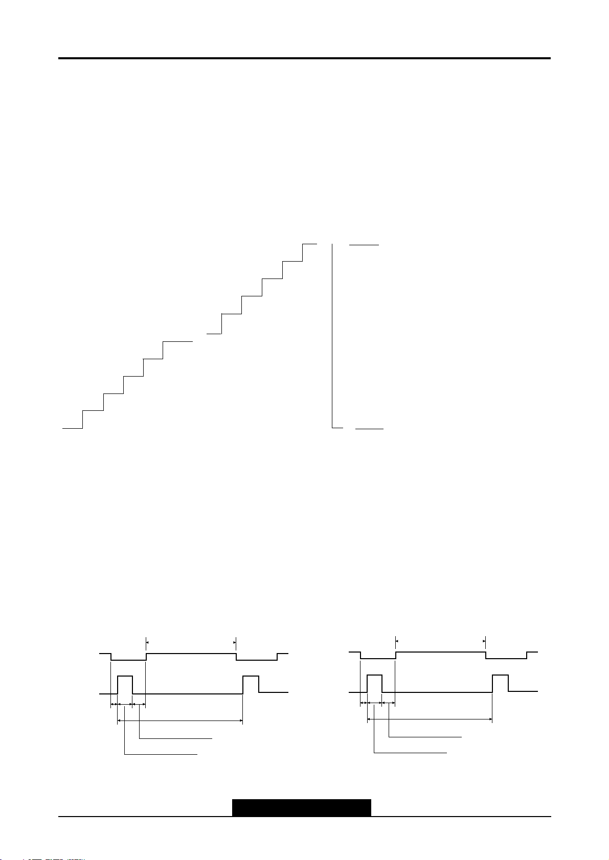
Video Input Signal
Recommended signal are shown below
•Video Signal
Video level : 0 to 770mV
Polarity : positive or Negative
Video Input : RGB separated
Analog level
Sync input : H-Sync(TTL level)
V-Sync (TTL level)
•Waveform
Video input(R.G.B)
--3--
Belinea Technical Service Manual
0
1
2
3
4
251
252
253
254
255
700mV
0mV
• Signal: 256 level gray
scale
• Linear stepping:
(2.73mV ~ 256 Steps)
ACTIVE (T4)
Front Porch
(T5)
Period (T1)
Sync Width (T2)
Back Porch (T3)
ACTIVE (T4)
Front Porch
(T5)
Period (T1)
Sync Width (T2)
Back Porch (T3)
• H-Sync
• V-Sync
--4--
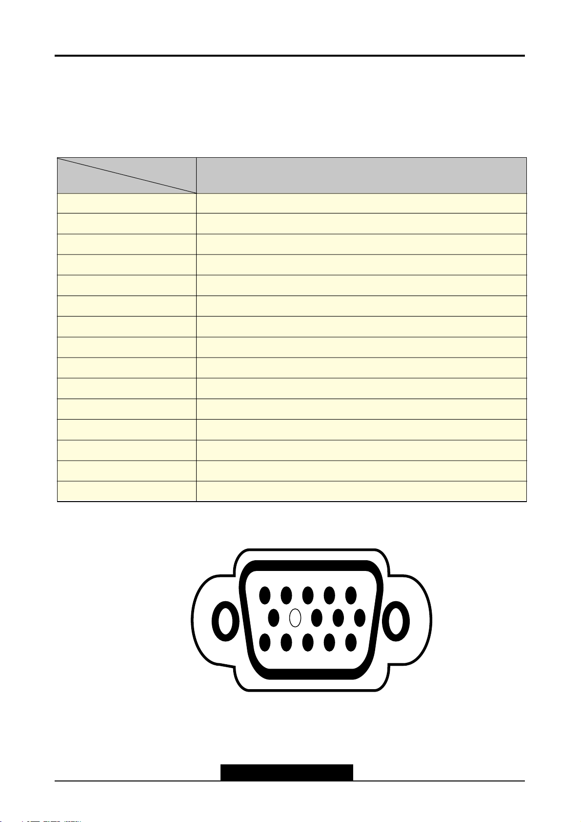
Video Input Terminal
1. Analog
A 15 Pin D-sub connector is used as the input signal connector
Pin and input signals are shown in the table below.
Pin Description
D-Sub miniature connector
1
2
3
45
10
9 8
7
6
11
12
13
14
15
SIGNAL
PIN NO.
3
2
1
5
4
6
7
8
9
10
11
12
13
14
SEPARATE SYNC/
DDC 1/2B
RED
GREEN
BLUE
GND
GROUND or Cable Detect
RED GROUND
GREEN GROUND
BLUE GROUND
N.C
GROUND or Cable Detect
GROUND
DDC Data
H-SYNC
V-SYNC
15
DDC Clock
--5--
Belinea Technical Service Manual
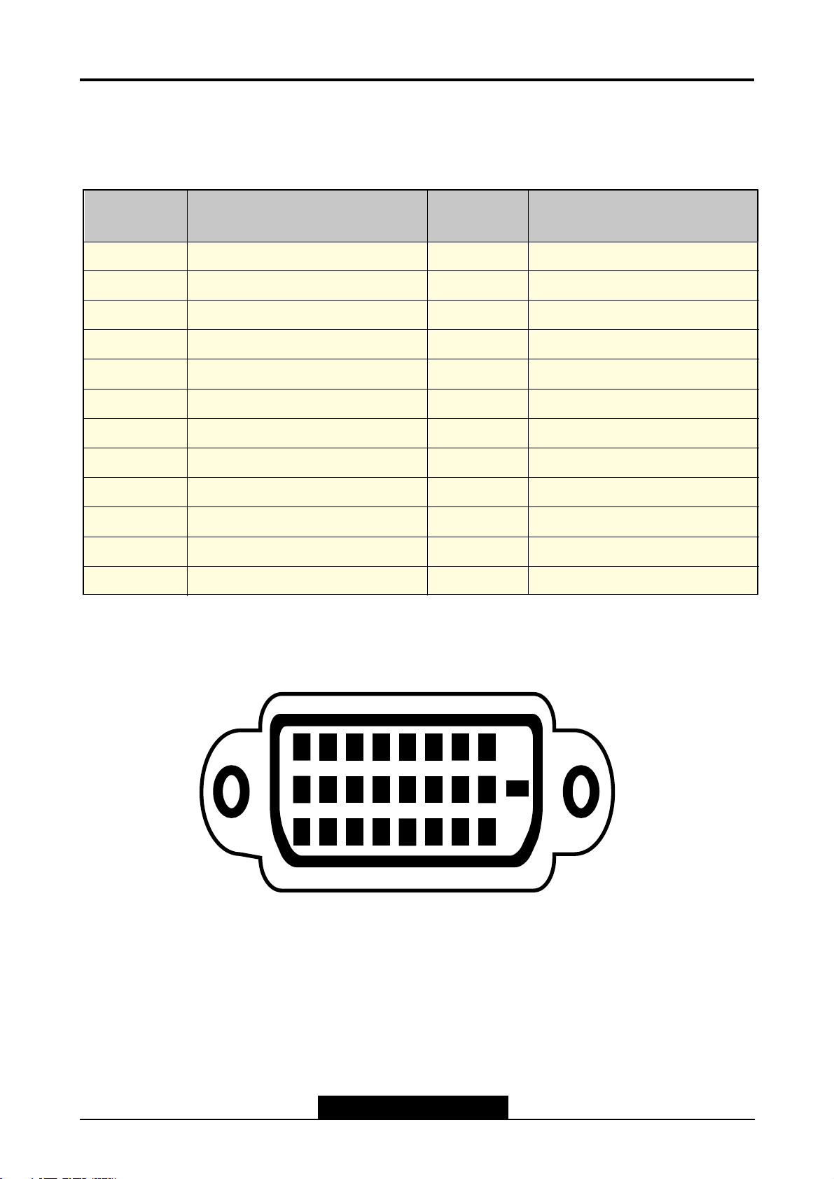
Pin Description
2. Digital
24 Pin DVI-D Interface connector is used as the input signal connector Pin
and input signal are shown in the table below.
Digital-Only Receptacle Connector
8
7
6
5
43
1
2
10
9
17
18
19
20 21 22 23 24
16
1514
13
12
11
PIN NO.
3
2
1
5
4
6
7
8
9
10
11
12
SEPARATE SYNC/
DDC 1/2B
T.MD.S Data 2-
T.MD.S Data 2+
T.MD.S Data2/ Shield
N.C
N.C
DDC Clock
DDC Data
No Connect
T.MD.S Data1-
T.MD.S Data1+
T.MD.S Data 1/3 Shield
N.C
PIN NO.
15
14
13
17
16
18
19
20
21
22
23
24
N.C
+5V Power
Ground(for +5V)
Hot Plug Detect
T.M.D.S Data 0-
T.M.D.S Data 0+
T.M.D.S Data 0/ Shield
N.C
N.C
T.M.S.D Clock Shield
T.M.D.S Clock +
T.M.D.S Clock -
SEPARATE SYNC/
DDC 1/2B
--6--
Theory of Operation
1. DC/AC INVERTER
Input voltage : DC 12V
Input current : 2.2A (Max)
Output current : 7.0mArms (TYP)
Frequency(switching) : 60KHz (Max)
Output Power : 17W (Typ.)
On/off control voltage : 5.0V
2. AC/DC ADATOR
This display device shall maintain the specified per formances in the range described
below:
Frequency : 50/60Hz
Voltage : 100 - 240Vac RMS
The following consumption requirments shall be met:
Power Consumption : 45W (max absolut value)
Current consumption : < 1.0 Aac RMS
Output Specification:
Output1 : 12V/2.2A
Output2 : 5V/1.8A
3, Audio System
This monitor has a audio system including two micro loudspeakers.
Each of two micro loudspeakers has a 2W (Max) output power.
This system also supports a headphone (earphone) output.
- Auto Signal Input : < 600mVp-p(Max)
- Auto Amplifiers
2W+2W Amplifier with DC Volume Control (for two miro loudspeakers)
RL=8 @THD=10% Vcc=14V (min, 10V, max. 15V)
- Dual-Audio Power Amplifier (for a headphone outpur)
RL=32 @THD=10% Vcc=4.5V (min, 1.8V, max. 15V)
-Speaker
Micro Loudspeaker spec.
Normal impedance 8 +/- 15% at 1.0V 1.5KHz
Resonance Freq . 550Hz +/- 110Hz at 1.0V
Freq. Range 550Hz ~ 20KHz
Power Handling Capa. 1.0W / 8 (2.83V)
4. DPMS MODE
Status
on
Pulse
Pulse
Active
Blank
No
Pulse
No
Pulse
off
mode
Signal
Power
Consumption
-
Within
5 Sec
Recovery
Time
Orange
LED
Indicator
Green
45W With Audio
Less Than 1W
H-Sync
V-Sync Video
Blank
No
Pulse
No
Pulse
off
switch
Within
5 Se
Dark
Less Than 1W
--7--
Belinea Technical Service Manual
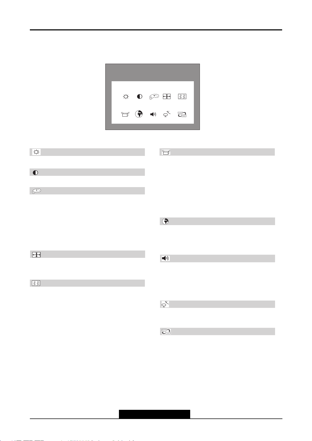
OSD MENU FUNCTIONS
1280 x 1024
H : 64.0 V : 60.0
BRIGHTNESS
ETC
Brightness
Controls the picture brightness.
Contrast
Controls the picture contrast.
Color Control
Color Control:
Three different color temperatures are available:
User, Bluish and Reddish. Select the desired setting
by pressing the /VOLUME or /MUTE buttons.
User:
You can also defi ne the RGB values yourself. Press the
/VOLUME or /MUTE buttons to select Red, Green
or Blue. Then press the SELECT/AUTO button.
Position
H Position: Controls the picture’s horizontal position.
V Position: Controls the picture’s vertical position.
Clock Phase
Phase: Adjusts the internal clock’s time lag in order to
optimize the screen image.
Clock: Sets up the internal clock. Larger values make
the displayed image appear wider; smaller values make
it appear compressed.
ETC
Miscellaneous
Recall: Restores the image settings to their fac to ry
va lues.
OSD Time: Determines the time (in se con ds) to wait
before the OSD menu is au to ma ti cal ly closed when no
changes are made.
OSD Position: Controls the horizontal and ver ti cal
po si ti on of the OSD menu.
Auto Color: Automatic color settings.
Language
Language: OSD menu language selection: English,
German, French, Italian, Spanish, Portuguese, Danish,
Swedish, Finnish, Dutch, Korean, Japanese, Chinese.
Audio
Volume: Adjusts the monitor loudspeaker output
vo lu me. Select the desi red vo lu me by pres sing the
/VOLUME or /MUTE but tons.
Audio On/Off: You can mute sound output or switch
the sound back on.
Auto Adjust
Automatically selects the optimal values for the image
settings (image position, phase, etc.).
Input Select
Controls the selection of the input signal. The monitor
allows you to make the following connections: analog
graphics card via the 15-pin mini D-Sub interface (see
fi g. 2a), digital graphics card via the DVI-D interface
(see fi g. 2b).
--8--
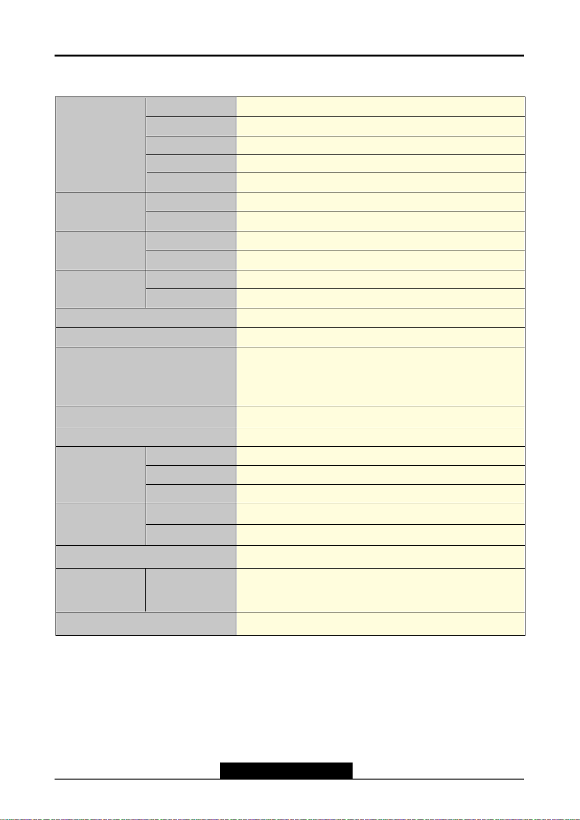
Specification
LCD Module
SIZE
19” Viewable diagonal
Pixel Pitch 0.294 mm
Contrast Ratio
Response Time
600 : 1(TYP)
Brightness
250 cd/m2(TYP)
25ms (TYP.)
Input
Signal
R.G.B Analog, Digital TMDS
Connector
15 pin D-SUB Connector/Digital 24Pin DVI
SYNC
H-Freq
31.0 kHz~80 kHz
V-Freq
56Hz ~75 Hz
Display
Area
Color
376.32 X301.056(V)mm
16.7M
Recommand Resolution
Video Bandwidth
User Control
&
OSD Control
BRIGHTNESS, CONTRAST, COLOR CONTROL,
MISCELLANEOUS, AUTO ADJUST, RECALL, LANGUAGE,
H.V-POSITION, CLOCK-PHASE, INPUT SELECT
Power Management
VESA DPMS Standard
Plug & Play
VESA DDC 1/2B
Safety &
Regulation
EMC
Ergomomi
Safety
FCC CLASS B , CE , VCCI
TCO03
cULus, CE, TUV-GS, SEMKO, FIMKO
Temperature
5 to 90%(Non-condensing)
packed
Operating
Storage
0 to 35 °C
- 5 to 45 °C
Weight
unpacked
VESA FPMPMI
Dimension(LxHxD mm)
7.9Kg
415 X 443 X 201mm
5.6Kg
1280X1024 @ 60Hz
135Mhz

--9--
Belinea Technical Service Manual
Critcal Parts Specification
1. LCD Module
LTM190EU-L03is a color active matrix TFT (Thin Film Transistor) liquid crystal
display(LCD)that uses amorphous silicon TFTs as switching devices.This model is
composed of a TFT LCD panel, a driver circuit and a back-light system. The resoution of
a 19.0” contains 1280x1024 pixels and can display up to 16.7 million colors with wide
viewing angle of 89°or higher in all directions. (Vertical viewing angle : 178
°
, Horizontal
viewing angle : 178
°
)
Display area
Drive system
Display color
Number of Pixel
Pixel arrangement
Pixel pitch
Weight
Contrast ratio
Viewing angle
Horizontal
Vertical
Response time
Luminance
Signal voltage
Supply Voltage
Backlight
LCD Type
376.32(H)X301.056(V)mm
A-Si TFT
16.7M Colors
1280x1024
RGB vertical strip
0.294(H)X0.294(V)mm
2.75kg
600:1
89 degree, 89 degree
89 degree, 89 degree
25ms (max)
250cd/m2 (typ)
Digital RGB signals, Sync signals (H, V-Sync),
5.0V
Edge light type : Four colt catdode fluorescent lamps
With in-verter
LTM190E1-L03
--10--
MC68HC705BD7B
MST7131A
, and DE), and input
character font
MHz dot clock for
FEATURES
Ÿ High-quality zoom and shrink scaling engine
(Compatible with VGA thru SXGA)
Ÿ Integrated 8-bit triple-ADC/PLL
Ÿ On-screen display controller (OSD)
Ÿ Supports single-RGB inputs
Ÿ Integrated DVI receiver
Ÿ Supports composite sync and SOG separator
Ÿ Programmable 10-bit gamma correction
Ÿ Integrated Brightness & Contrast control
adjustment
Ÿ Supports PWM backlight intensity control
Ÿ Supports sRGB
Ÿ Green PC and low EMI features
Ÿ Built-in LVDS transmitter
Ÿ Low standby power mode (< 16mA)
n High-Performance Scaling Engine
Ÿ Programmable shrink/zoom capabilities
Ÿ High-quality scaling for all VESA and IBM mode
to fit screen
Ÿ Variable sharpness control
n Analog RGB Compliant Input Port
Ÿ Supports up to SXGA at 75Hz
Ÿ Supports Composite Sync and SOG
(Sync-on-Green) separator
n Integrated DVI Receiver
Ÿ Operates up to 135 MHz
Ÿ Single link on-chip DVI receiver
Ÿ Direct connect to all DVI compliant
transmitters
n Auto-Detection/Tune
Ÿ Auto input signal format (SOG, Composite,
Separated HSYNC, VSYNC
mode (all VESA & IBM modes w/ resolution
and polarity) detection
Ÿ Auto-tuning function including phasing,
positioning, offset, gain, and jitter detection
Ÿ Smart screen-fitting
n On-Screen OSD Controller
Ÿ Built-in OSD generator with 256
programmable RAM
Ÿ Supports for 4/8 multi-color fonts
Ÿ Gradient color function
Ÿ Supports button function
Ÿ Pattern generator for production test
Ÿ Supports OSD MUX and alpha blending
capability
n LVDS Display Interface
Ÿ Supports Dual Link up to 135
SXGA
Ÿ Supports 2 data output formats: Thine & TI
data mappings
Ÿ Compatible with TIA/EIA
Ÿ With 6/8 bits options
Ÿ Supports reduced swing LVDS for low EMI
Ÿ Supports flexible spread spectrum frequency
with 360Hz~11.8MHz and up to 25%
modulation
n External Connection/Component
Ÿ Supports serial bus (up to 400Kbit/sec)
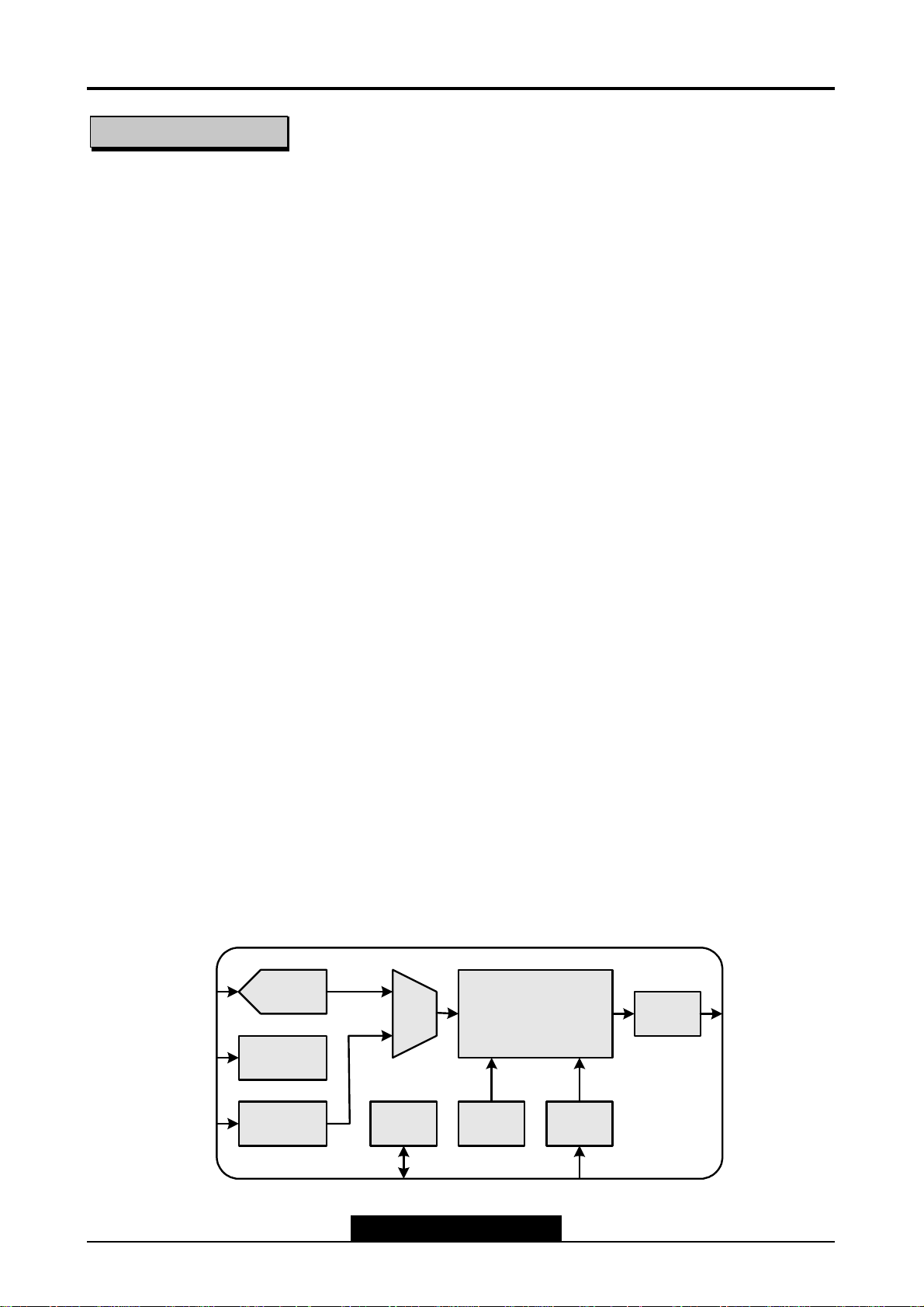
BLOCK DIAGRAM
Analog
RGB
Analog
HSYNC
DVI
ADC
ADC_PLL
DVI
interface
MUX
Scaling
Engine
OSD SSCHOST
MCUXTAL/EXT CLK
LVDS
To Panel
--11--
Belinea Technical Service Manual
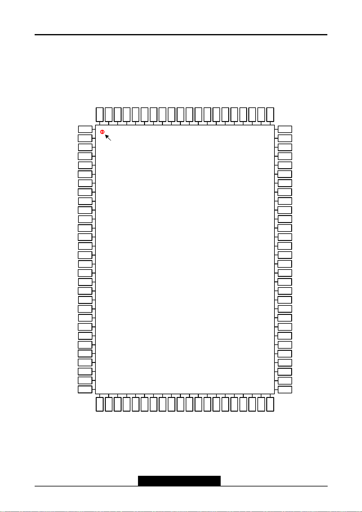
PIN DIAGRAM (MST7131A)
HWRESET
XIN
XOUT
AVDD_MPLL
AVSS_MPLL
HSYNC0
95
96
97
98
99
100
NC
89
90
91
92
93
94
NC
81
82
83
84
85
86
87
88
BYPASS
NC
NC
NC
NC
VDDC
GNDC
GNDP
VDDP
NC
NC
NC
VSYNC0
AVSS_DVI
R+
R-
AVSS_DVI
G+
G-
AVDD_DVI
B+
B-
AVSS_DVI
CK+
CK-
AVDD_DVI
REXT
AVDD_PLL
AVSS_PLL
AVDD
AVSS
BIN0M
BIN0P
GIN0M
GIN0P
SOGIN0
RIN0M
RIN0P
AVSS
AVDD
REFP
REFM
10
11
12
13
14
15
16
17
18
19
20
21
22
23
24
25
26
27
28
29
30
1
2
3
4
5
6
7
8
9
Pin 1
MST7131A
XXXXXXXXXXX
XXXXX
80
AVSS_MPLL
79
LVB0M
78
LVB0P
77
GNDP
76
VDDP
75
LVB1M
74
LVB1P
73
LVB2M
72
LVB2P
71
LVBCKM
70
LVBCKP
69
LVB3M
68
LVB3P
67
VDDC
66
GNDC
65
GNDP
64
VDDP
63
LVA0M
62
LVA0P
61
LVA1M
60
LVA1P
59
LVA2M
58
LVA2P
57
LVACKM
56
LVACKP
55
GNDP
54
VDDP
53
LVA3M
52
LVA3P
51
GNDP
31
32
33
34
35
36
37
38
39
40
41
42
43
44
45
46
47
48
49
50
CS
AVSS
INT
SCL
SDA
NC
NC
PWM0
PWM1
NC
NC
NC
VDDP
GNDP
VDDP
VDDC
GNDC
GNDP
VDDC
GNDC

--12--
MECHANICAL DIMENSIONS
Symbol
A - - 3.30 - - 0.130
A1 0.20 - - 0.008 - A2 2.72 2.85 2.98 0.107 0.112 0.117
D 22.95 23.20 23.45 0.903 0.913 0.923
D1 19.90 20.00 20.10 0.783 0.787 0.791
E 16.95 17.20 17.45 0.667 0.677 0.687
E1 13.90 14.00 14.10 0.547 0.551 0.555
Millimeter Inch
Min. Nom. Max. Min. Nom. Max.
Symbol
θ
b 0.26 - 0.36 0.010 - 0.014
c 0.14 0.15 0.16 0.006 0.006 0.006
e 0.50 0.65 0.80 0.020 0.026 0.032
L 0.73 0.88 1.03 0.029 0.035 0.041
L1 1.45 1.60 1.75 0.057 0.063 0.069
Millimeter Inch
Min. Nom. Max. Min. Nom. Max.
0° - 8° 0° - 8°
 Loading...