

Service Manual
Model : Belinea 101725
Art. No. 111707
MAXDATA Systeme GmbH
Elbestr. 12-16
45768 Marl / Germany
Contents
1. Precautions
Safety Precautions 4
Servicing Precautions
Electrostatically Sensitive Devices (ESD) Precautions
2. Product Specifications
Specifications 8
Dimensions
Pin Assignment Table D-Sub 15 Pin Connector
Timing Chart
3. Disassembly and Reassembly
4. Troubleshooting
6
7
9
10
10
11
No Power 14
No Video
No Picture
No Sound
5. Exploded View & Parts List
6. Packing & Unpacking
7. Electrical Parts List
Main Board 20
OSD Key Board
Others
15
16
16
17
19
22
22
2
Service Manual

Contents
8. Block Diagram
9. Wiring diagram
10. PCB Layout
Main PCB 28
Key PCB
Semiconductor Aead Identification
11. Schematic Diagram
CONTENTS
25
27
31
31
32
Copyright
2003 by Maxdata Systeme GmbH
All rights reserved.
This manual may not, in whole or in part, be copied,
photocopied, reproduced, translated, or converted to any
electronic or machine readable form without prior written
permission of Maxdata Systeme GmbH.
Belinea 101725 Service Manual
First edition April 2003
111707 Service Manual
3

Precautions
1. Precautions
Follow these safety, servicing and ESD precautions to prevent damage and to protect against
potential hazards such as electrical shock.
1-1 Safety Precautions
1-1-1 Warnings
1. For continued safety , do not attempt to modify the circuit board.
2. Disconnect the AC power Jack before servicing.
1-1-2 Servicing the LCD Monitor
1. When servicing the LCD Monitor Disconnect the AC line cord from the AC outlet.
2. It is essential that service technicians have an accurate voltage meter available at all times.
Check the calibration of this meter periodically .
1-1-3 Fire and Shock Hazard
Before returning the monitor to the user,perform the following safety checks :
1. Inspect each lead dress to make certain that the leads are not pinched or that hardware is not
lodged between the chassis and other metal parts in the monitor.
2. Inspect all protective devices such as nonmetallic control knobs, insulating materials, cabinet
backs, adjustment and compartment covers or shields, isolation resistor-capacitor networks,
mechanical insulators, etc.
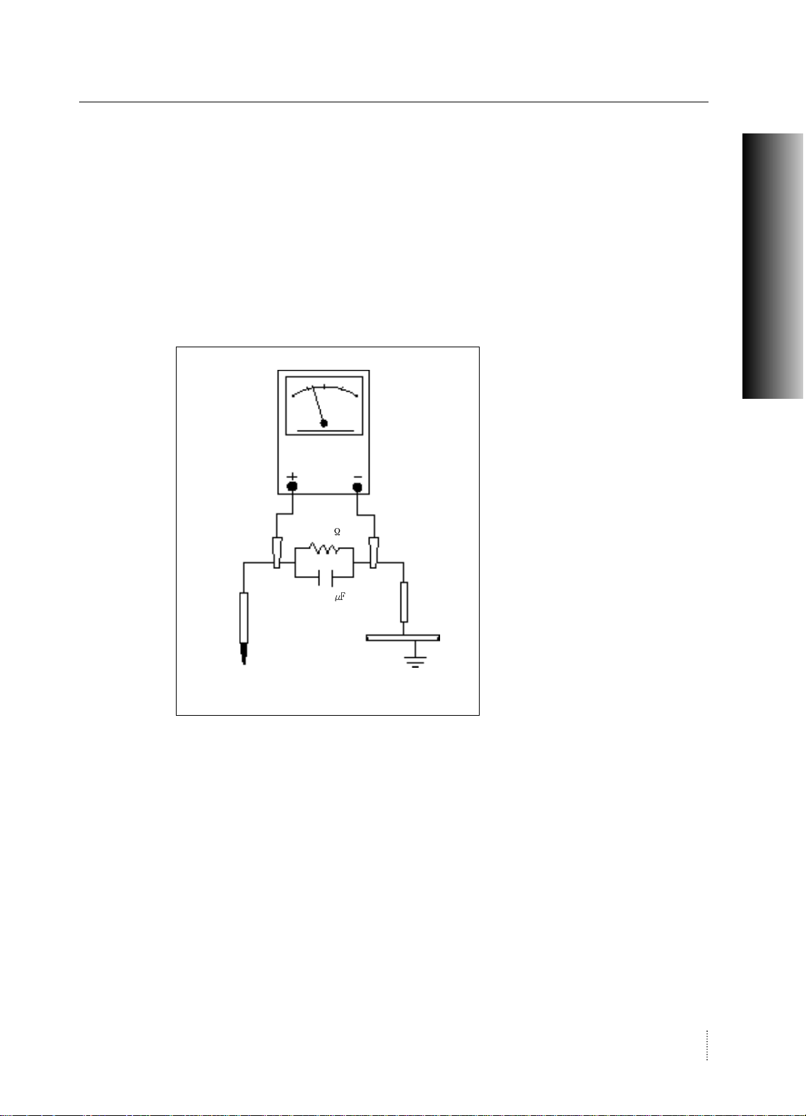
3. To be sure that no shock hazard exists, check for leakage current in the following manner.
Warning : Do not use an isolation transformer during this test.
a. Plug the AC line cord directly into a 120 Volt AC outlet.
b. Unisg two clip leads, connect 1.5
with an exposed metal cabinet part and a known earth ground, such as an electrical conduit or
electrical ground connected to an earth ground.
, 10 watt resistor paralleled by a 0.15
capacitor in series
111707 Service Manual
4
Precautions
c. Use a SSVM or VOM with 1000 ohms per-volt or higher sensitivity to measure the AC voltage
drop across the resistor (see Figure 1-1).
d. Connect the resistor to an exposed metal part having a return path to the chassis(metal cabinet,
screw heads, knobs, shafts, escutcheon, etc.) and measure the AC voltage drop across the
resistor.
e. Any reading of 5.25 Volt RMS ( this corresponds to 3.5 milliampere AC ) or more is excessive
and indicates a potential shock hazard. Correct the shock hazard before returning the monitor to
the user.
AC Voltmter
1500
Test Probe
PRECAUTION
0.15
To Exposed
Metal Parts
To Known
Earth Ground
Figure 1-1.
Leakage Current Test Circut
1-1-4 Product Safety Notices
Some electrical and mechanical parts have special safety-related characteristics which are often not
evident from visual inspection. The protection they give may not be obtained by replacement that
does not have the same safety characteristics as the recommended replacement part may create
shock, fire and /or other hazards. Product safety is under review continuously and new instructions
are issued whenever appropriate.
111707 Service Manual
5

Precautions
1-2 Servicing Precautions
WARNING : An electrolytic capacitor installed with the wrong polarity might explode.
Caution : Before servicing instruments covered by this service manual and its supplements,
read and follow the Safety Precautions section of this manual.
Note : If unforeseen circumstances create conflict between the following servicing preautions
and any of the safety precautions, always follow the safety precautions.
1-2-1. General Servicing Precautions
1. Servicing precautions are printed on the cabinet, and should be followed closely .
2. Always unplug the unit's AC power cord from the AC power source before attempting to :
(a) remove or reinstall any component or assembly , (b) disconnect PCB plugs or connectors,
(c) connect a test component in paralled with an electrolytic capacitor.
3. Some components are raised above the printed circuit board for safety. An insulation tube or tape
is sometimes used. The internal wiring is sometimes clamped to prevent contact with thermally hot
components. Reinstall all such elements to their original position.
4. After servicing, always check that the screws, components and wiring have been correctly
reinstalled. Make sure that the portion around the serviced part has not been damaged.
5. Check the insulation between the blades of the AC plug and accessible conductive parts
(examples; metal panels, input terminals and earphone jacks)
6. Insulation Checking Procedure : Disconnect the power cord from the AC source and turn the power
switch ON. Connect an insulation resistance meter(500V) to the blades of the AC plug.
The insulation resistance between each blade of the AC plug and accessible conductive parts
(see above) should be greater than 1 megohm.
7. Always connect a test instrument's ground lead to the instrument chassis ground before connecting
the positive lead; always remove the instrument's ground lead last.
111707 Service Manual
6

Precautions
1-3 Electrostatically Sensitive Devices(ESD) Precautions
Some semiconductor (solid state) devices can be easily damaged by static electricity . such
components are commonly called Electrostatically Sensitive Devices(ESD). Examples of typical ESD
devices are integrated circuits and some field-effect transistors. The following techniques will reduce
the incidence of component damage caused by static electricity .
1. Immediately before handling any semiconductor components or assemblies, drain the electrostatic
charge from your body by touching a known earth ground. Alternatively , wear a discharging
wrist strap device. To avoid a shock hazard, be sure to remove the wrist strap before applying
power to the monitor.
2. After removing an ESD-equipped assembly , place it on a conductive surface such as aluminum foil
to prevent accumulation of an electrostatic charge.
3. Do not use freon-propelled chemicals. These can generate electrical charges Sufficient to damage
ESDs.
4. Use only a ground-tip soldering iron to solder ESDs.
PRECAUTIONS
5. Use only an anti-static solder removal device. Some solder removal devices not classified as "anti-
static" can generate electrical charges sufficient to damage ESDs.
6. Do not remove a replacement ESD from its protective package until you are ready to install it. Most
relacement ESDs are packaged with leads that are electrically shorted together by conductive
foam, aluminum foid or other conductive materials.
7. Immediately before removing the protective material from the leads of a replacement ESD, touch
the protective material to the chassis or circuit assembly into which the device will be installed.
Caution : Be sure no power is applied to the chassis or circuit and observe all other safety
precautions.
8. Minimize body motions when handling unpackaged replacement ESDs. Motions such as brushing
clothes together, or lifting your font from a carpeted floor can generate enough static electricity to
damage an ESD.
111707 Service Manual
7
Precautions
2. Product Specifications
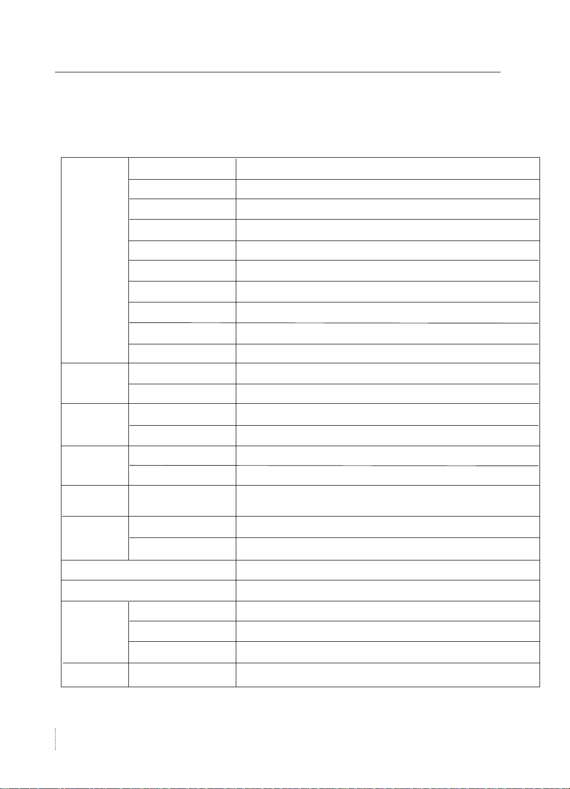
2-1 Specifications
LCD PANEL
Synchornization
Video Input
Power
Consumption
Model
Type
Screen Size
Maximum Resolution
Pixel Range
Display Colors
Contrast Rate
Viewing Angle
Response Speed
Brightness
Horizontal Frequency
Vertical Frequency
Video Signal
Synchronous Signal Mode
Maximum
Power Saving Mode
Belinea 101725
Amorphous Active Matrix Super TFT LCD
43.2cm ( Diagonal )
1280 X 1024 @ 75Hz
0.264mm X 0.264mm
16.2M
350 : 1
70° / 70° / 60°/ 60° ( left / right / up / down )
25ms
250 cd/m2
79.9KHz( Max )
75HZ( Max )
Analog RGB (0.714Vpp) 75 ohm
H,V separate TTL Sync,SOG,COMPOSITE
48W
Under 1W
Control Keys
Audio Output
Combo board
Wall Mount
Safety & EMI
Dimension
111707 Service Manual
8
Front part
Normal
Max
Safety Standard
EMI
Low Radiation
Size and Weight
MUTE,MENU,SELECT/AUTO,POWER,
- , + , VOL SWITCH
1W/Ch
1.5W/Ch
90~240Vac(50~60Hz),0.65A
VESA Standard
CB,TUV
CE
TCO' 99
380 X 176 X 368 / 5.8Kg
Product Specifications
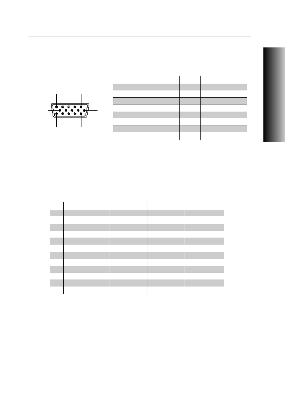
2-2 Pin Assignment
The 15-pin D-sub connector(male) of the signal cable(IBM systems)
Pin No Assignment Pin No Assignment
1
6
11
5
10
15
1 Red Video 9 5V Input
2 Green Video 10 Ground
3 Blue Video 11 Ground
4 N.C 12 SDA (DDC Data)
5 Ground 13 H-Sync
6 Red Video Ground 14 V-Sync
7 Green Video Ground 15 SCL (DDC Clock)
8 Blue Video Ground
2-3 Timing chart
This section of the service manual describes the timing that the computer industry recognizes as
standard for computer-generated video signals.
PRODUCT SPECIFICATIONS
No.
1
2
3
4
5
6
7
8
9
10
11
12
Display Mode
VGA (720 X 400)
VGA (640 X 480)
VGA (640 X 480)
SVGA (800 X 600)
SVGA (800 X 600)
XGA (1024 X 768)
XGA (1024 X 768)
SXGA (1280 X 1024)
SXGA (1280 X 1024)
MAC (640 X 480)
MAC (832 X 624)
MAC (1152 X 870)
Hor. Freq (kHz)
31.469
31.469
37.500
37.900
46.875
48.363
60.023
63.981
79.976
35.000
49.726
68.681
Ver. Freq (Hz)
70.087
59.940
75.000
60.320
75.000
60.004
75.029
60.020
75.025
66.667
74.551
75.062
Dot Clock (MHz)
28.322
25.175
31.500
40.000
49.500
65.000
78.750
108.000
135.000
30.240
57.284
100.000
111707 Service Manual
9
Product Specifications
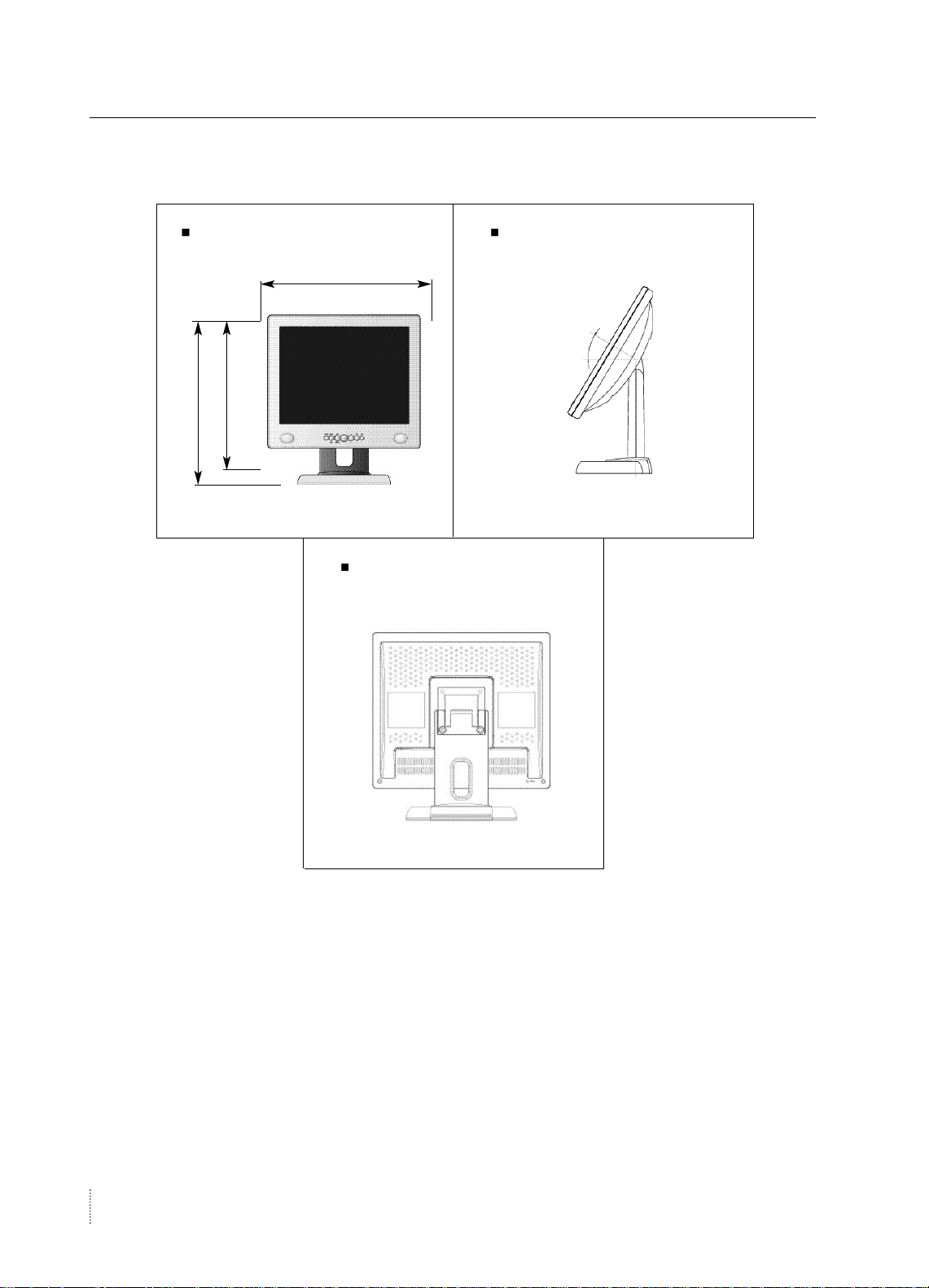
2-4 Dimensions
FRONT VIEW SIDE VIEW
176
368
380
REAR VIEW
10
Service Manual
 Loading...