

MAXDATA Belinea 101555 Service Manual

Service Manual
Model : Belinea 101555
Art. No. 111503
MAXDATA Systeme GmbH
Elbestr. 12-16
45768 Marl / Germany

___________________________________________________________________________________________
MAXDATA Belinea 101555
_________________________________________________________________
Content
Chapter
Page
A. WARNING
B. SAFETY PRECAUTIONS
1. DIMENSIONS
2. GENERAL INFORMATION
3. SPECIFICATIONS
4. THEORY OF OPERATION
5. DISASSEMBLY INSTRUCTIONS
6. CONTROL LOCATION
19
7. NECESSARY EQUIPMENT LIST
8. BLOCK DIAGRAM
9. CONDUCTOR VIEW
10. SCHEMATIC DIAGRAM
11. EXPLODED VIEW
12. TROUBLE SHOOTING HINTS
13. REPLACEMENT PARTS LIST
14. SPARE PARTS LIST
48
15. AUTO BALANCE
3
4
5
7
8
13
15
25
26
27
33
39
40
43
50

MAXDATA Belinea 101555
_____________________________________________________________________________________________________________________
WARNING
This service information is designed for experienced repair technicians only and is not
designed for use by the general public
It does not contain warnings or cautions to advise non-technical individuals of
potential dangers in attempting to service a product.
Products powered by electricity should be serviced or repaired only by experienced
professional technicians.
Any attempt to service or repair the product or products dealt within this service
information by anyone else could result in serious injury or death.
_____________________________________________________________________________________________________________________________
111503 Page 3
Confidential -
MAXDATA Belinea 101555
_____________________________________________________________________________________________________________________
SAFETY PRECAUTIONS
1. CAUTION:
No modification of any circuit should be attempted. Service work should only be performed after you
are through familiar with all of the following safety checks and servicing guide lines.
2. SAFETY CHECK
Care should be taken while servicing this LCD display. Because of the high voltage used in the inverter circuit.
These voltage are exposed in such areas as the associated transformer circuits.
3. POWER SUPPLY REQUIREMENTS
The internal power converter for this display utilizes a AC cord, the AC cord is detachable.
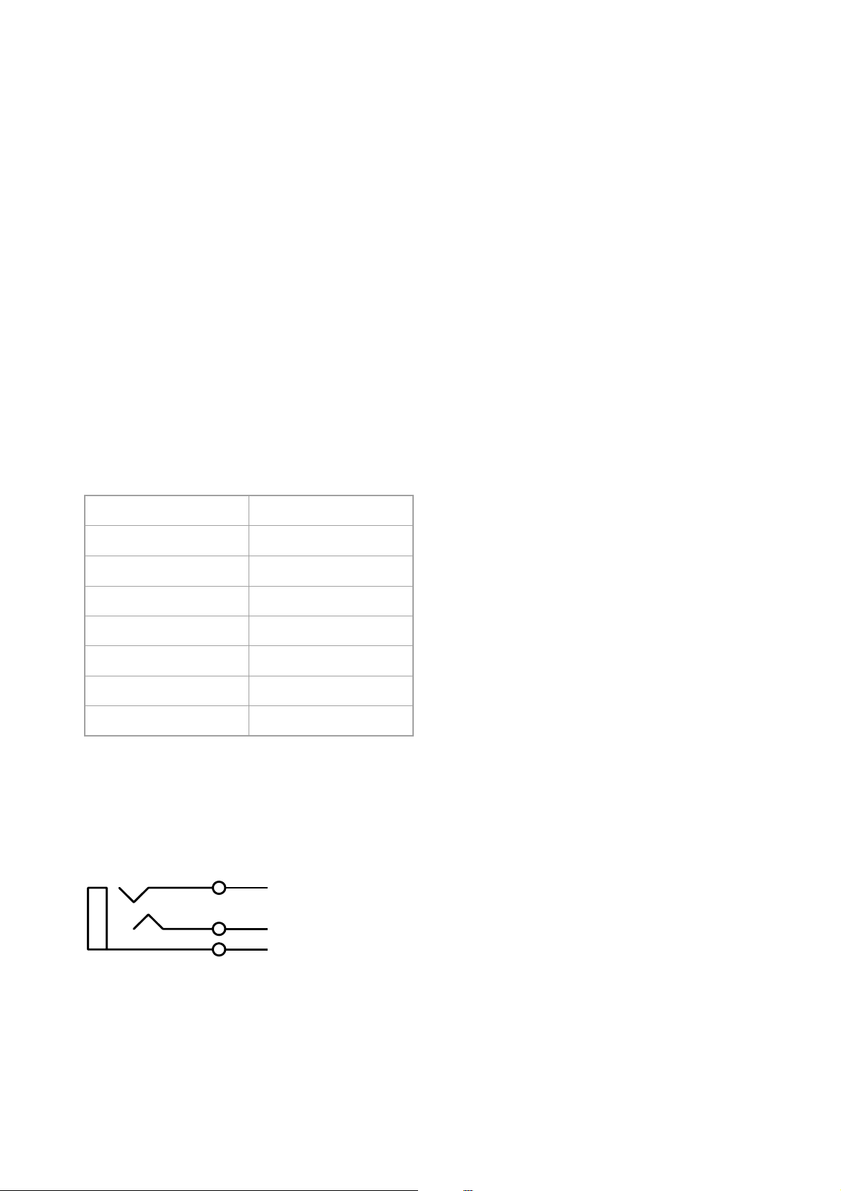
4. LEAKAGE CURRENT HOT CHECK
4-1 Plug the AC cord directly into the AC outlet. Do not use an isolation transformer during this check.
4-2 Connect a 1500 ohm, 10 watt resistor, paralleled by a 0.15uF capacitor between each
metallic part and a good earth ground.
4-3 Use an AC voltmeter with 1000 ohm / volt or more sensitivity and measure the AC voltage
across the combination 1500 ohm resistor and 0.15uF capacitor.
4-4 Move the resistor connection to each exposed metallic part and measure the voltage.
4-5 Reverse the polarity of the AC plug in the AC outlet and repeat the above measurement.
4-6 Voltage measured must not exceed 1.5 volt RMS, from any exposed metallic part to the ground.
A leakage current tester may be used in the above hot check, in which case any circuit measured
must not exceed 1 milliamp. In the case of a measurement exceeding the 1 milliamp value,
a rework is required to eliminate the chance of a shock hazard.
To Metal Parts
AC VOLTMETER
V
0.15u
.
1500 10W
Earth Ground
_____________________________________________________________________________________________________________________________
111503 Page 4
Confidential -
MAXDATA Belinea 101555
_____________________________________________________________________________________________________________________
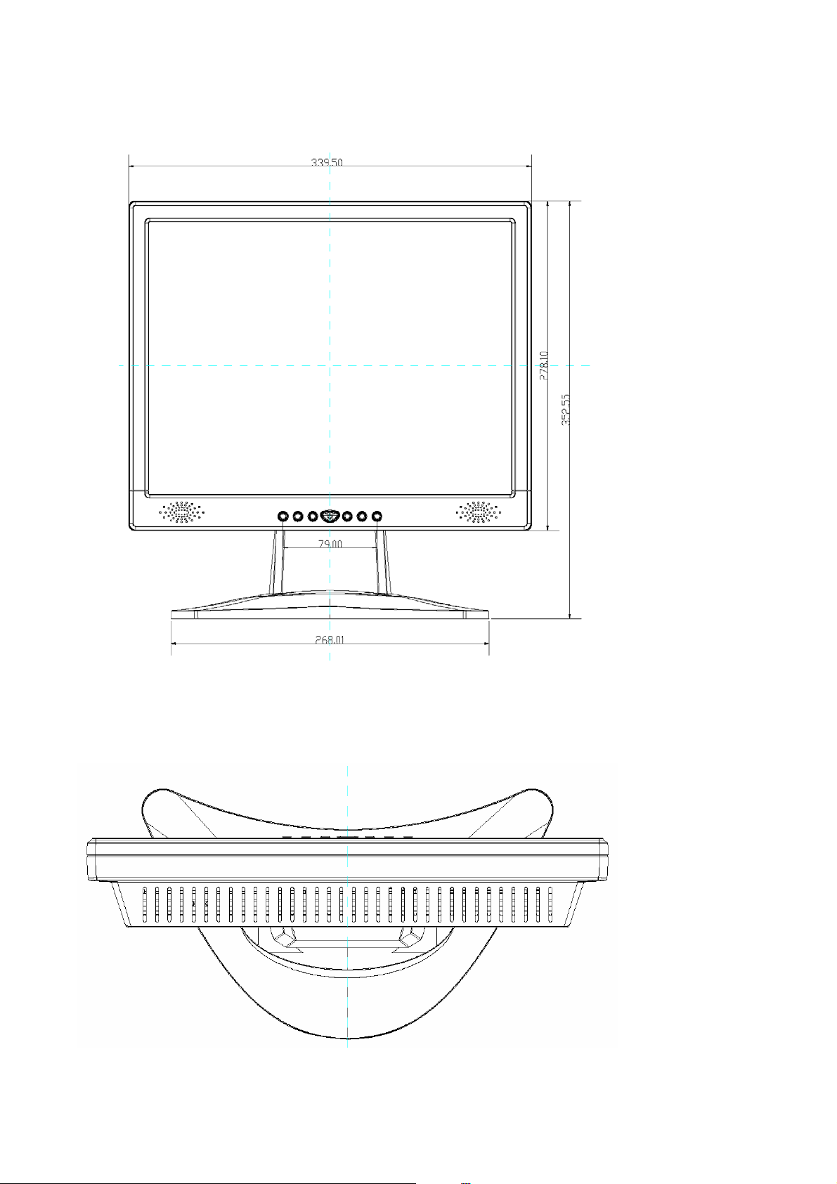
1. DIMENSIONS (Unit:mm)
1.1 Front View(ID1)
1.2 Top View
_____________________________________________________________________________________________________________________________
111503 Page 5
Confidential -

MAXDATA Belinea 101555
_____________________________________________________________________________________________________________________
1.3 Rear View
1.4 Side View
_____________________________________________________________________________________________________________________________
111503 Page 6
Confidential -

MAXDATA Belinea 101555
_____________________________________________________________________________________________________________________
2. GENERAL INFORMATION
2.1. OUTLINE
This monitor is a 15" multi-scan color LCD display with the following features.
OSD ( on screen display ) control allows easy user adjustment.
Power saving function, which helps saving energy, is also one of the highlights of this model.
2.2. FEATURES
2.2.1 Power Saving
The Built in Power Save function based on VESA-DMPS standard. Power energy shall be saved
by controlling the circuit in accordance with power save signal from computer.
2.2.2 OSD (on screen display) function
OSD ( 5 Languages ) function is excellent and new man-machine interface.
Anyone is able to set up the picture as he like through OSD menu.
2.2.3 Self Test function
Self Testing picture comes out by pushing any key in the case of no-connection with computer
or power saving operation. This function shows if monitor is alive or not and can be used for self
aging test.
2.2.4 Ergonomic design
Low emission design to meet TCO 99.
2.2.5 Multi scan with digital technology
8 bit micro controller controls the circuit operation to meet with wide range signal of
Fh = 31~61 kHz and Fv = 56~75 Hz. So VGA640x400, VGA640x480, SVGA800x600, XGA 1024x768 are
possible.
2.2.6 Factory preset
The product has 21 memory modes in total. 12 modes are preset and 9 modes are user definable.
2.2.7 Fine dot pitch
LCD panel with a fine dot pitch ( Horizontal: 0.297 mm / Vertical: 0.297 mm)
2.2.8 Superior display performance
High contrast : 350:1 ( Typical )
High brightness : 250 cd / m² ( Typical )
Wide view angle : 130 / 110 degrees ( H/V Typical )
2.2.9 Special function
VESA DDC2B ( Display Data Channel ) Compatible
_____________________________________________________________________________________________________________________________
111503 Page 7
Confidential -
MAXDATA Belinea 101555
_____________________________________________________________________________________________________________________
3. SPECIFICATION
3.1. Outline
3.1.1 Front Indication: POWER SW, LED (Green/Amber), UP, DOWN, LEFT, RIGHT, Set/Auto and MENU
key are located on the front panel.
3.1.2 Video signal cable connector, audio line-in receptacle and AC inlet are located on the back side cabinet.
3.1.3 OSD menu includes the following function. CONTRAST, BRIGHTNESS, H.POSITION, V.POSITION
COLOR-TEMPERATURE, CLOCK, PHASE, LANGUAGE, VOLUME, RECALL
3.1.4 CONTRAST and BRIGHTNESS can be directly controlled with UP / DOWN key.
3.1.5 VOLUME can be controlled with LEFT / RIGHT key.
3.2. MECHANICAL SPECIFICATIONS
3.2.1 Dimension Height : 340 mm
Width : 352 mm
Depth : 163 mm
3.2.2 Net Weight : 2.6 kg
3.2.3 Maximum Viewable Area: Diagonal 381mm (15")
3.3. PANEL SPECIFICATIONS
Part No.
3.4. CONNECTORS
3.4.1 AC inlet : CEE22 typed connector
3.4.2 Audio : Line-in receptacle
J1
PHONEJACK STEREO
_____________________________________________________________________________________________________________________________
HSD150SX84-C
6 bit Driver bit of panel
350:1 Contrast ratio
250 cd / m² Brightness
0.297 mm Pixel pitch
Typical 35 ms Response time
65/65/55/55 degreesView angle (L/R/T/B)
x=0.310,y=0.330Color coordinate white
1
2
3
111503
Page 8
Confidential -

MAXDATA Belinea 101555
g
y
)
y
N
g
d
(
)
_____________________________________________________________________________________________________________________
3.4.3 Attached video signal cable connector x 1
Shell
1 2 3 4 5
6
11
12
13
14
10
15
Figure 3.4
Signal cable input connector.
3.5. ELECTRICAL SPECIFICATIONS
3.5.1 Standard conditions
Display area (HxV)
Pin
Si
Red video
1
Green video
2
Blue video
3
Ground
4
5
Ground
Red
6
Green return
7
Blue return
8
/C
9
Ground
10
Groun
11
SDA (serial data)
12
Hs
13
Vs
14
SCL
15
304 x 228 mm
0.7 Vpp Video signal level
Max. Contrast
Max. Brightness
25 +/- 5 C degreesAmbient Temperature
AC 220,50Hz Input voltage
More than 30 minutesWarming up time
1024 x 768 Display mode
nal Name
round
nc
nc (VCLK
serial clock
3.5.2 POWER
3.5.2.1 Power supply
AC-DC adapter
Input voltage 100 - 240 V
Input current max. 1 Arms
Output voltage 12VDC, 350mA, 3.3V 2A
Frequency range 50 - 60 Hz
Inrush current Shall be less than the ratings of critical components
(including fuse, rectifiers and surge limiting device)
for all conditions of line in voltage.
Maximum power consumption: 40 Watts
3.5.2.2 Power Management
The Power Management System complies with TCO 99 standards.
MODE H-SYNC V-SYNC COLOR OF
POWER LED
On Active Active Green < 40 Watts -
Off Inactive Inactive Amber < 1 Watts < 30 seconds
POWER CONSUMPTION RECOVERY TIME
Remark: In case of “no signal“ Power LED must be amber.
At first power on w/o signal LED will be green + message on screen.
_____________________________________________________________________________________________________________________________
111503 Page 9
Confidential -

MAXDATA Belinea 101555
_____________________________________________________________________________________________________________________
3.5.3 Signal level and input impedance
3.5.3.1 Video Signal level
This LCD display is adjusted at the factory using 0,7 Vp-p Video signal.
3.5.3.2 Sync Signal level
H/V Separate: TTL level
3.5.3.3 Input impedance
Video input: 75 ohms
Sync input: > 1 k ohms
3.5.4 Display Area
Display area: 304 x 228 mm
3.5.5 Preset Timings
The product has 21 memory modes in total. 12 modes are preset and 9 modes
are user definable.
iming 1 2 3 4 5 6 7 8 9 10 11 12
Standard
Data Pixel
Data Line
H-Freq
kHz
V-Freq Hz
Pix Rate
MHZ
Hor.A [us]
Hor.B [us]
Hor.C [us]
Hor.D [us]
Hor.E [us]
Vert.A
[ms]
Vert.B
[ms]
Vert.C
[ms]
Vert.D
[ms]
Vert.E
[ms]
Sync.Pol.
DOS
640
350
31.469
70.087
25.175
0.318
3.813
1.907
25.422
31.778
0.191
0.064
1.907
11.122
14.268
Note: *Indicates horizontal front / back porch includes borders
# Indicates vertical front / back porch includes borders
VESA VESA VESA
+/-
640 640 640
480 480 480
31.469 37.861 37.500
59.942 72.809 75.000
25.175 31.500 31.500
0.636* 0.508 0.508
3.813 1.270 2.032
1.907* 3.810 3.810
25.422 20.317 20.317
31.778 26.413 26.667
0.381 0.026 0.027
0.064 0.079 0.080
1.048# 0.528 0.427
15.253 12.678 12.800
16.683 13.735 13.333
- / - - / - - / -
VESA
720
400
31.467
70.082
28.320
0.616
3.813
1.907
25.442
31.778
0.382
0.064
1.111
12.711
14.268
-/+
VESA VESA VESA VESA VESA Industry VESA
800 800 800 800 1024 1024 1024
600 600 600 600 768 768 768
35.156 37.879 48.077 46.875 48.363 56.180 60.023
56.250 60.317 72.188 75.000 60.004 69.960 75.029
36.000 40.000 50.000 49.500 65.000 74.160 78.750
0.667 1.000 1.120 0.323 0.369 0.323 0.203
2.000 3.200 2.400 1.616 2.092 2.373 1.219
3.556 2.200 1.280 3.232 2.462 1.294 2.235
22.222 20.000 16.000 16.162 15.754 13.810 13.003
28.444 26.400 20.800 21.333 20.677 17.800 16.660
0.028 0.026 0.770 0.021 0.062 0.018 0.017
0.057 0.106 0.125 0.064 0.124 0.142 0.050
0.626 0.026 0.478 0.448 0.600 0.463 0.466
17.067 15.840 12.480 12.800 15.880 13.670 12.795
17.778 16.579 13.853 13.333 16.666 14.293 13.328
+ / + + / + + / + + / + - /- + / + + / +
_____________________________________________________________________________________________________________________________
111503 Page 10
Confidential -

MAXDATA Belinea 101555
_____________________________________________________________________________________________________________________
3.5.6 General performance
3.5.6.1 Maximum pixel clock
80.00 MHz
3.5.6.2 Maximum luminance
Test conditions: 100% all white pattern, brightness set to Maximum
typical: 250 cd/m2
min: 200cd/m2
3.5.6.3 Brightness variation
Value
75 % Variation (C / A x 100)
Conditions
Display image: Full white
Brightness: Maximum
Contrast: Maximum
A: Luminance at center position
C: Luminance at position of lowest
brightness
3.5.6.4 Contrast ratio (CR)
Value
CR= B / A
Conditions
Contrast: Maximum
Brightness: max
B: Full white pattern
A: Full black pattern
3.6. ENVIRONMENTS
The environmental conditions are in accordance to IEC 721
Operating:
Temperature: 5°C - +40° C
Humidity: 20% - 80%
Height: 3000 m
Air pressure:
700 - 1060 mbar
Storage (unpacked)
Temperature: -20°C - +60° C
Humidity: 10% - 85%
Height: 3000 m
Air pressure: 700 - 1060 mbar
Transport (packed)
Temperature: -30°C - +60° C
Humidity: 5% - 95%
Height: 12000 m
_____________________________________________________________________________________________________________________________
111503 Page 11
Confidential -

MAXDATA Belinea 101555
_____________________________________________________________________________________________________________________
3.7. REGULATORY STANDARDS
3.7.1 Safety standards
This monitor applies to various safety & EMI standards May refer to the logo label
3.7.2 EMC standards
FCC part 15, subpart B, class-B (EMV) CE marking
3.8. OTHERS
UL, cUL, TCO 99,
3.9. P0WER CORD
Northern Hemisphere Version: UL / CSA approved power cord.
European: VDE approved power cord.
3.10. SIGNAL CABLE
Signal cable with Mini D-Sub 15P connectors. Length: 1.8 meter.
3.11. RELIABILITY
> 30000hrs (demonstrated MTBF)
_____________________________________________________________________________________________________________________________
111503 Page 12
Confidential -

MAXDATA Belinea 101555
_____________________________________________________________________________________________________________________
4. THEORY OF OPERATION
This section describes the function of the LCD monitor per functional block.
Belinea 101555 monitor includes MB board (including audio board function inside), inverter board, adapter
and button board.
4.1 MB BOARD
The MB board is a four-layer, single-landed design with ground and internal planes provided. DC power
from the power adapter enter the board through DC jack. Other connectors on the board are for inverter,
and button board .The VGA cable is a signal cable that contains video signal, sync signal and DDC
signal from PC VGA adapter.
The system board consists 3 functional areas: flat panel controller, micro-controller and power regulator.
4.1.1 Flat panel controller…… gmZAN2 (U1)
The heart of the system board is MRT MVZ. The MVZ is a graphics processing IC for LCD monitor.
It provides all key IC functions required for LCD panel. On-chip functions include a high-speed
triple-ADC, PLL, high scaling engine, and OSD controller.
a) Clock Generation :
Crystal Input Clock (TCLK and XTAL). This is the input pair to an internal crystal oscillator and
corresponding logic. A 20 MHz crystal is recommended.
b) Hardware Reset ( Pin 155 )
Hardware Reset signal is generated by micro-controller (U1, pin 36). It assert a reset signal at least 100 ms.
c) Analog to Digital Converter
The MVZ chip has three ADC's (analog-to-digital converters), one for each color (red, green and blue)
The analog RGB signals are connected to MVZ as described below
Pin Name
Pin Number
59Red +
60Red -
53Green +
54Green -
47Blue +
48Blue -
d) Panel Power Sequencing ( VDDCTRL, INVCTRL) ( Pin20~21)
The MCU has two dedicated outputs VDDCTRL and INVCTRL ( Pin76 and Pin75) to control LCD power
sequencing once data and control signals are stable.
e) Panel interface (Pin 66~137)
The MVZ driver interface is highly programmable. It supports dual bus / dual port for XGA drivers.
_____________________________________________________________________________________________________________________________
111503 Page 13
Confidential -

MAXDATA Belinea 101555
_____________________________________________________________________________________________________________________
4.1.2 Microcontroller MT312 (U1)
The MT312 is a microcontroller serves as the system microcontroller. That is, it programs the
MVZ and manages other devices in the system such as the keypad, the backlight, LED, audio and
non-volatile RAM using general purpose input/output (I/O) pins.
Pin No
Pin UsagePin Name
Data signal for serial communicationP3.4 (SDA) 13
Clock signal for serial communicationP3.5 (SCL) 14
For On/Off power button P1.1 (PWR KEY) 18
Connect to MVZ P3.2 (IRQ) 19
For Panel power control P1.2 (VDDCTRL) 20
For inverter on/off controlP1.3 (INVCTRL) 21
Control audio volume to muteP1.4 (MUTE) 22
Control LED greenP1.5 (LED Green) 23
Control LED redP1.6 (LED Red)24
For VGA signal checkP1.7 (DSUB_5V) 25
Control button inputP6.0 (KEY in)27
EDID data connect to VGA portP3.1 (VGA SDA) 28
EDID clock connect to VGA portP3.5 (VGA SCL) 29
Provide Reset signal for MVZ P4.0 (VBLANK) 36
_____________________________________________________________________________________________________________________________
111503 Page 14
Confidential -

MAXDATA Belinea 101555
_____________________________________________________________________________________________________________________
4.1.3 Power reference TL431 (TD1)
The TL431 is a 2.5V voltage provider. It could support maximum 100mA current capability. The 2.5V reference was for scaler
MRT MVZ reference. The voltage was very important for this all the function that MVZ have.
4.2 Inverter/Power/Audio Board
This is a specific inverter/Power/Audio module for L5TL monitor with backlight/EE parts/audio function.
4.2.1 Inverter function
The inverter converters 12 Vdc to drive two cold cathode fluorescence tubes. Electrical specification described as below.
INPUT
12Vdc (L5EP)Rated Input Voltage
11.4~12.6 VdcMaximum Input Voltage
<1. 2AInput Current
OUTPUT
< 0.1 WOff state Input Power
20~98 % duty cycleOn / Off Voltage
1100 Vrms Rated Output Strike-on Voltage
675 Vrms at 7.5 mARated Output Voltage
50~60KHzRated Output Frequency
7.5 mARate Output Current per tube
4.2.2 Adapter
This is a general purpose AC / DC adapter which converter 90~240 Vac to a stabilized DC voltage 12 V
with rated output current of 3A . Electrical specification described as below
INPUT
100~240 Vac , 50/60 Hz Rated Input Voltage
90~264 Vac, 47~63 Hz Operation Input Voltage
< 1.0AInput Current
< 50A @ all input range Inrush Current (Cold Start)
OUTPUT
< 1.0 W (3.3V 30mA) Standby Input Power
12 Vdc and 3.3VdcRated Output Voltage
+ 5 / -5 % and Output Voltage Regulation
< 120 and 100 mVp-p Output Ripple and Noise
< 250mA and 2.0ARate Output Current
< 1 SecondTurn-on Delay
4.2.3 Audio amplifier TDA7496
The AN7522 on the power board is a 2 channel audio power amplifier capable of delivering 1W of continuous average power
to an 8 ohms with less than 10% (THD) from a 12 V power supply.
TDA7496 can directly drive 8 ohms speaker, does not require output coupling capacitor, bootstrap capacitor,
or snubber network. Audio line-in are feed into pin 4,8 of the AN7522. The output power is controlled by
the DC voltage of pin 39 from MTV312 I / O port.
_____________________________________________________________________________________________________________________________
111503 Page 15
Confidential -
MAXDATA Belinea 101555
_____________________________________________________________________________________________________________________
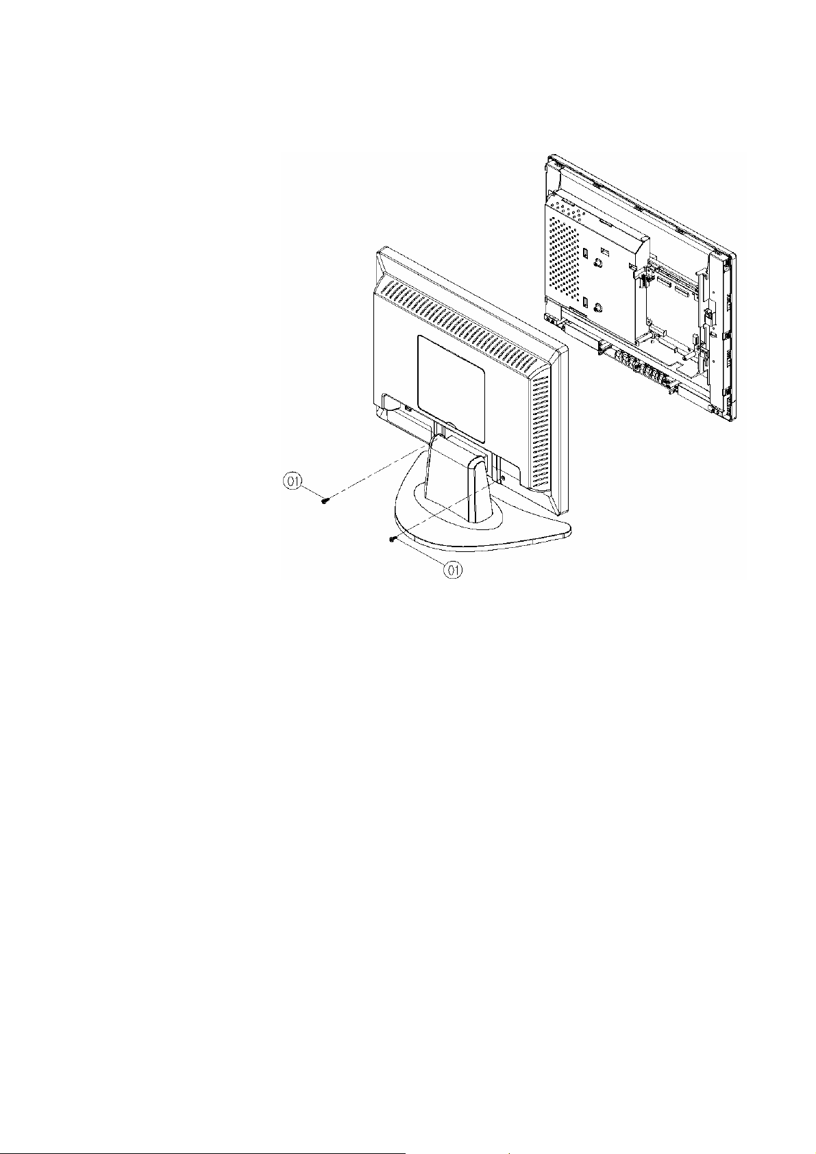
5. DISASSEMBLY INSTRUCTIONS
1.Stand and & rear cover removal
1) remove four large screw "1" from
the rear cover
2) remove the back cover
_____________________________________________________________________________________________________________________________
111503 Page 16
Confidential -
 Loading...