


MAXDA T A PLA TINUM SERVER
Mainboard
Users’ Manual
MAXDATA PLATINUM Server Mainboard Manual
1

2

Contents
1 Description.......................................................................................................9
Server Board Features ............................................................................................................. 9
Back Panel Connectors.......................................................................................................... 10
Server Board Connector and Component Locations ..............................................................11
Processor...........................................................................................................................11
Memory ............................................................................................................................ 12
Add-in Board Slots ................................................................................................................. 12
Video...................................................................................................................................... 13
SCSI Controller ...................................................................................................................... 14
IDE Controller ........................................................................................................................ 14
USB Interface ........................................................................................................................ 14
Network Controller ................................................................................................................ 14
Network T eaming Features ............................................................................................... 15
Adapter Fault Tolerance ..................................................................................................... 15
Preferred Primary Adapter ................................................................................................ 15
Mixed Adapter Teaming..................................................................................................... 15
Adaptive Load Balancing ................................................................................................... 15
Keyboard and Mouse............................................................................................................. 16
ACPI.................................................................................................................................. 16
Security ................................................................................................................................. 16
Security with Mechanical Locks and Monitoring .............................................................. 16
Software Locks ................................................................................................................. 16
Using Passwords .............................................................................................................. 17
Secure Mode .................................................................................................................... 17
Summary of Software Security Features .......................................................................... 17
2 Server Board Installation..............................................................................19
Tools and Supplies Needed ................................................................................................... 19
Before Y ou Begin ................................................................................................................... 19
Emissions Disclaimer ............................................................................................................19
Safety Cautions ..................................................................................................................... 19
Safety and Regulatory Compliance........................................................................................ 20
Minimum Hardware Requirements ....................................................................................... 20
Processor.......................................................................................................................... 20
Memory ............................................................................................................................ 20
Power Supply ....................................................................................................................20
Installation Notes................................................................................................................... 21
Installation Procedures .......................................................................................................... 21
Installing the I/O Gasket and Shield.................................................................................. 21
Attaching the Gasket to the I/O Shield.............................................................................. 21
Attaching the Label to the I/O Shield ................................................................................ 22
Installing the I/O Shield..................................................................................................... 22
Installing the Processor(s)................................................................................................. 23
Installing a Terminator ....................................................................................................... 26
Installing Memory ............................................................................................................. 26
Configuring Chassis Standoffs.......................................................................................... 28
Installing the Server Board................................................................................................ 29
Making Connections to the Server Board......................................................................... 30
Cable Routing ........................................................................................................................ 31
IDE or SCSI Cables ........................................................................................................... 31
Floppy and Front Panel USB Cables.................................................................................. 31
MAXDATA PLATINUM Server Mainboard Manual
3

Installing the COM2 Cable................................................................................................ 32
Finishing Up ...................................................................................................................... 32
Getting Started with Intel® Server Management (Optional) .................................................. 34
Installing the Service Partition .......................................................................................... 34
Preparing the Server to Boot from the CD-ROM Drive..................................................... 34
Creating the Service Partition ........................................................................................... 34
Formatting the Service Partition........................................................................................ 34
Installing your operating system....................................................................................... 34
Installing Intel® Server Control .......................................................................................... 35
3 Upgrading ......................................................................................................37
Tools and Supplies Needed ................................................................................................... 37
Cautions................................................................................................................................. 37
Memory ................................................................................................................................. 38
Processors............................................................................................................................. 38
Adding or Replacing a Processor ...................................................................................... 39
Removing a Processor...................................................................................................... 42
Installing or Removing a Terminator .................................................................................. 42
Replacing the Back up Battery............................................................................................... 43
4 Configuration Software and Utilities ..........................................................45
Hot Keys ................................................................................................................................ 45
Power-On Self-Test (POST) .................................................................................................... 46
Using BIOS Setup.................................................................................................................. 47
Record Your Setup Settings............................................................................................... 47
If You Cannot Access Setup .............................................................................................. 47
Starting Setup ................................................................................................................... 47
Setup Menus .................................................................................................................... 48
Main Menu........................................................................................................................ 49
Primary Master/Slave Submenu ....................................................................................... 50
Processor Settings Submenu............................................................................................ 51
Advanced Menu................................................................................................................ 51
Memory Reconfiguration Submenu.................................................................................. 52
PCI Configuration Submenu ............................................................................................. 52
On-board SCSI, LAN, VGA Submenu ................................................................................ 52
PCI slot Submenu ............................................................................................................. 53
PCI Device Submenu........................................................................................................ 53
I/O Device/Peripheral Configuration Submenu.................................................................. 53
Advanced Chipset Controller Submenu............................................................................ 54
Security Menu .................................................................................................................. 55
Server Menu .....................................................................................................................56
System Management Submenu....................................................................................... 57
Console Redirection Submenu ......................................................................................... 57
Boot Menu........................................................................................................................ 58
Boot Device Priority Submenu .......................................................................................... 58
Hard Drive Submenu......................................................................................................... 58
Removable Devices .......................................................................................................... 58
Exit Menu.......................................................................................................................... 59
Using the System Setup Utility.............................................................................................. 59
What You Need to Do........................................................................................................ 59
Running the SSU from the CD.......................................................................................... 59
Running the SSU Remotely via an Emergency Management Card.................................. 60
Starting the SSU ............................................................................................................... 60
Customizing the SSU........................................................................................................ 61
Launching a Task ............................................................................................................... 61
4
Contents

SEL Manager Add-in ......................................................................................................... 62
SDR Manager Add-in ........................................................................................................ 62
FRU Manager Add-in......................................................................................................... 63
Exiting the SSU.................................................................................................................63
FRUSDR Load Utility .............................................................................................................64
When to Run the FRUSDR Load Utility ............................................................................ 64
What You Need to Do........................................................................................................ 64
How You Use the FRUSDR Load Utility ........................................................................... 64
Upgrading the BIOS............................................................................................................... 67
Preparing for the Upgrade................................................................................................. 67
Recording the Current BIOS Settings ............................................................................... 67
Obtaining the Upgrade Utility ........................................................................................... 67
Creating a Bootable Diskette ............................................................................................ 67
Creating the BIOS Upgrade Diskette ................................................................................ 68
Upgrading the BIOS.......................................................................................................... 68
Recovering the BIOS......................................................................................................... 68
Changing the BIOS Language........................................................................................... 69
Using the Firmware Update Utility.................................................................................... 69
Making a BMC Firmware Update Diskette ....................................................................... 69
Making the Update Diskette Bootable ......................................................................... 69
Updating the BMC Firmware............................................................................................ 69
Recovering the BMC Firmware......................................................................................... 70
Making a FRUSDR File Update Diskette ........................................................................... 70
Making the Update Diskette Bootable ......................................................................... 70
Updating the FRUSDR Files.............................................................................................. 71
Using the Adaptec SCSI Utility .............................................................................................. 71
Running the SCSI Utility ................................................................................................... 71
5 Solving Problems ..........................................................................................73
Resetting the System ............................................................................................................73
Initial System Startup............................................................................................................. 73
Checklist ........................................................................................................................... 73
Running New Application Software........................................................................................74
Checklist ............................................................................................................................74
After the System Has Been Running Correctly ......................................................................74
Checklist ............................................................................................................................74
More Problem Solving Procedures........................................................................................ 75
Preparing the System for Diagnostic Testing .................................................................... 75
Verifying Proper Operation of Key System Lights ............................................................. 75
Confirming Loading of the Operating System................................................................... 75
Specific Problems and Corrective Actions............................................................................. 76
Power Light Does Not Light.............................................................................................. 76
No Characters Appear on Screen...................................................................................... 76
Characters Are Distorted or Incorrect............................................................................... 77
System Cooling Fans Do Not Rotate Properly .................................................................. 77
Diskette Drive Activity Light Does Not Light..................................................................... 77
Hard Disk Drive Activity Light Does Not Light .................................................................. 78
CD-ROM Drive Activity Light Does Not Light ................................................................... 78
Cannot Connect to a Server.............................................................................................. 78
Problems with Network.................................................................................................... 78
PCI Installation Tips ...........................................................................................................79
Problems with Application Software...................................................................................... 79
Bootable CD-ROM Is Not Detected ...................................................................................... 79
MAXDATA PLATINUM Server Mainboard Manual
5

6 Technical Reference.......................................................................................81
Server Board Jumpers........................................................................................................... 81
7 Regulatory and Integration Information .....................................................83
Product Regulatory Compliance ............................................................................................ 83
Product Saf ety Compliance ................................................................................................... 83
Product EMC Compliance ..................................................................................................... 83
Product Regulatory Compliance Markings ............................................................................ 83
Electromagnetic Compatibility Notices ................................................................................. 84
FCC (USA)......................................................................................................................... 84
Europe (CE Declaration of Conformity)............................................................................. 84
6
Contents

Figures
1. Back Panel Connectors ................................................................................................... 10
2. Server Board Connector and Component Locations........................................................11
3. Attaching the Gasket to the I/O Shield............................................................................ 21
4. Attaching the Label to the I/O Shield .............................................................................. 22
5. Installing the I/O Shield ................................................................................................... 22
6. Lifting the Locking Bar..................................................................................................... 23
7. Inserting the Processor................................................................................................... 24
8. Attaching the Heat Sink and Retention Clip .................................................................... 24
9. Locking the Heat Sink Retention Clip.............................................................................. 25
10. Attaching the Heat Sink Fan............................................................................................ 25
11. Installing a Terminator ..................................................................................................... 26
12. Installing Memory ........................................................................................................... 27
13. Configuring Chassis Standoffs ........................................................................................ 28
14. Placing the Server Board in the Chassis ......................................................................... 29
15. Making Connections to the Server Board....................................................................... 30
16. Routing Cables ................................................................................................................ 31
17. Routing the Floppy and USB Cables ............................................................................... 31
18. Installing the COM2 Cable .............................................................................................. 32
19. Making Back Panel Connections..................................................................................... 33
20. Raise the Locking Bar...................................................................................................... 39
21. Insert the Processor........................................................................................................ 40
22. Attach the Heat Sink and Retention Clip ......................................................................... 40
23. Lock the Heat Sink Retention Clip................................................................................... 41
24. Attach the Fan................................................................................................................. 41
25. Installing a Terminator ..................................................................................................... 42
26. Replacing the Back up Battery ........................................................................................ 43
27. Jumper Locations............................................................................................................ 81
Tables
1. Server Board Features ...................................................................................................... 9
2. Video Modes...................................................................................................................13
3. Software Security Features............................................................................................. 18
4. Configuration Utilities...................................................................................................... 45
5. Hot Keys.......................................................................................................................... 45
6. Configuration Jumper (CN42).......................................................................................... 81
7. Configuration Jumper (CN46).......................................................................................... 82
8. Configuration Jumper (CN47).......................................................................................... 82
9. Configuration Jumper (CN48).......................................................................................... 82
10. Configuration Jumper (CN49).......................................................................................... 82
11. Configuration Jumper (CN50).......................................................................................... 82
MAXDATA PLATINUM Server Mainboard Manual
7

8

1 Descr iption
Server Board Features
Table 1. Server Board Features
Feature Description
Processor
Memory (DRAM)
Video Memory 4 MB SDRAM of video memory.
PCI bus
Graphics Integrated onboard ATI Rage XL 32 bit SVGA controller.
SCSI
Network
System I/O
Form Factor
Up to two In tel® Pentium® III processors in a Socket-370 Flip Chip Pin Grid
Array (FC-PGA) pa ckage.
Six 72 bit sockets for 168-pin, 133 MHz, 3.3V, PC/133 compliant, registered,
ECC, SDRAM single-sided or double-sided memory modules (DIMM)
Two standard PCI (PCI-33/32 bit) expansion slots for add -in boards.Four PCI-
66 MHz/64 bit expansion slots.
Adaptec AIC-7899W dual channel Ul t ra160 SCSI, supporting onboard Ul t ra 2
(LVD) wide, Ul t ra-wide, and Ultra160 SCSI interfaces.
Integrated onboard NICs, an Intel® 82550 single chip PCI LAN controller for
10 or 100 MbpsTX Fast Ethernet networks. Two RJ-45 Ethernet connectors
at the I/O back pa nel.
PS/2-compatible keyboard and mouse ports, 6 pin DIN.Advanced parallel port,
supporting Enhanced Parallel Port (EPP), compatible 25 pin.VGA video port,
15 pin.Two serial ports, one 9 pin on the rear I/O and one through a 10 pin
header on the baseboard.Two RJ-45 Ethernet por ts.Four USB ports, three on
the rear I/O and one through a 10 pin h eader on the baseboard.
Server ATX form factor, ATX 2.03 compliant I/O.
MAXDATA PLATINUM Server Mainboard Manual
9
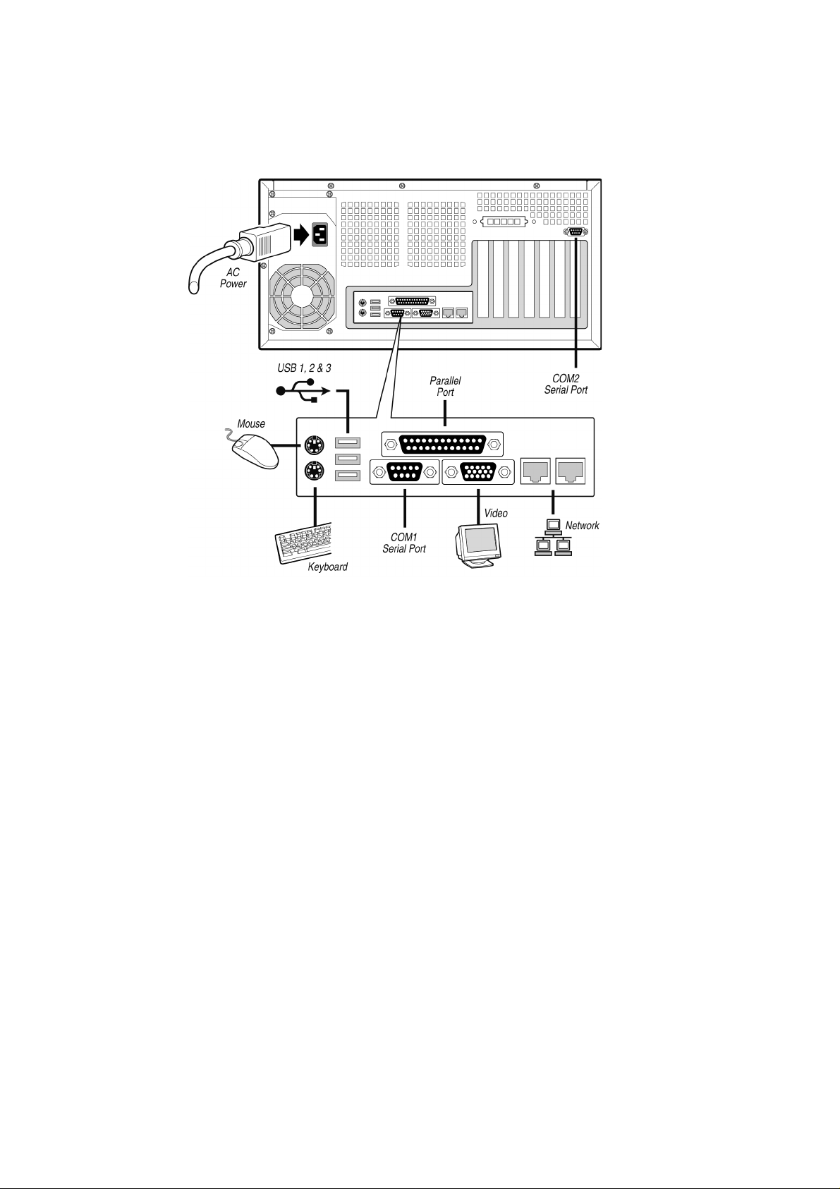
Back Panel Connectors
Figure 1. Back Panel Connectors
10
Description
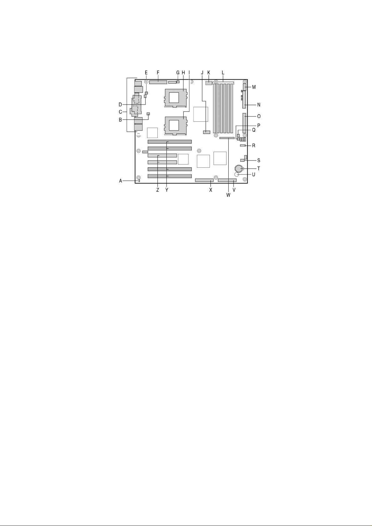
Server Board Connector and Component Locations
Figure 2. Server Board Connector and Component Locations
A. Chassis intrusion connector
B. CPU Fan 2
C. Back panel I/O ports
D. Fan 4
E. Fan 3
F. Main power connector
G. CPU Fan 1
H. CPU 1
I. CPU 2
J. COM2/EMP
K. +12 V CPU power connector
L. DIMMs
M. USB
N. Floppy drive connector
O. IDE
P. Fan 2
Q. Fan 1
R. Configuration jumper block CN42
S. Configuration jumper block CN46-CN49
T. Battery
U. Speaker
V. SCSI B
W. Front panel connector
X. SCSI A
Y. 66 MHz/64-bit PCI connectors
Z. 33 MHz/32-bit PCI connectors
Processor
The MAXDATA PLATINUM 1200/3200 server board accommodates one or two Intel
Pentium® III processors for the PGA370 socket. The processor external interface operates
at a maximum of 133 MHz.
When two processors are installed, both processors must be of identical bus/core speed.
When only one processor is installed, the other socket must ha v e an AGTL terminator card
installed.
®
MAXDATA PLATINUM Server Mainboard Manual
11

Memory
The MAXDATA PLATINUM 1200/3200 Ser ver Board contains six 168-pin DIMM sockets.
Memory is partitioned as three banks. DIMMs must be populated in identical pairs.
The MAXDATA PLATINUM 120 0/3200 Server Board supports up to six 3.3-V, registered
ECC SDRAM DIMMs that are compliant with the JEDEC PC133 specification. A wide range
of DIMM sizes are supported, including 64 MB, 1 28 MB, 256 MB , 512 MB , and 1 GB DIMMs.
The minimum supported memory configuration is 128 MB, using two identical 64 MB
DIMMs. The maximum configurable memory size is 6 GB using six 1 GB DIMMs.
The SDRAM interface runs at the same frequency as the processor bus. The memory
controller supports 2-way interlea ved SDRAM, memory scrubbing, single bit error correction
and multiple bit error detection. Memory can be implemented with either single-sided (one
row) or double-sided (two row) DIMMs.
✏ NOTE
Use DIMMs that have been tested for compatibility with the ser ver board. Contact your
sales representative or dealer for a current list of approved memory modules.
Add-in Board Slots
The server board has two full-length standard PCI (PCI-33/32 bit) connectors. PCI features:
• Bus speed up to 33 MHz
• 32 bit memory addressing
• 5 V signaling environment
• Burst transfers of up to 133 Mbps
• 8, 16, or 32 bit data transfers
• Plug and Play ready
• Parity enabled
The server board has four full-length PCI-66/64 connectors. PCI features:
• Bus speed up to 66 MHz
• 32 bit memory addressing
• 3.3 V signaling environment
• Burst transfers of up to 528 Mbps
• 8, 16, 32, or 64 bit data transfers
• Plug and Play ready
• Parity enabled
✏ NOTE
If you install a PCI-33 card into one of the PCI-66 slots, the bus speed for all two slots will be
lowered to 33 MHz.
12
Description

Video
The system has an integrated ATI Rage XL 32 bit high-performance SVGA subsystem that
supports the following:
• BIOS compatibility with all standard VGA modes
• 4 MB of video memory
• Pixel resolutions up to 1024 x 768 resolution in 8/1 6/24/32 bpp modes under 2D and up
to 800 x 600 resolution in 8/16/24/32 bpp modes under 3D
• Both CRT and LCD monitors up to 10 0 Hz vertical refresh rate
Table 2. Video Modes
2D Mode Refresh Rate (Hz) 2D Mo de Vide o Supp ort
640x480 60, 72, 75, 90, 100 Suppo rted Suppo rted Supported S upported
8 00x600 60, 70, 75, 90, 100 Supported Sup ported Suppo rted Suppo rted
1024x768 60, 72, 75, 90, 100 Suppo rted Suppo rted Supported Sup ported
1280 x102443, 60 Supported Supported Supported -
1280x1024 70, 72 Supported - Supported -
1600x1200 60, 66, 76, 85 Supported Supported -
3D Mode Refresh Rate (Hz)
640x480 60, 72, 75, 90, 100 Suppo rted Suppo rted Suppo rted Suppo rted
8 00x600 60, 70, 75, 90, 100 Supported Sup ported Sup ported -
1024x768 60, 72, 75, 90, 100 Suppo rted ---
1280 x102443, 60, 70, 72 ----
1600x1200 60, 66, 76, 85 ---
3D Mode Refresh Rate (Hz) 3D Mode Video Support with Z Buffer Disabled
640x480 60, 72, 75, 90, 100 Suppo rted Suppo rted Suppo rted Suppo rted
8 00x600 60, 70, 75, 90, 100 Supported Sup ported Sup ported Sup ported
1024x768 60, 72, 75, 90, 100 Suppo rted Suppo rted --
1280 x102443, 60, 70, 72 Supported ---
1600x1200 60, 66, 76, 85 Supported --
3D Mode Video Support with Z Buffer Enabled
-
-
-
MAXDATA PLATINUM Server Mainboard Manual
13

SCSI Controller
The embedded A daptec AIC-7899W dual function SCSI controller provides Ultra1 60 (LVDS),
(Ultra 2), and Ultra wide (SE) SCSI interfaces as two independent PCI functions.
The MAXDATA PLATINUM 1200/3200 baseboard provides active terminators, termination
voltage, resetable fuse, and protection diode for both SCSI c hannels. Onboard terminators
can be enabled/disabled using the BIOS setup menu.
IDE Controller
The system includes a single c hannel enhanced IDE 32 bit interf ace controller for intelligent
disk drives with disk controller electronics onboard. The controller has a connector located
on the system board that supports a master and a slave device.
The device controls:
• PIO, ATA-10 0 Synchronous DMA, and bus master IDE transfer modes
• Ultra DMA 66 capable
• Transfer rates up to 100 MB/s
• Master/slave IDE mode
• Up to two devices
USB Interface
The MAXD A T A PLA TINUM 1 200/3200 Server Board provides three e xternal USB connectors
on the rear I/O panel. T he external connectors are defined by the USB Specification, R evision
1.1. One additional USB connector is supported internally through a 10-pin header on the
server board that can be cabled to a front panel board. All four ports function identically and
with the same bandwidth.
Network Controller
The server board includes a 10BASE-T/100BASE-TX network solution based on the
Intel®82550 single chip F ast Ethernet PCI Bus Controller. As a PCI bus master , the controller
can burst data at up to 132 MB/s. The controller contains two receive and transmit FIFO buff ers
that prevent data ov erruns or underr uns while waiting for access to the PCI bus. The controller
has the following:
• 32 bit PCI bus master interface (direct drive of bus), compatible with PCI Bus Specification,
Revision 2.2
• Chained memory structure with improved dynamic transmit chaining for enhanced
performance
• Programmable transmit threshold for improved bus utilization
• Early receive interrupt for concurrent processing of receive data
• Onchip counters for network management
• Autodetect and autoswitching for 10 or 100 Mbps network speeds
• Support for both 10 Mbps and 100 Mbps networks, capable of full or half duplex, with
back-to-back transmit at 100 Mbps
• Integrated IP Security (IPSec) encryption engine
• Alert on LAN functionality
14
Description

Network T eaming Features
The network controller provides sev eral options for increasing throughput and fault tolerance
when running Windows® NT 4.0, Windows® 2000 or NetWare® 4.1x or newer:
• Adapter Fault Tolerance (AFT) - provides automatic redundancy for your adapter. If the
primary adapter fails, the secondary takes over. AFT works with any hub or switch.
• Adaptive Load B alancing (ALB) - creates a team of 2 - 4 adapters to increase transmission
throughput. Also includes AFT. Works with any 10Base-TX or 100Base-TX switch.
• Fast EtherChannel
and reception throughput. Also includes AFT. Requires an FEC-enabled switch.
®
(FEC) - creates a team of 2, 3 or 4 adapters to increase transmission
Adapter Fault Tolerance
Adapter Fault Tolerance (AFT) is a simple, effective, and fail-safe approach to increase the
reliability of server connections. AFT gives you the ability to set up link recovery to the
server adapter in case of a cable, port, or network interface card failure. By assigning two
PRO/100 Intelligent Server adapters as a team, AFT enables you to maintain uninterrupted
network performance.
AFT is implemented with two PRO/100 Intelligent Server adapters: a primary adapter and
a backup, or secondary, adapter. During normal operation, the backup will have transmit
disabled. If the link to the primary adapter fails, the link to the backup adapter automatically
takes over.
Preferred Primary Adapter
With multiple adapters installed, you can specify one as the Preferred Primary adapter. For
example if you have a server with a PRO/100 Intelligent Ser ver adapter as the primary
adapter and a PRO/1 00+ adapter as the secondary, y ou would w ant the PRO/100 Intelligent
Server adapter to be the preferred primary . In this scenario, if the PRO/1 00 Intelligent Server
adapter fails, the PRO/1 00+ will take ov er . T hen when the PRO/1 00 Intelligent Server adapter
is replaced, it will automatically revert to being the primary adapter in the team.
If a Pref erred Primary is not selected, PROSet will at tempt to select the best adapter , based
on adapter model and speed.
Mixed Adapt er Teaming
AFT supports up to four PRO/1000 or PRO/100 adapters per team, in any mix.
Adaptive Load Balancing
Adaptive Load B alancing (ALB) is a simple and efficient w ay to increase your server’ s transmit
throughput. With ALB you group PRO/1 00 Intelligent Server adapters in teams to provide an
increased transmit rate (up to 400 Mbps) using a maximum of four adapters. T he ALB sof tware
continuously analyzes transmit loading on each adapter and balances the rate across the
adapters as needed. Adapter teams configured for ALB also provide the benefits of AFT.
Receive rates remain at 100 Mbps.
T o use ALB, y ou must hav e two, three, or four PRO/100 Intelligent Server adapters installed
in your server or workstation and linked to the same network switch.
MAXDATA PLATINUM Server Mainboard Manual
15

Keyboard and Mouse
The ke yboard/mouse controller is PS/2-compatible. The server may be lock ed automatically
if there is no keyboard or mouse activity for a predefined length of time, if specified through
the System Set up Utility (SSU). Once the inactivity (lockout) timer has e xpired, the keyboard
and mouse do not respond until the previously stored password is entered.
ACPI
The MAXDATA PLATINUM 1200/3200 supports the Advanced Configuration and Power
Interface (ACPI) as defined by the ACPI 1.0b. An ACPI aware operating system can put the
system into a state where the hard drives spin down, the sy stem fans stop, and all processing
is halted. Howev er , the po wer supply will still be on and the processors will still be dissipating
some power, so the power supply fan and processor fans will still run.
The MAXD ATA PLATINUM 1200/3200 supports sleep states s0, s1, s4, and s5.
• s0: Normal running state.
• s1: Processor sleep state: No context will be lost in this state and the processor caches
will maintain coherency .
• s4: Hibernate or Save to Disk: The memory and machine state are saved to disk. Pressing
the power button or other wakeup e vent will restore the system state from the disk and
resume normal operation. This assumes that no hardware changes have been made to
the system while it was off.
• s5: Soft off: Only the RTC section of the chipset and the BMC are running in this state.
CAUTION
The system is off only when the AC power is disconnected.
Security
To help prevent unauthorized entry or use of the server, Intel® Server Control server management software monitors the system intrusion switch.
Security with Mechanical Locks and Monitoring
If installed, you can activate the c hassis intrusion alarm switc h. When the side door is opened,
the switch transmits an alarm signal to the server board, where BMC firmware and ser ver
management software process the signal. The system can be programmed to respond to an
intrusion by locking the keyboard, for example.
Software Locks
The BIOS Setup and the System Setup Utility (SSU) provide a number of security features
to prevent unauthorized or accidental access to the system. Once the security measures
are enabled, you can access the system only after you enter the correct password(s). For
example:
• Enable the keyboard lockout timer so that the server requires a password to reactivate
the keyboard and mouse after a specified time out period 1 to 120 minutes.
• Set and enable a supervisor password.
• Set and enable a user password.
• Set secure mode to prevent keyboard or mouse input and to prevent use of the front
panel reset and power switches.
• Activate a hot key combination to enter secure mode quickly.
• Disable writing to the diskette drive when secure mode is set.
• Disable access to the boot sector of the operating system hard disk drive.
16
Description

Using Passwords
You can set either the user password, the supervisor password, or both passwords. If only
the user password is set, you:
• Must enter the user password to enter BIOS Setup or the SSU.
• Must enter the user password to boot the server if Password on Boot is enabled in
either the BIOS Setup or SSU.
• Must enter the user password to exit secure mode.
If only the supervisor password is set, you:
• Must enter the supervisor password to enter BIOS Setup or the SSU.
• Must enter the supervisor password to boot the server if Password on Boot is enabled
in either the BIOS Setup or SSU.
• Must enter the supervisor password to exit secure mode.
If both passwords are set, you:
• May enter the user password to enter BIOS Set up or the SSU. Ho wev er , you will not be
able to change many of the options.
• Must enter the supervisor password if you want to enter BIOS Setup or the SSU and
have access to all of the options.
• May enter either password to boot the server if Password on Boot is enabled in either
the BIOS Setup or SSU.
• May enter either password to exit secure mode.
Secure Mode
Configure and enable the secure boot mode by using the SSU. When secure mode is in
effect:
• You can boot the server and the operating system will run, but you must enter the user
password to use the keyboard or mouse.
• You cannot turn off system power or reset the server from the front panel switches.
Secure mode has no effect on functions enabled via the Server Manager Module or power
control via the real time clock.
Taking the server out of secure mode does not change the state of system power. That is,
if you press and release the power switch while secure mode is in effect, the system will
not be powered of f when secure mode is later remo ved. Ho we ver, if the front panel power
switch remains depressed when secure mode is removed, the server will be powered off.
Summary of Software Security Features
The table below lists the software security features and describes what protection each
off ers. In general, to enable or set the features listed here, you must run the SSU and go to
the Security Subsystem Group, menu. The table also refers to other SSU menus and to the
Setup utility.
MAXDATA PLATINUM Server Mainboard Manual
17

Table 3. Software Security Features
erutaeFnoitpircseD
•
.edom
•
edomeruceS
otgnitirwelbasiD
etteksid
:edomerucesretneotwoH
erucesnimetsysehtsecalpyllacitamotuasdrowssapgnilbanednagnitteS
metsysehterucesnacuoy,)puteShguorht(noitanibmocyek-tohatesuoyfI
roftiawotevahtonoduoysnaemsihT.noitanibmocyekehtgnisserpybylpmis
nacrevresehT:edomerucesnisimetsysehtnehW.doireptuo-emitytivitcanieht
detpeccatonsitupnidraobyekdnaesuomtub,metsysgnitarepoehtnurdnatoob
-DCehtnidetcetedsiDCafi,emittoobtA.deretnesidrowssapresuehtlitnu
nehW.drowssaparofstpmorpmetsyseht,AevirdnietteksidaroevirdMOR
ehtselbasiddnaetteksidroDCmorfstoobrevreseht,deretnesidrowssapeht
eht,AevirdnietteksidroevirdMOR-DCehtniDConsierehtfI.edomeruces
delbanellA.edomerucesotniseogyllacitamotuadnaCevirdmorfstoobrevres
retnE:edomerucesevaeloT.emittoobtatceffeotniogserutaefedomeruces
.)s(drowssaptcerroceht
asselnuetteksidaotetirwromorftoobtonlliwrevreseht,edomerucesnI
nisirevresehtrehtehwetteksidotsseccatcetorpetirwoT.deretnesidrowssap
yficepsdna,snoitpOyppolF,unemniamputeSehtesu,tonroedomeruces
.ylnodaersasseccAyppolF
osdoireptuoemitateS
esuomdnadraobyektaht
.detpeccatoneratupni
ebnacneercs,oslA
otsetirwdna,deknalb
detibihniebnacetteksid
gnisuotsseccalortnoC
rosivrepustes:USSeht
drowssap
.repmujdrowssaPraelCehtegnahc
ehtotsseccalortnoC
:USSnahtrehtometsys
drowssapresutes
.repmujdrowssaPraelC
draobyektuohtiwtooB
.egassemasyalpsiddnatneserpsitifidraobyekeht
toobehtyficepS
ecneuqes
.)s(drowssaptcerrocehtretnE:ytivitcaemuseroT.)puteShguorht
.tupniesuomrodraobyekynagnitpeccaerofebdrowssapaeriuqer
onfI.setunim021ot1morffodoireptuoemitytivitcaninaelbanednayficepS
draobyekdetpmetta,doirepdeificepsehtrofsrucconoitcaesuomrodraobyek
ehtdna,knalboglliwyalpsidrotinomehT.detpeccaebtonlliwtupniesuomdna
delbaneeraserutaefytirucesesehtfi(detcetorpetirweblliwevirdetteksid
ates,noitarugifnocmetsysehtgnignahcrognittesotsseccalortnocoT
resudnarosivrepusehthtobfI.puteShguorhttielbanednadrowssaprosivrepus
ehtelbanerorevresehttoobotdesuebnacrehtie,delbaneerasdrowssap
ebotputeSwollalliwdrowssaprosivrepusehtylnotub,esuomro/dnadraobyek
ehtniD-LRTCsserproyrtneknalbaottiegnahc,drowssapaelbasidoT.degnahc
ehtnidnuofunemnoitpOdrowssaProsivrepuSehtfounemdrowssaPegnahC
,puteSsseccatonnacuoyfidrowssapehtraelcoT.puorGmetsysbuSytiruceS
hguorhttielbanednadrowssapresuates,metsysehtgnisuotsseccalortnocoT
ehtniD-LRTCsserproyrtneknalbaottiegnahc,drowssapaelbasidoT.puteS
ytiruceSehtnidnuofunemnoitpOdrowssaPresUehtfounemdrowssaPegnahC
ehtegnahc,puteSsseccatonnacuoyfidrowssapehtraelcoT.puorGmetsysbuS
ehterofeb,TSOPgniruD.draobyekatuohtiwrohtiwtoobnacmetsysehT
stsetdnastcetedyllacitamotuaSOIBeht,ecneuqestoobehtsetelpmocmetsys
erucesfI.redrotoobehtenimretedlliwputeSniyficepsuoytahtecneuqesehT
arofdetpmorpeblliwuoyneht,)tessidrowssapresua(delbanesiedom
ehtdnadelbanesiedomerucesfI.stoobyllufrevresehterofebdrowssap
lliwtubtoobylluflliwrevreseht,delbaneoslasinoitpo"edoMtooBeruceS"
18
Description

2 Server Boar d Installation
Tools and Supplies Needed
• Phillips (cross head) screwdriver (#1 bit and #2 bit)
• Flat blade screwdriver
• Needle nosed pliers
• Antistatic wrist strap and conductive foam pad (recommended)
Before Y ou Begin
Emissions Disclaimer
To ensure EMC compliance with your local regional rules and regulations, the final
configuration of your end system product may require additional EMC compliance testing.
For more information please contact your local MAXDATA Representative.
See “Regulatory and Integration Information” for product Safety and EMC regulatory
compliance information. This is an FCC Class A device. Integration of it into a Class B c hassis
does not result in a Class B device.
Safety Cautions
CAUTION
Electrostatic discharge (ESD) & ESD protection: ESD can damage disk drives, boards, and
other parts. We recommend that you perform all procedures in this chapter only at an ESD
workstation. If one is not available, provide some ESD protection by wearing an antistatic
wrist strap attached to chassis ground∫any unpainted metal surface∫on your ser ver when
handling parts.
ESD and handling boards: Alwa ys handle boards carefully . They can be extremely sensitive
to ESD. Hold boards only b y their edges. Af ter removing a board from its protective wrapper
or from the server, place the board component side up on a grounded, static free surface.
Use a conductive foam pad if available but not the board wrapper. Do not slide board over
any surface.
MAXDATA PLATINUM Server Mainboard Manual
19

Safety and Regulatory Compliance
See “Regulatory and Integration Information” for product Safety and EMC regulatory
compliance information.
Intended uses: T his product was ev aluated for use in servers that will be installed in offices,
computer rooms, and similar locations. Other uses require further evaluation.
EMC testing: Before computer integration, make sure that the chassis, power supply, and
other modules have passed EMC testing using a server board with a microprocessor from
the same family (or higher) and operating at the same (or higher) speed as the microprocessor
used on this server board.
Server board diagram label provided: Place the label inside the chassis in an easy-to-see
location, preferably oriented similarly to the server board.
Minimum Hardware Requirements
To avoid integration difficulties and possible board damage, your system must meet the
following minimum requirements.
Processor
Minimum of one 1.0 GHz Intel® Pentium® III processor with 256 cache support.
Memory
Minimum of two identical 3.3 V, ECC, PC/133 compliant, registered SDRAM, 168-pin gold
DIMMs. Minimum size: 64 MB. DIMMs must be populated in identical pairs.
Power Supply
Minimum of 275 W with 1.2 A +5 V standby current (in order to support Wak e On LAN®(WOL))
and 12+ V CPU power support [A TX]. Y ou must pro vide standby current, or the board will not
boot.
20
Server Board Installation
Installation Notes
Installation Process Quick Reference
Step Where the information is located
Install the primary processor This guide
Install the secondary processor (optional) This guide
Install memory This guide
Remove the access cover Your chassis manual
Install the I/O shield This guide
Rearrange the standoffs This guide
Install the server board This guide
Connect cables to the server board This guide and your chassis manual
Finish setting up your chassis Your chassis manual
Installation Procedures
Installing the I/O Gasket and Shield
✏ NOTE
An A TX 2.03-compliant I/O shield is pro vided with the server board. T he shield is required by
Electromagnetic Interference (EMI) regulations to minimize EMI. If the shield does not fit
the chassis, obtain a properly sized shield from the chassis supplier.
The shield fits the rectangular opening in the back of a chassis. The shield has cutouts that
match the I/O ports. Install the shield from inside the chassis.
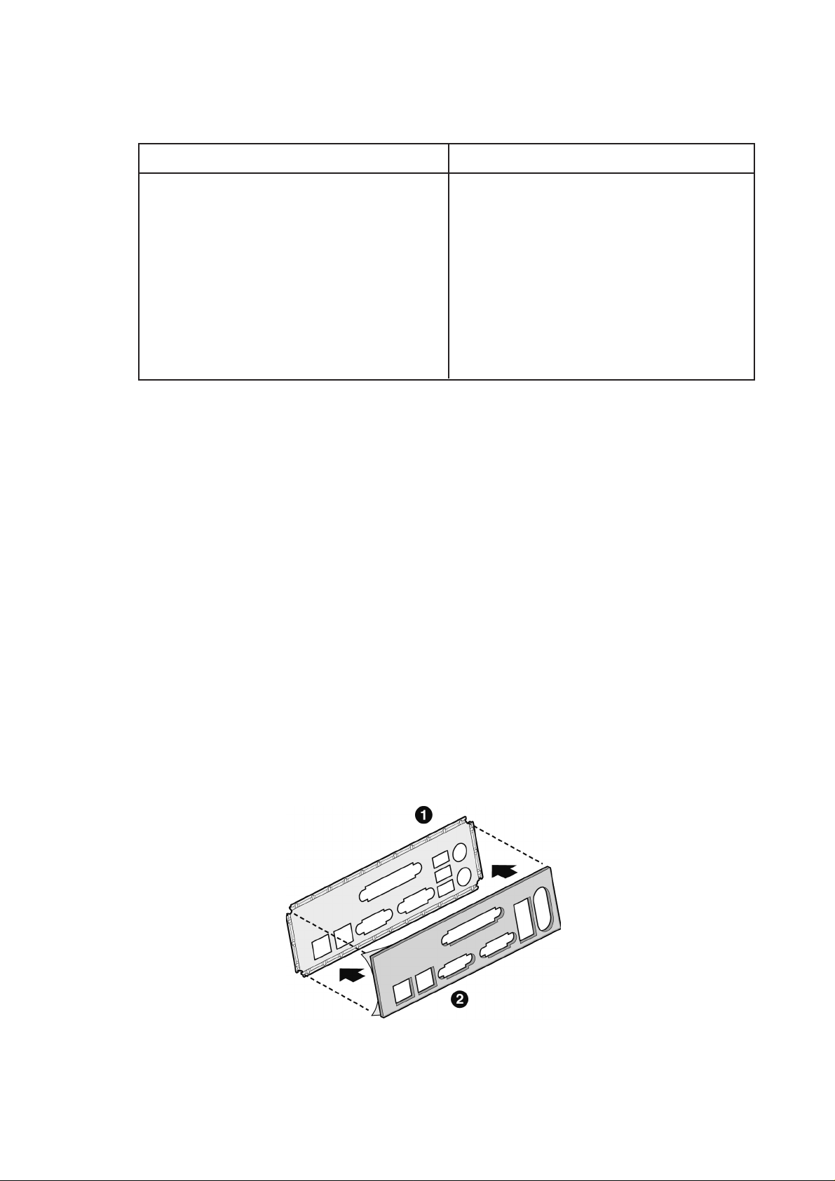
Attaching the Gasket to the I/O Shield
1. Remove the two backing strips from the gasket.
2. Press the gasket onto the inside face of the I/O shield as show.
Figure 3. Attaching the Gasket to the I/O Shield
MAXDATA PLATINUM Server Mainboard Manual
21
Attaching the Label to the I/O Shield
1. Remove the backing from the label included with your server board.
2. Press the label onto the outside face of the I/O shield.
Figure 4. Attaching the Label to the I/O Shield
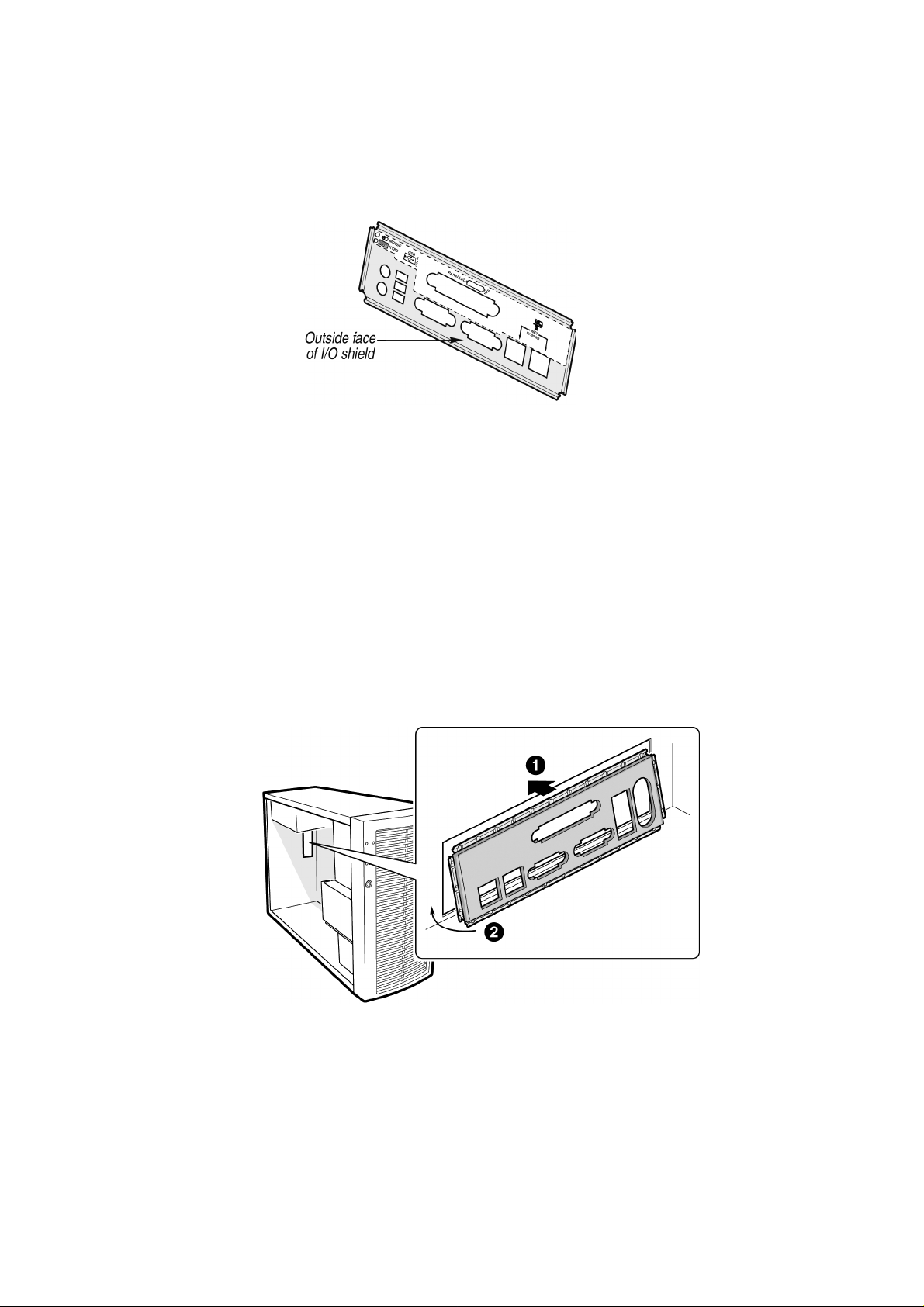
Installing the I/O Shield
1. Position one edge so that the dot ted groove is outside the c hassis wall, and the lip of the
shield rests on the inner chassis wall.
2. Hold the shield in place, and push it into the opening until it is seated. Make sure the I/O
shield snaps into place all the way around.
22
Figure 5. Installing the I/O Shield
Server Board Installation

Installing the Processor(s)
CAUTIONS
If only one processor is to be used, it must be installed in the Primary Processor Socket
(CPU1) and a Terminator must be installed in the Secondary Processor Socket (CPU2).
If you are adding a second processor to your system, you must verify that the second
processor is identical to the first Intel
®
Pentium® III, same voltage and speed.
This server board has “zero-insertion-force” sockets. If processor does not drop easily into
socket holes, make sure the lever is in the full-upright position.
1 . Observe the safety and ESD precautions at the beginning of this chapter and the additional
precautions given here.
2. When installing the primary processor, lif t the loc king bar on the processor soc ket (CPU1)
as shown. If adding a second processor, lift the locking bar on the secondary processor
socket (CPU2), and repeat steps 3 through 7 after installing the primary processor.
Figure 6. Lifting the Locking Bar
3. Align the pins of the processor with the soc k et and insert the processor into the soc ket.
Lower the locking bar completely.
MAXDATA PLATINUM Server Mainboard Manual
23
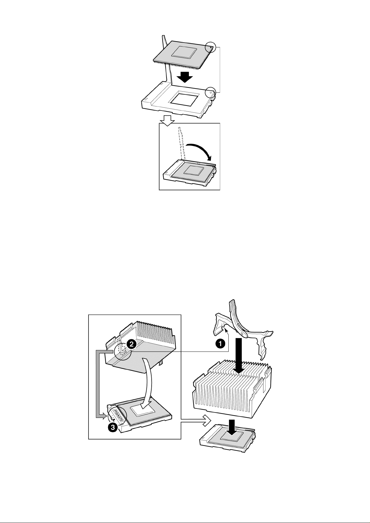
Figure 7. Inserting the Processor
4. B efore inserting the retention clip into the heat sink slot, make sure the plastic pin (see
1 below) is aligned with the heat sink notc h (see 2 below). Align the notc hed side of the
heat sink (see 2 below) with the edge of the socket containing the “PG370” designation
(see 3 below) and place onto the processor as shown.
24
Figure 8. Attaching the Heat Sink and Retention Clip
Server Board Installation
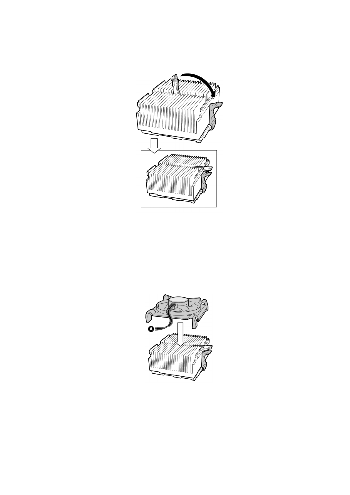
5. Close the heat sink retention clip as shown. Use slow, constant pressure to close the
retention clip lever.
Figure 9. Locking the Heat Sink Retention Clip
6. Attach the fan heat sink clip to the processor socket as shown.
Figure 10. Attaching the Heat Sink Fan
7. Connect the processor fan cable(s) to the correct connector in the “Making Connections
to the Server Board” section below.
MAXDATA PLATINUM Server Mainboard Manual
25

Installing a Terminator
If only one processor is to be installed, a terminator must be installed in Secondary Processor
Socket (CPU 2).
1. Align the corner mark on the terminator with the handle side of the processor socket.
2. Close and latch the socket lever.
Figure 11. Installing a Terminator
✏ NOTE
It is not necessary to install a heat sink on the processor terminator.
Installing Memory
The MAXDATA PLATINUM 1200/3200 Server Board contains six 1 68-pin DIMMs. Memory
is partitioned as three banks. DIMMs must be populated in identical pairs.
The MAXDATA PLATINUM 120 0/3200 Server Board supports up to six 3.3-V, registered
ECC SDRAM DIMMs that are compliant with the JEDEC PC133 specification. A wide range
of DIMM sizes are supported, including 64 MB, 1 28 MB, 256 MB , 512 MB , and 1 GB DIMMs.
The minimum supported memory configuration is 128 MB, using two identical 64 MB
DIMMs. The maximum configurable memory size is 6 GB using six 1 GB DIMMs.
The SDRAM interface runs at the same frequency as the processor bus. The memory
controller supports 2-way interlea ved SDRAM, memory scrubbing, single bit error correction
and multiple bit error detection. Memory can be implemented with either single-sided (one
row) or double-sided (two row) DIMMs.
✏ NOTE
Use DIMMs that have been tested for compatibility with the ser ver board. Contact your
sales representative or dealer for a current list of approved memory modules.
26
Server Board Installation

1. Open both DIMM socket levers
2. Insert DIMM making sure the connector edge of the DIMM aligns correctly with the
slot.
3. Check that socket levers are securely latched. DIMMs must be populated in identical
pairs.
Figure 12. Installing Memory
MAXDATA PLATINUM Server Mainboard Manual
27

Configuring Chassis Standoffs
If your chassis does not have standoffs placed as shown below, you must rearrange them
so they matc h the holes in the server board. Failure to properly rearrange the metal standoffs
may cause the server board to malfunction and may permanently damage it. Your chassis
may be different from the illustration.
For the MAXDATA PLATINUM chassis:
1 . Install standoffs in positions 7 and 1 7. Standoff numbering in other c hassis may be diff erent.
Standoffs are included with your chassis.
28
Figure 13. Configuring Chassis Standoffs
Server Board Installation

Installing the Server Board
1. Place the board into the chassis, making sure that the back panel I/O shield openings
and chassis standoffs align correctly.
2. Attach the board with the screws included with your chassis.
Figure 14. Placing the Server Board in the Chassis
MAXDATA PLATINUM Server Mainboard Manual
29

Making Connections to the Serv er Board
Figure 15. Making Connections to the Server Board
A. Main power connector
B. +12 V CPU Power
C. Front Panel USB
D. Floppy disk drive connector
E. ATA 100/IDE Chassis Fans
F. Front Panel connector
G. SCSI B
H. SCSI A
I. CPU2 Fan
J. Chassis Fans
K. CPU1 Fan
L. COM2/EMP
M. Chassis Intrusion
N. Chassis Fans
30
Server Board Installation

Cable Routing
To ensure proper air flow within the chassis, follow the cable routing guidelines below.
IDE or SCSI Cables
Cables that connect to devices in the lower device bays should be routed around the epac
as shown below.
1. Route cables as shown.
2. Replace the top half of the epac.
Figure 16. Routing Cables
Floppy and Front Panel USB Cables
Route the floppy drive cable as shown.
Floppy Disk Cable
Route the floppy drive
cable as shown.
Figure 17. Routing the Floppy and USB Cables
MAXDATA PLATINUM Server Mainboard Manual
31

Installing the COM2 Cable
For the MAXDATA PLA TINUM chassis, you can connect the COM2 serial port cable to either
the front or back panels. Connecting it to the back panel is illustrated below.
1. Install the COM2 cable by inserting it into the c hassis bac k panel cutout and attaching it
as shown.
2. At tac h the other end of the COM2 connector located on y our server board between the
CPU2 Processor soc ket and the DIMMs. See “Making Connections to the Server Board”
for the exact COM2 connector location.
Figure 18. Installing the COM2 Cable
32
Server Board Installation

Finishing Up
WARNING
An electrical shock hazard exists if the chassis cov er is not replaced before connecting the
chassis AC power.
1. Install the chassis cover according to the instructions for your chassis.
2. See your chassis documentation to complete rack or pedestal installation.
3. Connect the keyboard, mouse and monitor cables to the back panel.
4. Connect the power cable to the back panel and to an AC outlet.
Figure 19. Making Back Panel Connections
MAXDATA PLATINUM Server Mainboard Manual
33

Getting Star ted with Int el® Server Management (Optional)
Intel® Server Control and the hard drive Service Partition provide real-time monitoring and
alerting for your SDS2 server hardware, emergency remote management, and remote server
setup. Intel® Server Control is implemented by installing it within client-server architecture.
The Service Partition provides you with the ability to remotely access a local partition on the
server and to identify and diagnose server health issues. Remote access is provided through
either a modem or network connection.
To get st arted with Intel
the system’s operating system, and finally Intel® Server Control. The information here
describes installation on a system running a Microsoft Windows® operating system.
Installing the Service P artition
Installing the Service Partition consists of three tasks:
• Preparing the server to boot from the CD-ROM drive
• Creating the Service Partition
• Formatting the Service Partition
Preparing the Server to Boot from the CD-ROM Drive
1. Insert the Intel® Server Board SDS2 Resource CD into the server’s CD-ROM drive.
®
Server Management, you install the Service Partition first, then
2. Restart the server.
3. Press <F2> at the prompt to enter the BIOS setup utility during the boot cycle.
4. Select Boot Menu.
5. In Boot Device Priority, press the <+> key to move ATAPI
priority than the system hard drive.
6. Press the <F10> key to save the set tings. Af ter pressing this ke y , the system resets and
boots from the CD-ROM drive.
®
CD-ROM device higher in
Creating the Service Partition
7. From the CD-ROM menu, select Utilities and press the <Enter> key.
8. Select Run Service Partition Administrator and press the <Enter> key.
9. From the list of available items, select Create Service Partition-first time.
10. Follow the instructions that appear on the screen. These instructions prompt you to
reboot the server. It will reboot from the CD-ROM.
Formatting the Service Partition
11. After the system reboot, select the Utilities menu and press the <Enter> key.
12. Select Run Service Partition Administrator and press the <Enter> key.
13. Select Format Service Partition and Install Software.
14. Remove the System Resource CD from the CD-ROM drive and exit from the menu
screen. You can now install the server’s operating system.
Installing your operating system
Install your operating system now.
34
Server Board Installation

Installing Intel® Server Contr ol
15. Insert the Intel® Server Board SDS2 Resource CD into the system’s CD-ROM drive and
wait for the auto-launcher to display a start-up web page local to the System Resource CD.
16. F rom the start-up web page, open server management in the blue menu on the lef t side
of the screen.
17. Open make a selection in the green box.
18. Choose to either view the Intel
software installation.
19. To continue with the inst allation, click on Intel
After clicking on run installer, follow the screen instructions.
®
Server Control Installation Guide or to proceed with the
®
Server Control and then on run installer.
MAXDATA PLATINUM Server Mainboard Manual
35

36

3 Upgrading
Tools and Supplies Needed
• Phillips (cross head) screwdriver (#1 bit and #2 bit)
• Jumper removal tool or needle nosed pliers
• Pen or pencil
• Antistatic wrist strap and conductive foam pad (recommended)
Cautions
These warnings and cautions apply throughout this c hapter . Only a tec hnically qualified person
should configure the server board.
CAUTION
System pow er on/of f: T he power but ton DOES NO T turn of f the system A C power . T o remo ve
power from system, you must unplug the AC power cord from the wall outlet. Make sure
the A C power cord is unplugged bef ore you open the chassis, add, or remo ve any components.
Hazardous conditions, devices & cables: Hazardous electrical conditions may be present on
power , telephone, and communication cables. T urn of f the server and disconnect the power
cord, telecommunications systems, networks, and modems attached to the server before
opening it. Otherwise, personal injury or equipment damage can result.
Electrostatic discharge (ESD) & ESD protection: ESD can damage disk drives, boards, and
other parts. We recommend that you perform all procedures in this chapter only at an ESD
workstation. If one is not available, provide some ESD protection by wearing an antistatic
wrist strap attac hed to chassis ground - any unpainted metal surface - on your server when
handling parts.
ESD and handling boards: Alwa ys handle boards carefully . They can be extremely sensitive
to ESD. Hold boards only b y their edges. Af ter removing a board from its protectiv e wrapper
or from the server, place the board component side up on a grounded, static free surface.
Use a conductive foam pad if available but not the board wrapper. Do not slide board over
any surface.
Installing or removing jumpers: A jumper is a small plastic encased conductor that slips ov er
two jumper pins. Some jumpers have a small tab on top that you can grip with y our fingertips
or with a pair of fine needle nosed pliers. If your jumpers do not have such a tab, take care
when using needle nosed pliers to remove or install a jumper; grip the narro w sides of the
jumper with the pliers, never the wide sides. Gripping the wide sides can damage the
contacts inside the jumper, causing intermittent problems with the function controlled by
that jumper. Take care to grip with, but not squeeze, the pliers or other tool you use to
remove a jumper, or you may bend or break the stake pins on the board.
MAXDATA PLATINUM Server Mainboard Manual
37

Memory
The MAXDATA PLATINUM 1200/3200 Server Board contains six 1 68-pin DIMMs. Memory
is partitioned as three banks. DIMMs must be populated in identical pairs.
The MAXDATA PLATINUM 120 0/3200 Server Board supports up to six 3.3-V, registered
ECC SDRAM DIMMs that are compliant with the JEDEC PC133 specification. A wide range
of DIMM sizes are supported, including 64 MB, 1 28 MB, 256 MB , 512 MB , and 1 GB DIMMs.
The minimum supported memory configuration is 128 MB , using two identical 64 MB DIMMs.
The maximum configurable memory size is 6 GB using six 1 GB DIMMs.
The SDRAM interface runs at the same frequency as the processor bus. The memory
controller supports 2-way interlea ved SDRAM, memory scrubbing, single bit error correction
and multiple bit error detection. Memory can be implemented with either single-sided (one
row) or double-sided (two row) DIMMs.
✏ NOTE
Use DIMMs that have been tested for compatibility with the ser ver board. Contact your
sales representative or dealer for a current list of approved memory modules.
Processors
WARNING
If the server has been running, any installed processor and heat sink on the processor
board(s) will be hot. T o av oid the possibility of a burn, be careful when removing or installing
server board components that are located near processors.
38
Upgrading

CAUTION
Processor must be appropriate: You may damage the server if you install a processor that is
inappropriate for your server. Make sure your ser ver can handle a newer, faster processor
(thermal and power considerations).
ESD and handling processors: Reduce the risk of electrostatic discharge (ESD) damage to
the processor by doing the following: (1) Touch the metal chassis before touching the
processor or server board Keep part of your body in contact with the metal chassis to dissipate
the static charge while handling the processor. (2) Avoid moving around un-necessarily.
Adding or Replacing a Processor
If you are adding a second processor to your system, y ou must first remo v e the terminator
from the secondary processor socket. The second processor must be compatible with the
first processor.
1 . Observe the safety and ESD precautions at the beginning of this chapter and the additional
cautions given here.
2. Remove the side cover (see your system or chassis documentation for instructions).
Raise the locking bar on the socket.
Figure 20. Raise the Locking Bar
3. Aligning the pins of the processor with the soc k et, insert the processor into the socket.
Lower the locking bar completely.
MAXDATA PLATINUM Server Mainboard Manual
39

Figure 21. Insert the Processor
4. Before inserting the retention clip into the heat sink slot, make sure the plastic pin
located at 1 is aligned with the heat sink notc h at 2. Align the notched side of the heat
sink 2 with the edge of the socket containing the “PG370” designation 3 and place
onto the processor as shown below.
40
Figure 22. Attach the Heat Sink and Retention Clip
Upgrading

5. Lock the heat sink clip to the processor socket.
Figure 23. Lock the Heat Sink Retention Clip
6. Install the heat sink fan by snapping it into the top of the heat sink as shown.
Figure 24. Attach the Fan
MAXDATA PLATINUM Server Mainboard Manual
41

Removing a Processor
1 . Observe the safety and ESD precautions at the beginning of this chapter and the additional
cautions given here.
2. Unplug the heat sink fan.
3. Detach the heat sink clip from the processor soc k et. See the documentation that shipped
with your processor for more detail.
4. Remove the heat sink from the processor.
5. Raise the locking bar on the socket.
6. Remove the processor from the socket.
7. If you removed the processor from the secondary socket and are not replacing it, you
must install a terminator in its place.
Installing or Removing a Terminator
1 . Observe the safety and ESD precautions at the beginning of this chapter and the additional
cautions given here. Raise the locking bar on the socket.
2. Aligning the corner mark on the terminator with the “handle-side ” of the processor socket,
insert the terminator into the soc ket.
3. Lower the locking bar completely.
Do these steps in reverse to remove the terminator.
Figure 25. Installing a Terminator
✏ NOTE
It is not necessary to install a heat sink on the processor terminator.
42
Upgrading

Replacing the Back up Battery
The lithium battery on the server board powers the real time clock (RTC) for up to 10 years
in the absence of power . When the battery starts to weaken, it loses voltage, and the server
settings stored in CMOS RAM in the RTC (for example, the date and time) may be wrong.
Contact your customer service representative or dealer for a list of approved devices.
WARNING
Danger of explosion if bat tery is incorrectly replaced. Replace only with the same or equivalent
type recommended by the equipment manufacturer. Discard used batteries according to
manufacturer’s instructions.
1. Observe the safety and ESD precautions at the beginning of this chapter.
2. Open the chassis.
3. Insert the tip of a small flat bladed screw driver , or equiv alent, under the tab in the plastic
retainer. Gently push down on the screwdriver to lift the battery.
4. Remove the battery from its socket.
5. Dispose of the battery according to local ordinance. Remove the new lithium battery
from its package, and, being careful to observe the correct polarity , insert it in the bat tery
sock et.
6. Reinstall the plastic retainer on the lithium battery socket.
7. Close the chassis.
8. Run Setup to restore the configuration settings to the RTC.
Figure 26. Replacing the Back up Battery
MAXDATA PLATINUM Server Mainboard Manual
43

44

4 Configuration Sof tware and Utilities
This c hapter describes the P ow er-On Self-T est (POS T) and server configuration utilities. The
table below briefly describes the utilities.
Table 4. Configuration Utilities
Utility Description a n d brief proc ed ure
If the system does not have a diskette drive, or the drive is disabled or
misconfigured, use Setup to enable it.Or, you can move t he CMOS jumper
BIOS Setu p
System Setup Utility (SSU)
on the server board from the default setting (Protect CMOS memory) to the
Clear setting; this will allow most server configurations to boot. Then run the
SSU to configure the server.
Use for viewing and clearing the system event log, viewing the system
management FRU information, or viewing the system management SDR
repository.
FRUSDR Load Utility
BIOS Upgrade Utility Use to upgrade the BIOS.
Firmware Update Utility Use t o update the Firmware.
Using the Adaptec SCSI Utility
Use t o upda te the Field Replacement Unit (FRU), Sensor Data Record (SDR),
and SM BIOS (SMB) flash components.
Use t o configure or view the settings of the SCSI host adapters and onboard
SCSI devices in the server.
Hot Keys
Use the keyboard’s numeric pad to enter numbers and symbols.
Table 5. Hot Keys
To do thi s : Press these keys
Clear memory and reload the
operating system this is a
system reset.
<Ctrl+Alt+Del>
Secure your system immediately.
MAXDATA PLATINUM Server Mainboard Manual
<Ctrl+Alt>+hotkey (Set yo ur hot key combination with Setup.)
45

Power-On Self-Test (POST)
Each time you turn on the system, POST starts running. POST checks the server board,
processor, memory, keyboard, and most installed peripheral devices. During the memor y
test, POST displays the amount of memory that it is able to access and test. The length of
time needed to test memory depends on the amount of memory installed. POST is stored
in flash memory.
1. Turn on your video monitor and server. After a few seconds POST begins to run.
2. After the memory test, these screen prompts and messages appear:
Press <F2> key if you want to run SETUP
If you do not press <F2> and do NOT have a device with an operating system loaded,
the above message remains for a few seconds while the boot process continues, and
the system beeps once. Then this message appears:
Operating system not found
If you do not press <F2> and DO have an operating system loaded, the boot process
continues, and this message appears:
Press <Ctrl><A> to enter SCSI Utility
4. Press <Ctrl+A> if there are SCSI devices installed. When the utility opens, follow the
displayed instructions to configure the onboard SCSI host adapter settings and to run
the SCSI utilities. Also see “Using the Adaptec SCSI Utility” on page 71. If you do not
enter the SCSI utility, the boot process continues.
5. Press <Esc> during POS T to pop up a boot menu when POS T finishes. F rom this menu
you can choose the boot device or enter BIOS Setup.
After POST completes, the system beeps once.
What appears on the screen after this depends on whether you have an operating system
loaded and if so, which one.
If the system halts before POST completes running, it emits a beep code indicating a fatal
system error that requires immediate at tention. If POST can displa y a message on the video
display screen, it causes the speaker to beep twice as the message appears.
Note the screen display and write down the beep code you hear; this information is useful
for your service representative. For a listing of beep codes and error messages that POST
can generate, see the “Solving Problems” chapter in this manual.
46
Configuration Software and Utilities

Using BIOS Setup
This section describes the BIOS Setup options. Use Set up to change the server configuration
defaults. Y ou can r un Setup with or without an operating system being present. Set up stores
most of the configuration values in bat tery back ed CMOS; the rest of the v alues are stored
in flash memory. The values take ef fect when you boot the server . POS T uses these values
to configure the hardware; if the values and the act ual hardware do not agree, POST generates
an error message. You must then run Setup to specify the correct configuration.
Record Your Setup Settings
If the default values ever need to be restored (after a CMOS clear, for example), you must
run Setup again. Referring to the worksheets could make your task easier.
If You Cannot Access Setup
If the diskette drive is misconfigured so that you cannot access it to run a utility from a
disket te, you ma y need to clear CMOS memory. Y ou will need to open the server, change a
jumper setting, use Setup to check and set diskette drive options, and change the jumper
back. For a step-by-step procedure, see Chapter 5, under the heading, “CMOS Jumper.”
Starting Setup
You can enter and start Setup under several conditions:
When you turn on the server, after POST completes the memory test
• When you reboot the server by pressing <Ctrl+Alt+Del> while at the DOS operating
system prompt
• When you have moved the CMOS jumper on the server board to the “Clear CMOS”
position (enabled); for the procedure, see Chapter 5, under the heading “CMOS Jumper”
In the three conditions listed above, after rebooting, you will see this prompt:
Press <F2> to enter SETUP
✏ NOTE
If the BIOS setup option “POST Diagnostic Screen” is enabled (Default), you will not see
the message “P ress <F2> to enter SE TUP”. T his message is hidden b y the Manuf act urer’s
Splash screen. To see the message, press the <ESC> key while the splash screen is display ed.
This will temporarily disable the splash screen allowing you to see the message.
In a fourth condition, when CMOS/NVRAM has been corrupted, y ou will see other prompts
but not the <F2> prompt:
Warning: cmos checksum invalid
Warning: cmos time and date not set
In this condition, the BIOS will load default values for CMOS and attempt to boot.
MAXDATA PLATINUM Server Mainboard Manual
47

Setup Menus
To : Press
Get general help
Move between menus
Go to the previous item
Go to the n ext Item
Change t he value of an item + or -
Select an item or display a submenu <Enter>
Leave a submenu or exit Setup <Esc>
Reset t o Setup defaults <F9>
Save and exit Setup
When you see this: What it means
On scree n, an optio n is shown
but you cannot select it or move
to that field.
On screen, the phrase Press
Enter appears next to the option.
You cannot change or configure the option in that menu scre en. Either the
option is autoconfigured or autodetected, or you must use a different Setup
screen.
Press <Enter> to display a submenu that is eithe r a separate full screen
menu or a popup menu wit h one or mor e ch oic es .
<F1> or
<Alt+H>
<− −>
−>
−>
<F10>
The rest of this section lists the features that display onscreen after you press <F2> to
enter Setup. Not all of the option choices are described, because (1) a few are not user
selectable but are displayed for y our information, and (2) many of the choices are relatively
self explanatory.
48
Configuration Software and Utilities

Main Menu
You can make the following selections on the Main Menu itself. Use the submenus for
other selections.
Feature Choices Description
System Time HH:MM:SS Sets the sys tem time
System Date MM/DD/YYYY Sets the system date
Diskette A
Diskette B
Hard Disk Pre-Delay
Primary Master <Enter>Enters submenu
Primary Slave <Enter>Enters submenu
Processor <Enter>Enters submenu
Language
Disabled
1.44/1.25 MB
Disabled
1.44/1.25 MB
Disabled
3 Se conds
6 Se conds
9 Se conds
12 Seconds
15 Seconds
21 Seconds
30 Seconds
English (US)
Français
Deutsch
Italiano
Español
Selects the disket te type
Selects the disket te type
Adds a delay before first access of the hard drive
Selects which language BIOS displays
MAXDATA PLATINUM Server Mainboard Manual
49

Primary Master/Slave Submenu
Feature Choices Description
Auto
None
CD-ROM
Typ e
Mult-Sector Transfers
ATAPI Removable
IDE Removable
Other ATAPI
User
Disabled
2 Sectors
4 Sectors
8 Sectors
16 Sectors
Select the type of device that is attached to the IDE channel.If
User is selected, you will need to enter the parameters of the
IDE device (cylinders, heads and sectors).
Specifies the number of sectors that are transferred per block
during multiple sector transfers.
LBA Mode Control
32 Bit I/O
Transfer Mode
Primary Slave <Enter> Enters submenu
Processor <Enter> Enters submenu
Language
Disabled
Enabled
Disabled
Enabled
Standard
Fast PIO 1
Fast PIO 2
Fast PIO 3
Fast PIO 4
FPIO 3 / DMA 1
FPIO 4 / DMA 2
<Enter> Enters submenu
English (US)
Français
Deutsch
Italiano
Español
Enables large block addressing.
Enables 32 bit IDE data transfers.
Select the method of moving data to and from the hard drive.
(If Standard is select, optimum transfer mode will be
selected).
Selects which language BIOS displays
50
Configuration Software and Utilities

Processor Settings Submenu
Feature Choices Description
Processor Retest
Processor POST Speed N/A This field is informational only
Processor 1 CPUID N/A This field is informational only
Processor 1 L2 Cache Size N/A This field is informational only
Processor 2 type N/A This field is informational only
Cache RAM N/A This field is informational only
Processor <Enter>Enters submenu
Language
No
Yes
<Enter>Enters submenu
English (US)
Français
Deutsch
Italiano
Español
If yes, BIOS will clear historical processor status and retest all
processors on the next boot
Selects which language BIOS displays
Advanced Menu
You can make the following selections on the A dvanced Menu itself. Use the submenus for
the three other selections that appear on the Advanced Menu.
Feature Choices Description
Memory Configuration <Enter>Enters submenu
PCI Device <Enter>Enters submenu
I/O device/Peripheral
Configuration
Advanced Chipset Co nt r ol <Enter>Enters submenu
Numlock
Reset Co nfi gu ration Data
Installed O/S
Memory/Processor Error
<Enter>Enters submenu
On
Off
Yes
No
Other
PNP OS
Boot
Halt
English (US)
Français
Deutsch
Italiano
Español
Sets power-on Numlock state.
Select Yes if you want to clear the server configuration data
during the next boot. The system automatically resets this
field to No during the next boot.
Select PnP O/S if yo u a re booting a Plug an d Play capable
operating system.
Selects the behavi or of the system in response to a Memory
or Processor reconfiguration. Select Boot if you want the
system to attempt to boot. Select Halt, if you want the
system to prompt yo u for user interven tion to complete
booting.
Selects which language BIOS displays
MAXDATA PLATINUM Server Mainboard Manual
51

Memory Reconfiguration Submenu
Feature Choices Description
Disabled
Ex t e nded R AM S t e p
1 MB
1 KB
Every-Location
Selects the size of step t o use during Extended RAM tests.
Memory Bank #1
Memory Bank #2
Memory Bank #3
Memory Retest
Normal, Vacant,
Disabled
Normal, Vacant,
Disabled
Normal, Vacant,
Disabled
No
Yes
PCI Configuration Submenu
Feature Choices Description
On-b oar d SCSI Control l er <Ent er> Se lects sub-menu
On-board LAN #1 Controller <Enter> Se lects sub-menu
On-board LAN #2 Controll er <Enter> Se lects sub-menu
On-board VGA Controller <Enter> Selects sub-menu
Displays the current status of the memory bank. Disabled
indicates that a DIMM in the bank has failed and the en t ire
bank has been disabled.
Displays the current status of the memory bank. Disabled
indicates that a DIMM in the bank has failed and the en t ire
bank has been disabled.
Displays the current status of the memory bank. Disabled
indicates that a DIMM in the bank has failed and the en t ire
bank has been disabled.
Select Yes to retest all memory on next boot.
PCI slot 1 <Enter> Selects sub-menu
PCI slot 2 <Enter> Selects sub-menu
PCI slot 3 <Enter> Selects sub-menu
PCI slot 4 <Enter> Selects sub-menu
PCI slot 5 <Enter> Selects sub-menu
PCI slot 6 <Enter>
On-board SCSI, LAN, VGA Submenu
Feature Choices Description
SCSI Control l er
LAN Controller 1
LAN Controller 2
VGA Controller
Option ROM Scan
Enabled
Disabled
Enabled
Disabled
Selects sub-menu
Enables the SCSI Co nt roller, LAN
Controller 1, LAN Controller 2, and GA
Controller
Initializes device expansion ROM
52
Configuration Software and Utilities

PCI slot Submenu
Feature Choices Description
Optio n ROM Scan
Enabled
Disabled
Enables op ti on ROM scan of the
selected device
PCI Device Submenu
Feature Choices Description
Disabled
Auto Select
IRQ3
IRQ4
PCI IRQ 1 through 15
IRQ5
IRQ7
IRQ9
IRQ10
IRQ11
IRQ14
IRQ15
Configure which IRQ resource to
allocate for 15 interrupt signal in PCI bus
I/O Device/Peripheral Configuration Submenu
Feature Choices Description
Disabled
Serial Port 1
Enabled
Auto
OS Controlled
Auto forces BIOS to configure the port. OS Controlled forces the
OS to configure the port.
Base I/O Address 3F8, 2F8, 3E8, 2E8 Selects the base I/O address for COM port 1.
Interrupt 4, 3 Selects the IRQ for COM port 1.
Disabled
Serial Port 2
Base I/O Address 3F8, 2F8, 3E8, 2E8 Selects these I/O address for COM port 2.
Interrupt 4, 3 Selects the IRQ for COM port 2.
Pa r allel Por t
Mode
Base I/O Address 378h, 278h Selects the base I/O address for the LPT port.
Interrupt 5, 7 Selects the IRQ, for the LPT port.
DMA channel 1, 3 Selects the DMA channel for the LPT port.
Enabled
Auto
OS Controlled
Disabled
Enabled
Auto
OS Controlled
Output only
Bi-directional
EPP
ECP
Auto forces BIOS to configure the port. OS Controlled forces the
OS to configure the port.
Auto forces BIOS to configure the port. OS Controlled forces the
OS to configure the port.
Selects parallel port mode.
Legacy USB support
Mouse Port
MAXDATA PLATINUM Server Mainboard Manual
Disabled
Enabled
Disabled
Enabled
Enables USB support.
Enables the mouse.
53

Advanced Chipset Controller Submenu
Feature Choices Description
PCI Device <Enter> Selects sub-menu.
Wake On Ring
Wake On LAN
Sleep Button
Enabled
Disabled
Enabled
Disabled
Enabled
Disabled
Controls legacy wake up. May not be present.
Controls legacy wake up. May not be present.
Selects the sleep button of the platform.
54
Configuration Software and Utilities

Security Menu
You can make the following selections on the Security Menu itself . Enabling the Supervisor
Password field requires a passw ord for entering Setup. The passwords are not case-sensitiv e.
Feature Choices Description
Supervisor Password is
User Password is
Set Supervisor Password <Enter>
Set User Password <Enter>
Password on Boot
Fixed Disk Boot Sector
Secure Mode Timer
Clear
Set
Clear
Set
Disabled
Enabled
Normal
Write P r otect
Disabled
1 min
2 min
5 min
10 min
20 min
1 hr
2 hr
Status only; us er cannot modify.
Status only; user cannot modify. Once set, this can be disabled by
setting it to a null string, or by clearing password jumper on server
board.
When the <Enter> key is pressed, you are prompted for a
password; pr e s s ESC key to abort. Once set, this can be cleared
by setting it to a null string, or by clearing password jumpe r o n
server board.
When the <Enter> key is pressed, you are prompted for a
password; pr e s s ESC key to abort. Once set, this can be cleared
by setting it to a null string, or by clearing password jumpe r o n
server board.
Requires password entry before boot. System wi ll remain in
secure mod e until pass word is entered. Password on Boot takes
precedence ov er Secure Mode Boot.
Protects the boot sector on the boot drive against some viruses.
Period of keyboard/PS/2 mouse inactivity specified for secure
mode to a ctivate. A password is required for s ecure mode to
function. Cannot be enabled unless at least one passwo rd is
enabled.
Secure Mode Hot Key
Ctrl-Alt-[ ][ ][0-9, A, B, ..., Z] Key assigned to start the Quicklock feature.
Secure Mode Boot
Video Blanking
Floppy Write Protect
Po wer S w i tch Inhibit
Disabled
Enabled
Disabled
Enabled
Disabled
Enabled
Disabled
Enabled
Disabled
Enabled
Enables Quicklock feature. Cannot be enabled unless at least one
password is enabled.
System will boot in secure mode. You must enter a password to
unlock the system. Cannot be enabled unless at least one
password is enabled.
Enables Video Blanking when Secure Mod e is activated. A
passwo rd is required to unlock the video.
When secure mod e is a ctivated, the di s kette dri ve is wr ite
protected. You must enter a p assword to dis a ble. Cannot be
enabled unless at least one password is enabled.
Determines whether the pow er s wi tch on the front panel
functions.
MAXDATA PLATINUM Server Mainboard Manual
55

Server Menu
You can make the following selections on the Server Menu.
Feature Choices Description
Sy s te m Ma na gement <Enter> Enters submenu.
Console Redirection <Enter> Enters submenu.
Service Partition Type 1 to 255
Clear Event Log <Enter> Clears the System Event Log immediately.
Assert NMI on PERR
Assert NMI on SERR
FRB-2 Policy
Thermal Sensor
BMC IRQ
Post Error Pause
AC Link
Disabled
Enabled
Disabled
Enabled
FRB2 Disable
Disable BSP
Don't Disable
Retry 3 times
Disabled
Enabled
IRQ11, IRQ5,
IRQ10, Disabled
Disabled
Enabled
Power On
Last state
Stay Off
Displays the partition ty pe of the Service Partition. The default is
12h.
Enables PCI PERR support.
Enables PCI SERR support.
Selects the policy for the FRB-2 timeout. This option determines
when the Boot Strap Processor (BSP) should be disabled if an
FRB-2 error occurs.
Selects whether the Thermal Sensor monitoring functions.
Selects BMC IRQ.
Selects whether the boot is stopped when POST error occurs.
Selects system power state after AC power loss.
56
Configuration Software and Utilities

System Management Submenu
Feature Choices Description
BIOS Version This field is information only
Board Part Number This field is information only
Board Serial Number This field is information only
System Part Number This field is information only
System Serial Number This field is information only
Chassis Part Number This field is information only
Chas s is Serial Number This field is information only
BMC Device ID This field is information only
BMC Device Revision This field is information only
BMC Firmware Revision This field is informatio n only
BMC Firmware Bootblock Revision This field is informatio n only
BMC Support IPMI Version This field is information only
SDR Revision This field is information only
PIA Revision This field is information only
Primary HSBP Revision This field is information only
Secondary HSBP Revision
Console Redirection Submenu
Feature Choices Description
COM P ort A dd ress
Baud Rate
Flow Control
Disabled,
3F8, 2F8,
3E8
9600, 19.2k,
38.4k,
57.6K,
115.2k
None,
CTS/RTS,
XON/XOFF,
CTS/RTS +
CD
When enabled, console redirection uses the I/O port specified. All
keyboard/mouse and video will be directed to this port. This is designed to
be used only under DOS in text mode.
When console redirection is enabled, specifies the baud rate to be used.
None disallows flow control.CTS/RTS is hardware-based flow
control.XON/XOFF is software-based flow control.CTS/RTS + CD is hardware-
based flow control plus Carrier Detect.When EMP is sharing the C O M port
as console redirection, the flow control must be set to CTS/RTS or
CTS/RTS+CD de pending on whether a modem is used.
This field is information only
MAXDATA PLATINUM Server Mainboard Manual
57

Boot Menu
Feature Device Description
Boot Device
Priority
Hard Drive Enters submenu
Removable
Devices
Enters submenu
Enters submenu
Boot Device Priority Submenu
Use the up or down arrow k e ys to select a de vice; then press the <+> or <-> k e ys to mo ve
the device higher or lower in the boot priority list.
Bo ot P rio rity Device Description
1.
2. Hard Drive
3.
4.
Removable
Devices
ATAPI CD-ROM
Drive
(any) SCSI CD-
ROM Drive
Attempts to boot from the diskette drive or removeable device like the LS-120.
Attempts to boot fr om a hard drive device.
Attempts to boot from an ATAPI CD-ROM dr ive containing bootable media.
This entry appears if there is a bootable CD-ROM that is in a BIOS Boot
Specification-compliant SCSI CD-ROM.
Attempts to boot from a SCSI CD-ROM drive.
5.
PXE UNDI,
PXE-2.0
Hard Drive Submenu
Choices Description
To select the boot drive from this list containing all bootable devices in the system, use the up
D r ive 1 …
and down arrows to highlight a device, then press the plus (+) key to move it to the top of the
list or the minus (-) key to move it down.
Removable Devices
Choices Description
Diske tte A
Autodetected diskette drive
Attempts to boot fr om a network connection. Requires the presence of a PXE
server.
58
Configuration Software and Utilities

Exit Menu
You can make the following selections on the Exit Menu. Select an option using the up or
down arrow k ey s; then press <Enter> to e x ecute the option. P ressing <Esc> does not e xit
this menu. You must select one of the items from the menu or menu bar to exit.
Choices Description
Exit Saving Changes Exits after writing all modified Setup item values to NVRAM
Exit Discarding Changes Exits leaving NVRAM unmodified
Load Setup Defaults Loads default values for all Setup items
Load Custom Defaults Loads values of all Setup items from previously saved custom defaults
Discard Changes Read previous values of all Setup items from NVRAM
Save Changes Writes all Setup item values to NVRAM
Using the System Setup Utility
The Sy stem Setup Utility (SSU) is on the Server Board R esource sof tware CD shipped with
the server board. The SSU provides a graphical user interface (GUI) over an extensible
framework for server configuration. The SSU framework supports the following functions
and capabilities:
• Allows viewing and clearing of the system’s critical event log
• Allows the viewing of the system management FRU information
• Allows the viewing of the system management SDR repository
What You Need to Do
The SSU may be r un directly from the Server Resource CD (by booting the server system to
the CD and selecting “Utilities”) or from a set of DOS diskettes.
If you c hoose to run the SSU from a set of DOS disk ettes, y ou must create the SSU disket tes
from the Server Resource CD by booting to the CD and selecting “Create Diskettes.”
Alternatively, if you have a Windows
®
95 or Windows® NT workstation, you can insert the
CD into that system and create diskettes from the “Utilities” menu of the graphical user
interface.
If your diskette drive is disabled, or improperly configured, you must use the flash resident
Setup utility to enable it so that you can use the SSU. If necessary, you can disable the drive
after y ou exit the SSU. Inf ormation entered using the SSU ov errides any entered using Set up.
Running the SSU from the CD
Running the ssu.bat file provided on the SSU media starts the SSU. If the server boots directly
from the SSU media, the ssu.bat file is automatically run. If it boots from a dif ferent media, the
SSU can be started manually or by another application. When the SSU starts in the local
execution mode (the def ault mode), the SSU accepts input from the ke yboard and/or mouse.
The SSU presents a VGA based Graphical User Interface (GUI) on the primary monitor.
MAXDATA PLATINUM Server Mainboard Manual
59

The SSU runs from writable, nonwritable, remov able, and nonremo v able media. If the SSU
is run from nonwritable media, user preference settings (such as screen colors) can not be
saved.
The SSU supports the ROM-DOS V6.22 operating system. It may run on other ROM-DOScompatible operating systems but they are not supported. The SSU will not operate from a
“DOS box” running under an operating system such as Windows
®
.
Running the SSU Remotely via an Emergency Management Card
Using graphical hardware redirection via the emergency management card 2, you can see
the SSU Console in VGA graphics mode, control the mouse, and control the ke yboard from
a local system connected to a remote server by a network or modem.
The emergency management card 2 provides video memory, keyboard, and mouse
redirection support. Video memory and user input are sent to a remote location through
either a modem or Ethernet link and displayed b y the Remote Control console. This solution
requires an emergency management card 2 card installed in the remote server and the
Remote Control sof tware av ailable on the local system. The SSU will execute e xclusiv ely on
the remote server. An y files required for the SSU to e xecute must be on the remote server.
Starting the SSU
SSU consists of a collection of task oriented modules plugged into a common framework
called the Application Framework (AF). The Application Framework provides a launching
point for individual tasks and a location for setting customization information. For full
functionality the SSU requires the availability of the AF.INI, AF.HLP, plus any .ADN files and
their associated .HLP and .INI files.
1. Turn on your video monitor and your system.
2. There are two ways to start the SSU.
a. Af ter creating set of three SSU disk et tes from the CD: Insert the first SSU disk ette in
drive A, and press the reset button or <Ctrl+Alt+Del> to reboot your server from the
diskette. Insert the second diskette when prompted.
b. Directly from the Server Resource CD: Insert the Server Resource CD into your
CD ROM drive and press the reset but ton or <Ctrl-Alt-Del> to reboot. When prompted
to do so, press <F2> to enter BIOS Setup. From the Boot Menu, select the Boot
Device Priority option and then select CD-ROM as your primar y boot device.0 Save
those settings and e xit BIOS Setup. The server will boot from the CD-ROM and display
a menu of options. Follow the instructions in the menu to start the SSU.
3. When the SSU title appears on the screen, press <Enter> to continue.
4. The mouse driver loads if it is available; press <Enter> to continue.
5. This message appears:
Please wait while the Application Framework loads....
6. When the main window of the SSU appears, y ou can customize the user interf ace before
continuing.
60
Configuration Software and Utilities

Customizing the SSU
The SSU lets you customize the user interface according to your preferences. The AF sets
these preferences and saves them in the AF.INI file so that they take effect the next time
you start the SSU. There are four user customizable settings:
• Color - this button lets you c hange the default colors associated with diff erent items on
the screen with predefined color combinations. The color changes are instantaneous.
• Mode - this button lets you set the desired expertise level.
– novice
– intermediate
– expert
The expertise level determines which tasks are visible in the Available Tasks section and
what actions each task performs. For a new mode set ting to take effect, you must e xit the
SSU and restart it.
• Language - this but ton lets y ou c hange the strings in the SSU to strings of the appropriate
language. For a new language setting to take ef f ect, y ou must e xit the SSU and restart it.
• Other - this but ton lets you c hange other miscellaneous options in the SSU . T he changes
take effect immediately.
To change the interface default values:
Use the mouse to click on the proper button in the Preferences section of the SSU Main
window.
or
Use the tab and arrow keys to highlight the desired button, and press the spacebar or
<Enter>.
or
Access the menu bar with the mouse or hot keys (Alt + underlined letter).
✏ NOTE
If you run the SSU from non writable media (like a CD-R OM), these preferences will be lost
when you exit the SSU.
Launching a Task
It is possible to have man y tasks open at the same time, although some tasks may require
complete control to avoid possible conflicts. The tasks achie ve complete control b y keeping
the task as the center of operation until you close the task window.
To launch a task:
In the SSU Main window , double-clic k on the task name under Available Tasks to display the
main window for the selected task.
or
Highlight the task name, and click on OK.
or
Use the tab and arrow keys to highlight the desired button, and press the spacebar or
<Enter>.
MAXDATA PLATINUM Server Mainboard Manual
61

SEL Manager Add-in
Clicking on the SEL Manager Add-in task brings up the Server Event Log (SEL) viewer. You
can load and view the current SEL data stored in the BMC, save the currently loaded SEL
data to a file, view previously saved SEL data, or clear the SEL.
When the SEL Manager is first invoked, it loads the System Event Log entries from the
server. If there are no SEL entries, a message box is displayed.
The SEL Manager main window is based on a multi-column format. All SEL entries are
displayed in this window, one system event per ro w. Each column can be sorted by clic king
on the column heading. The event number is tied to the particular event even if any other
column sorts the list. The following ke yboard key s are used to scroll the ev ent columns. The
F4 key shifts the event columns left, while the F5 key shifts the event columns right.
The SEL Manager has the following menus:
File Menu
The File menu has the following options:
• Open: Open a SEL data file for viewing.
• Save As: Save the currently loaded SEL data to a file.
• Exit: Quits the SEL Viewer.
SEL Menu
The SEL menu has the following options:
• Properties: Displays information about the SEL. These fields are display only.
• Clear SEL: Clears the SEL entries from the NV storage area and from the SEL Manager
main window.
• Reload: Reloads the SEL entries from the NV storage area.
Help
The Help menu has the following option:
• Help Topics: Displays the help information for the SEL Manager Add-in.
SDR Manager Add-in
Clicking on the SDR Manager Add-in task brings up the Sensor Data Record (SDR) viewer.
You can load and view the current SDR data stored in the NV storage area, save the currently
loaded SDR data to a file, or view previously saved SDR data. The SDR Manager main
window provides access to all the features of the add-in through menus. The F4 key shifts
the SDR columns left, while the F5 key shifts the SDR columns right.
The SDR Viewer has the following menus:
File Menu
The File menu has the following options:
• Open: Open a SDR data file for viewing.
• Save As: Save the currently loaded SDR data to a file.
• Exit: Quits the SDR Viewer.
62
Configuration Software and Utilities

SDR Menu
The SDR menu has the following options:
• Properties: Displays SDR information from the BMC. These fields are display only.
• Reload: Reloads the SDR entries from the server.
Help
The Help menu has the following option:
• Help Topics: Displays the help information for the SDR Manager Add-in.
FRU Manager Add-in
Clicking on the FR U Manager Add-in task brings up the Field Replacement Unit (FR U) viewer .
You can load and view the current FRU data stored in the NV storage area, save the cur rently
loaded FRU data to a file, or view previously sa ved FRU data. T he FRU Manager main window
provides access to all the features of the add-in through menus. The F4 key shifts the FRU
columns left, while the F5 key shifts the FRU columns right.
The FRU Viewer has the following menus:
File Menu
The File menu has the following options:
• Open: Open a FRU data file for viewing.
• Save As: Save the currently loaded FRU data to a file.
• Exit: Quits the FRU Viewer.
FRU Menu
The FRU menu has the following options:
• Properties: Displays FRU information from the BMC. These fields are display only.
• Reload: Reloads the FRU entries from the server.
Help
The Help menu has the following option:
• Help Topics: Displays the help information for the FRU Manager Add-in.
Exiting the SSU
Exiting the SSU causes all windows to close.
1. Exit the SSU by opening the menu bar item File in the SSU Main window.
2. Click on Exit.
or
Highlight Exit, and press <Enter>.
MAXDATA PLATINUM Server Mainboard Manual
63

FRUSDR Load Utility
The Field Replacement Unit (FRU) and Sensor Data Record (SDR) Load Utility is a DOSbased program used to update the server management subsystem’s product level FRU,
SDR, and the SM BIOS (SMB) nonvolatile storage components (EEPROMs). The load utility
• Discovers the product configuration based on instr uctions in a master configuration file
• Displays the FRU information
• Updates the nonvolatile storage device (EEPROM) associated with the Baseboard
Management Controller (BMC) that holds the SDR and FRU area
• Updates the SMB area located in the BIOS nonvolatile storage device
• Generically handles FRU devices that may not be associated with the BMC
When to Run the FRUSDR Load Utility
You should run the FRUSDR Load Utility each time you upgrade or replace the hardware in
your server, excluding add-in boards, hard drives, and RAM. For example, if you replace an
array of fans, y ou need to r un the utility. It programs the sensors that need to be monitored
for server management.
Because the firmware must reload to properly initializ e the sensors after programming, t urn
the server off and remov e the A C power cords from the server . Wait approximately 30 seconds,
and reconnect the power cords.
What You Need to Do
The FRUSDR Load Utility ma y be run directly from the Configuration Sof tw are CD or from a
diskette you create from the CD. It can be e xtracted from the CD by booting to the CD and
selecting “Make Diskettes” or by inserting the CD into a PC running Windows® 95 or NT
and selecting the “Utilities” section.
✏ NOTE
If your diskette drive is disabled, or improperly configured, you must use BIOS Setup to
enable it. If necessary, y ou can disable the drive af ter y ou are done with the FRUSDR utility .
How You Use the FRU/SDR Load Utility
This utility is compatible with ROM-DOS Ver. 6.22, MS-DOS® Ver. 6.22, and later versions.
The utility accepts CFG, SDR and FRU load files. The executable file for the utility is frusdr .e xe.
The utility requires the following supporting files:
• One or more .fru files describing the system’s field replaceable units
• A .cfg file describing the system configuration
• A .sdr file describing the sensors in the system
64
Configuration Software and Utilities

Command Line Format
The basic command line format is
frusdr [/?] [/h] [/d {smb, fru, sdr}] [/cfg filename.cfg] /p
Command Description
frusdr Is the name of the utility.
/? or /h Displays usage information.
/d {smb, fru, sdr} Only displays requested area.
/cfg filename.cfg Uses custom CFG file.
/p Pause between blocks of data.
Parsing the Command Line
The FRU/SDR Load Utility allows only one command line function at a time. A command line
function may consist of two parameters; for example, cfg filename.cfg. Any invalid parameters
result in displaying an error message and exiting the program. Y ou can use either a slash (/) or
a minus sign (-) to specify command line options. The /p flag may be used in conjunction with
any of the other options.
Displaying Usage Information
When the utility is run with the /? or /h command line flags, the following message is displa yed:
FRU & SDR Load Utility Version X.XX
Usage: frusdr Is the name of the utility.
/? Or /h Displays usage information.
/d {smb,fru,sdr} Only displays requested area.
/cfg filename.cfg Uses custom CFG file.
/p Pause between blocks of data.
Displaying a Given Area
When the utility is run with the /d SMB, /d FRU , or /d SDR command line flag, the indicated
area is displayed. Eac h area represents a sensor; one sensor f or each instrumented device
in the server. If the given display function fails because of an inability to parse the data
present or a hardware failure, the utility displays an error message and exits.
Displaying SM BIOS Area
The SM BIOS area is displayed in A SCII format when the field is A SCII or as a number when
the field is a number. Each SM BIOS area displayed is headed with the SM BIOS area
designated name. Each field has a field name header followed by the field in ASCII or as a
number.
Displaying FRU Area
The FRU area is display ed in A SCII f ormat when the field is ASCII or as a number when the
field is a number. Each FRU area displayed is headed with the FRU area designated name.
Each field has a field name header f ollo wed b y the field in A SCII or as a number. T he B oard,
Chassis, and Product FRU areas end with an END OF FIELDS CODE that indicates there is
no more data in this area. T he Internal Use area is display ed in hex f ormat, 1 6 bytes per line.
MAXDATA PLATINUM Server Mainboard Manual
65

Displaying SDR Area
The SDR nonv olatile storage area is displayed in the follo wing hex format. The data is separated
by a Sensor Record Number X header, where X is the number of that sensor record in the
SDR area. The next line after the header is the sensor record data in hex f ormat delineated by
spaces. Each line holds up to 16 bytes. The data on each line is f ollowed by the same data in
ASCII format; nonprintable characters are substituted by a period (.).
Using Specified CFG File
The utility can be run with the command line parameter of -cfg filename.cfg. The filename can
be any DOS accepted, eight-character filename string. The utility loads the specified CFG file
and uses the entries in the configuration file to probe the hardware and to select the proper
SDRs to load into nonvolatile storage.
Displaying Utility Title and Version
The utility displays its title:
FRU & SDR Load Utility, Version X.XX
Where X.XX is the revision number for the utility.
Configuration File
The configuration file is in ASCII text. The utility executes commands formed by the strings
present in the configuration file. These commands cause the utility to perform various tasks
needed to ultimately load the proper SDRs into the nonvolatile storage of the BMC and possibly
generic FRU devices. Some of the commands ma y be interactiv e and require y ou to mak e a
choice.
Prompting for Product Level FRU Information
Through the use of a Configuration File, the utility may prompt you for FRU information.
Filtering Sensor Data Record From the SDR File
The MAS TER.SDR file has all the possible SDRs for the system. These records may need to
be filtered based on the current product configuration. The configuration file directs the
filtering of the SDRs.
Updating the SDR Nonvolatile Storage Area
After the utility validates the header area of the supplied SDR file, it updates the SDR
repository area. Before programming, the utility clears the SDR repositor y area. The SDR
file is loaded via the .cfg File. Then the utility filters all tagged SDRs depending on the
product configuration set in the Configuration File. Nontagged SDRs are automatically
programmed. The utility also copies all written SDRs to the SDR.TMP file. It contains an
image of what was loaded, and the TMP file is also useful for debugging the server.
Updating FRU Nonvolatile Storage Area
After the configuration is determined, the utility updates the FRU nonvolatile storage area.
First it verifies the Common Header area and checksum from the specified FRU file. The
Internal Use Area is read out of the specified .FR U file and is programmed into the nonvolatile
storage. The Chassis, Board, Product and MultiRecord areas are read out of the specified
.FRU file, if they exist, then those areas are programmed into the FRU nonvolatile storage.
All the areas are also written to the FR U .TMP file, which is useful for debugging the server .
66
Configuration Software and Utilities

Updating SMB FRU Nonvolatile Storage Area
After programming the BMC FRU area, the corresponding SMB fields are automatically
updated when the server is re-booted.
Cleaning Up and Exiting
If an update was successfully performed, the utility displays an appropriate message and
then exits with a DOS exit code of zero.
If the utility fails, it immediately exits with an error message and a non-zero D OS e xit code.
Upgrading the BIOS
Preparing for the Upgrade
Before y ou upgrade the BIOS, prepare for the upgrade by recording the cur rent BIOS settings,
obtaining the upgrade utility, and making a copy of the current BIOS.
Recording the Current BIOS Settings
1. Boot the computer and press <F2> when you see the message:
Press <F2> Key if you want to run SETUP
2. Write down the current settings in the BIOS Setup program.
✏ NOTE
Do not skip step 2. You will need these settings to configure your computer at the end of the
procedure.
Obtaining the Upgrade Utility
You can upgrade to a new version of the BIOS using the new BIOS files and the BIOS
upgrade utility, PHLASH.EXE. You can obtain the BIOS upgrade file and the PHLASH.EXE
utility through your computer supplier.
✏ NOTE
Please review the instr uctions distributed with the upgrade utility before at tempting a BIOS
upgrade.
This upgrade utility allows you to:
• Upgrade the BIOS in flash memory
• Update the language section of the BIOS
The following steps explain how to upgrade the BIOS.
Creating a Bootable Diskette
1. Use a DOS or Windows® 95 system to create the diskette.
2. Insert a diskette in diskette drive A.
3. At the C:\ prompt, for an unformatted diskette, type:
format a:/s
or, for a formatted diskette, type:
sys a:
4. Press <Enter>
MAXDATA PLATINUM Server Mainboard Manual
67

Creating the BIOS Upgr ade Diskette
The BIOS upgrade file is a compressed self-extracting archive that contains the files you
need to upgrade the BIOS.
1. Insert the bootable diskette into the diskette drive.
2. Extract the contents of the BIOS .EXE file onto the bootable diskette. To do this, simply
type the filename (with or without the extension) at the a:\ prompt, for example “BIOS.EXE”.
3. You will be prompted to confirm a folder in which to store the extracted files. The BIOS
upgrade image is extracted in the specified folder.
Upgrading the BIOS
1. Place the boot able diskette containing the BIOS update files into the diskette drive of
your system. Boot the system with the diskette is in the drive.
2. At this point you have a choice of two options. Press 1 and ENTER to automatically
update the system BIOS. This will update the system BIOS and reset the system. Press
2 and ENTER to update the User Binary and reset the system.
3. W ait while the BIOS files are updated. Do not po wer do wn the sy stem during the BIOS
update process! The system will reset automatically when the BIOS update process is
completed. Remove the diskette from the diskette drive.
4. Check to make sure the BIOS version displayed during POST is the new version as the
system reboots.
5. Enter Set up by pressing the F2 k e y during boot. Once in Set up, press F9 and ENTER to
set the parameters back to default values.
6. Re-enter the values you wrote down at the beginning of this process. Press F10 and
ENTER to exit BIOS Setup and Save Changes.
7. If you do not set the CMOS values back to defaults using the F9 key, the system may
function erratically.
✏ NOTE
You may encounter a CMOS Checksum error or other problem after reboot. Try shutting
down the system and booting up again. CMOS checksum errors require that you enter
Setup, check your settings, save your settings, and exit Setup.
Recovering the BIOS
It is unlikely that anything will interr upt the BIOS upgrade; however, if an interruption occurs,
the BIOS could be damaged. T he following steps explain ho w to recover the BIOS if an upgrade
fails.
In the event of BIOS corruption, the following procedure may be used to perform a BIOS
recovery boot.
1. Prepare a bootable floppy diskette containing the BIOS recovery files for the MAXDATA
PLATINUM 1200/3200 server board obtained from Intel’s web sites.
2. Power off the system, unplug the power cord, and remove the chassis panel.
3. Add a jumper on CN42 pins 9-10 (BIOS recovery).
4. Insert the BIOS Reco very floppy diskette into the disk drive.
5. Reinstall the chassis panel, plug in the power cord(s), and pow er on the system.
68
Configuration Software and Utilities

6. The screen will remain blank while the BIOS Recovery is performed. At the end of the
BIOS Recovery, two high pitched beeps will sound and the floppy drive access light will
turn off. The BIOS Recovery may take several minutes to complete. When the BIOS
Recovery is complete, it is safe to power off the sy stem.
7. Po wer off the system, unplug the po w er cord(s), and remo ve the chassis panel.
8. Remove the BIOS Recovery jumper from CN42 pins 9-10.
9. Replace the chassis panel, plug in the power cord(s), and power on the system.
Changing the BIOS Language
You can use the BIOS upgrade utility to change the language the BIOS uses for messages
and the Setup program. Use a bootable disket te containing the Intel® flash utility and language
files.
1. Boot the computer with the bootable diskette in drive A. T he BIOS upgrade utility screen
appears.
2. Select Update Flash Memory From a File.
3. Select Update Language Set. Press <Enter>.
4. Select drive A and use the arrow keys to select the correct .lng file. Press <Enter>.
5. When the utility asks for confirmation that you want to flash the new language into
memory, select Continue with Programming. Press <Enter>.
6. When the utility displays the message upgrade is complete, remo ve the disk et te. P ress
<Enter>.
7. The computer will reboot and the changes will take effect.
Using the Firmware Updat e Utility
The Firmware Update Utility is a DOS-based program used to update the Baseboard
Management Controller’ s firmw are code. You only need to run the Firmware Update Utility
if new firmware code becomes necessary or the firmware becomes corrupted. It is highly
recommended that you also update the FRUSDR files at the same time that y ou update the
BMC Firmware.
Making a BMC Firmware Update Diskette
1. Place a formatted diskette into the diskette drive.
2. Extract the contents of the MAXDATA PLATINUM 1200/3200 firmware file onto the
diskette.
Making the Update Diskette Bootable
1. Use a DOS or Windows® 95 system to create the bootable diskette.
2. Insert the update diskette into diskette drive A. At the C:\ prompt, type:
sys a:
3. Press <Enter>
Updating the BMC Firmware
In the event of a release of an updated BMC Firmware, the following procedure may be
used to update the firmware.
MAXDATA PLATINUM Server Mainboard Manual
69

✏ NOTE
These instructions for BMC Update are a general guideline. Please follow the specific
instructions described in the release notes.
4. Prepare a bootable floppy diskette containing the updated BMC firmware files for the
MAXD A T A PLA TINUM 1 200/3200 Server Board obtained from Intel’ s Customer Support
web site.
5. Insert the BMC Firmware floppy diskette into the disk drive.
6. Reboot the system. BMC Firmware update occurs automatically and may take several
minutes to complete. When the BMC Firmware update is complete, it is safe to power
off the system.
7. Power off the system and remove the power cord for 15 seconds.
8. Connect the power cord and power on the system.
Recovering the BMC Firmware
In the event of BMC Firmw are corr uption, the follo wing procedure ma y be used to perf orm
a BMC Firmware recovery boot.
9. Prepare a bootable floppy diskette containing the updated BMC firmware files for the
MAXD A T A PLA TINUM 1 200/3200 Server Board obtained from Intel’ s Customer Support
web site.
10. Power off the system, unplug the power cord, and remove the chassis panel.
11. Add a jumper on CN49 pins 1-2 (BMC Force Update).
12. Insert the BMC Firmware floppy diskette into the disk drive.
13. Reinstall the chassis panel, plug in the power cord(s), and power on the system.
BMC Firmware update occurs automatically and may take sev eral minutes to complete.
When the BMC Firmware update is complete, it is safe to power off the system.
14. Power off the system, unplug the power cord(s), and remove the chassis panel.
15. Remove the BMC Force Update jumper from CN49 pins 1-2. Place it on pins 11-12 of
jumper CN 42 for future use.
16. Replace the chassis panel, plug in the power cord(s).
1 7. W ait 30 seconds af ter connecting the pow er cord in order to allow the BMC firmw are to
load.
18. Power on the system.
Making a FRUSDR File Update Diskette
19. Place a formatted diskette in the diskette drive.
20. Extract the contents of the SDS2 FRUSDR file onto the diskette.
Making the Update Diskette Bootable
21. Use a DOS or Windows® 95 system to create the bootable diskette.
22. Insert a diskette in diskette drive A. At the C:\ prompt, type:
sys a:
23. Press <Enter>
70
Configuration Software and Utilities

Updating the FRUSDR Files
1. Place the diskette containing the FRUSDR update files into the diskette drive of your
system. Boot the system while the diskette is in the drive.
2. Follow the instructions that appear on the screen.
Using the Adaptec SCSI Utility
The A daptec SCSI utility detects the SCSI host adapters on the server board. The utility runs
out of BIOS and is used to:
• Change default values
• Check and/or c hange SCSI de vice set tings that ma y conflict with those of other de vices
in the server
Running the SCSI Utility
1. When this message appears on the video monitor:
Press Ctrl-A to run SCSI Utility...
2. Press <Ctrl+A> to run this utility. When it appears, choose the host adapter that you
want to configure.
Another Adaptec utility that is av ailable on the MAXDATA PLATINUM 1200/3200 Resource
CD is the Adaptec EZ SCSI utility. It is designed to be installed from diskettes on to a DOS
or Windows
®
operating system.
MAXDATA PLATINUM Server Mainboard Manual
71

72

5 Solving Problems
This c hapter helps you identify and solv e problems that might occur while you are using the
system.
Resetting the System
To do thi s : Press:
Soft boot reset, which clears syste m memory and reloads the operating system. <Ctrl+Alt+Del>
Clear system memory, restart POST, and reload the operating system. Reset button
Col d boot reset. Turn the system power off and then o n. This clears syste m mem ory,
restarts POST, reloads the operating syste m, and halts power to all peripherals.
Pow er off/on
Initial System Startup
Problems that occur at initial system startup are usually caused by incorrect installation or
configuration. Hardware failure is a less frequent cause.
Checklist
q Are the power supplies turned on? Check the switches on the back of the chassis.
q Are all cables correctly connected and secured?
q Are the processors or processor termination board fully seated in their slots on the server
board?
q Are all add-in PCI boards fully seated in their slots on the server board?
q Are all jumper settings on the server board correct?
q Are all jumper and switch set tings on add-in boards and peripheral devices cor rect? To check
these settings, ref er to the manufacturer’ s documentation that comes with them. If applicable,
ensure that there are no conflicts - for example, two add-in boards sharing the same interrupt.
q Are all DIMMs installed correctly?
q Are all peripheral devices installed correctly?
q If the system has a hard disk drive, is it properly formatted or configured?
q Are all device drivers properly installed?
q Are the configuration settings made in Set up correct?
q Is the operating system properly loaded? Ref er to the operating sy stem documentation.
q Did you press the system power on/off switch on the front panel to turn the server on
(power on light should be lit)?
q Is the system power cord properly connected to the system and plugged into a
NEMA 5-15R outlet for 100-120 V~ or a NEMA 6-15R outlet for 200-240 V~?
q Is A C po w er a vailable at the wall outlet?
q Are all integrated components from the tested components lists? Check the tested memory ,
and chassis lists, as w ell as the supported hardware and operating sy stem list on the Intel
Customer Support website.
MAXDATA PLATINUM Server Mainboard Manual
®
73

Running New Application Software
Problems that occur when you run new application software are usually related to the
software. Faulty equipment is much less likely, especially if other software runs correctly.
Checklist
q Does the system meet the minimum hardware requirements for the software? See the
software documentation.
q Is the software an authoriz ed copy? If not, get one; unauthoriz ed copies often do not work.
q If you are running the software from a diskette, is it a good copy?
q If you are running the software from a CD-ROM disk, is the disk scratched or dirty?
q If you are running the sof tware from a hard disk drive, is the sof tware correctly installed?
Were all necessary procedures followed and files installed?
q Are the correct device drivers installed?
q Is the software correctly configured for the system?
q Are you using the software correctly?
If the problems persist, contact the software vendor’s customer service representative.
After the System Has Been Running Correctly
Problems that occur after the system hardware and software have been running correctly
often indicate equipment failure. Many situations that are easy to correct, however, can also
cause such problems.
Checklist
q If you are running the software from a diskette, try a new copy of the software.
q If you are running the software from a CD-ROM disk, try a different disk to see if the
problem occurs on all disks.
q If you are running the software from a hard disk drive, try running it from a diskette. If
the software runs correctly, there may be a problem with the copy on the hard disk
drive. Reinstall the software on the hard disk, and try running it again. Make sure all
necessary files are installed.
q If the problems are intermittent, there may be a loose cable, dirt in the keyboard (if
keyboard input is incorrect), a marginal po wer supply , or other random component failures.
q If you suspect that a transient voltage spike, power outage, or brownout might have
occurred, reload the software and tr y running it again. (Symptoms of voltage spikes
include a flickering video display, unexpected system reboots, and the system not
responding to user commands.)
✏ NOTE
Random errors in data files: If you are getting random errors in your data files, they may be
getting corrupted by voltage spikes on your power line. If you are experiencing any of the
above symptoms that might indicate voltage spikes on the power line, you may want to
install a surge suppressor between the power outlet and the system power cord.
74
Solving Problems

More Problem Solving Procedures
This section provides a more detailed approach to identifying a problem and locating its
source.
Preparing the System for Diagnostic Testing
CAUTION
Turn off devices before disconnecting cables: Before disconnecting any peripheral cables
from the system, turn off the system and any external peripheral devices. Failure to do so
can cause permanent damage to the system and/or the peripheral devices.
1. Turn off the system and all external peripheral devices. Disconnect all of them from the
system, except the keyboard and video monitor.
2. Make sure the system power cord is plugged into a properly grounded AC outlet.
3. Make sure your video displa y monitor and keyboard are correctly connected to the sy stem.
Turn on the video monitor. Set its brightness and contrast controls to at least two thirds
of their maximum ranges (see the documentation supplied with your video display
monitor).
4. If the operating system normally loads from the hard disk drive, make sure there is no
disket te in drive A. Otherwise, place a diskette containing the operating system files in
drive A.
5. Turn on the system. If the power LED does not light, see “Power Light Does Not Light”.
Verifying Proper Operation of Key System Lights
As POST determines the system configuration, it tests for the presence of each mass
storage device installed in the system. As each device is checked, its activity light should
turn on briefly. Check for the following:
q Does the diskette drive activity light turn on briefly? If not, see “Diskette Drive Activity
Light Does Not Light”.
q If a second diskette drive is installed, does its activity light turn on briefly? If not, see
“Diskette Drive Activity Light Does Not Light”.
Confirming Loading of the Operating System
Once the system boots up, the operating system prompt appears on the screen. The prompt
varies according to the operating system. If the operating sy stem prompt does not appear,
see “Initial System Startup” .
MAXDATA PLATINUM Server Mainboard Manual
75

Specific Problems and Corrective Actions
This section provides possible solutions for these specific problems:
• Power light does not light
• There is no beep or an incorrect beep pattern
• No characters appear on screen
• Characters on the screen appear distorted or incorrect
• System cooling fans do not rotate
• Diskette drive activity light does not light
• CD-ROM drive activity light does not light
• There are problems with application software
• The bootable CD-ROM is not detected
Try the solutions in the order given. If you cannot correct the problem, contact your service
representative or authorized dealer for help.
Power Light Does Not Light
Check the following:
q Is the system operating normally? If so, the pow er LED is probably def ective or the cable
from the front panel to the server board is loose.
q Are there other problems with the system? If so, check the items listed under “System
Cooling Fans Do Not Rotate Properly.”
If all items are correct and problems persist, contact your service representative or authorized
dealer for help.
No Characters Appear on Screen
Check the following:
q Is the keyboard functioning? Check to see that the “Num Lock” light is functioning .
q Is the video monitor plugged in and turned on?
q Are the brightness and contrast controls on the video monitor properly adjusted?
q Are the video monitor switch settings correct?
q Is the video monitor signal cable properly installed?
q Is the onboard video controller enabled?
If you are using an add-in video controller board, do the following:
1. Verify that the video controller board is fully seated in the server board connector.
2. Reboot the system for changes to take effect.
3. If there are still no characters on the screen after you reboot the system and POST
emits a beep code, write down the beep code you hear. This information is useful for
your service representative.
4. If y ou do not receive a beep code and characters do not appear, the video display monitor
or video controller may have failed. Contact your service represent ative or authorized
dealer for help.
76
Solving Problems

Characters Are Distorted or Incor rect
Check the following:
q Are the brightness and contrast controls properly adjusted on the video monitor? See
the manufacturer’s documentation.
q Are the video monitor signal and power cables properly installed?
If the problem persists, the video monitor may be faulty or it may be the incorrect type.
Contact your service representative or authorized dealer for help.
System Cooling Fans Do Not Rotate Properly
If the system cooling fans are not operating properly , sy stem components could be damaged.
Check the following:
q Is AC power available at the wall outlet?
q Is the system power cord properly connected to the system and the wall outlet?
q Did you press the power button?
q Is the power on light lit?
q Have any of the fan motors stopped (use the server management subsystem to check
the fan status)?
q Are the fan power connectors properly connected to the server board?
q Is the cable from the front panel board connected to the server board?
q Are the power supply cables properly connected to the server board?
q Are there any shorted wires caused by pinc hed cables or po wer connector plugs f orced
into power connector sockets the wrong way?
If the switches and connections are correct and AC power is available at the wall outlet,
contact your service representative or authorized dealer for help.
Diskette Drive Activity Light Does Not Light
Check the following:
q Are the diskette drive power and signal cables properly installed?
q Are all relevant switches and jumpers on the diskette drive set correctly?
q Is the diskette drive properly configured?
q Is the diskette drive activity light always on? If so, the signal cable may be plugged in
incorrectly.
If you are using the onboard diskette controller, use the Setup Utility to make sure that
“Onboard Floppy” is set to “Enabled.” If you are using an add-in diskette controller, make
sure that “Onboard Floppy” is set to “Disabled.”
If the problem persists, there may be a problem with the diskette drive, server board, or
drive signal cable. Contact your service representative or authorized dealer for help.
MAXDATA PLATINUM Server Mainboard Manual
77

Hard Disk Drive Activity Light Does Not Light
The hard disk drive activity light is not connected to the MAXDATA PLATINUM 1200/3200
server board.
CD-ROM Drive Activity Light Does Not Light
Check the following:
q Are the power and signal cables to the CD-ROM drive properly installed?
q Are all relevant switches and jumpers on the drive set correctly?
q Is the drive properly configured?
q Is the onboard IDE controller enabled?
Cannot Connect to a Server
q Make sure you are using the drivers that are shipped on the sy stem Configuration Software
CD for the onboard network controller.
q Make sure the driver is loaded and the protocols are bound.
q Make sure the network cable is securely attached to the connector at the system back
panel. If the cable is attached but the problem persists, try a different cable.
q Make sure the hub port is configured for the same duplex mode as the netw ork controller .
q Check with your LAN administrator about the correct networking software that needs to
be installed.
q If you are directly connecting two servers (no hub), you will need a crossover cable (see
your hub documentation for more information on crossover cables).
q Check the network controller LEDs that are visible through an opening at the system
back panel.
Problems with Network
The server hangs when the drivers are loaded.
q Change the PCI BIOS interrupt settings. Try the “PCI Installation Tips” below.
Diagnostics pass, but the connection fails.
q Make sure the network cable is securely attached.
q Make sure you specify the correct frame type in your NET.CFG file.
The controller stopped working when an add-in adapter was installed.
q Make sure the cable is connected to the port from the onboard network controller.
q Make sure your PCI BIOS is current. Try the “PCI Installation Tips” below.
q Make sure the other adapter supports shared interrupts. Also, make sure your operating
system supports shared interrupts.
q Try reseating the add in adapter.
The add-in adapter stopped working without apparent cause.
q Try reseating the adapter first; then try a different slot if necessary.
q The network driver files may be cor rupt or deleted. Delete and then reinstall the drivers.
q Run the diagnostics.
78
Solving Problems

PCI Installation Tips
Some common PCI tips are listed here.
q Reserve interrupts (IRQs) and/or memory addresses specifically for ISA adapters. This
prevents PCI cards from trying to use the same settings ISA cards are using. Use the
SSU to keep track of ISA adapter resources.
q Certain drivers may require interrupts that are not shared with other PCI drivers. The
SSU can be used to adjust the interrupt numbers for PCI devices. For certain drivers, it
may be necessary to alter settings so that interrupts are not shared.
Problems with Application Software
If you have problems with application software, do the following:
q Verify that the sof tware is properly configured for the sy stem. See the software installation
and operation documentation for instructions on setting up and using the software.
q Try a different cop y of the sof tware to see if the problem is with the cop y you are using.
q Make sure all cables are installed correctly.
q Verify that the server board jumpers are set correctly. See Chapter 5.
q If other software runs cor rectly on the system, contact your vendor about the failing sof tware.
If the problem persists, contact the software vendor’ s customer service representative for help.
Bootable CD-ROM Is Not Detected
Check the following:
q Is the BIOS set to allow the CD-ROM to be the first bootable device?
MAXDATA PLATINUM Server Mainboard Manual
79

80

6 Technical Reference
Server Board Jumpers
Figure 27. Jumper Locations
Table 6. Configuration Jumper (CN42)
Jumper Name Pins Wh at it does at system reset
CMOS cle ar 1-2
Password Disable 3-4
Reserved 5-6 Reserved. These pins should not be jumpered for normal operation.
Reserved 7-8 Reserved. These pins should not be jumpered for normal operation.
BIOS Recovery 9-10
SPARE 11- 12
If these pins are jumpered, the CMOS settings will be cleare d on the next reset.
These pins should not be jumpered for normal operation.
If these pins are jumpered, the password will be cle ared on the next reset. These
pins should not be jumpered for normal operation.
If these pins are jumpered, the BIOS will attempt a recovery boot, loading BIOS
code from a floppy diskette into the Flash device. This is typically used when the
BIOS code has been corrupted. These pins should not be jumpered for normal
operation.
SPARE jumper.
MAXDATA PLATINUM Server Mainboard Manual
81

Table 7. Configuration Jumper (CN46)
Jumper Name Pins What it does at system reset
BIOS Boot Bl ock
Update
1-2
If these are jumpered, the board's ability to do a BIOS boot block update is enabled.
This feature is used in the rare case that a BIOS update requires a BIOS Boot Block
update as well. These pins should not be jumpered for normal operation.
Table 8. Configuration Jumper (CN47)
Jumper Name Pins What it does at system reset
BMC Bo ot Bl ock
Update
1-2
If these are jumpered, the board's ability to do a BMC boot block update is enabled.
This feature is used in the rare case that a BMC update requires a BMC Boot Block
update as well. These pins should not be jumpered for normal operation.
Table 9. Configuration Jumper (CN48)
Jumper Name Pins What it does at system reset
When CN48 pins 1 and 2 are OPEN (default), FRB operation is enabled. This allows
Disable FRB T imer 1-2
the s ystem to boot from a nother processor if Processor 1 fails. When they are
CLOSED, FRB2 and FRB3 are disabled.
Table 10. Configuration Jumper (CN49)
Jumper Name Pins What it does at system reset
BMC Forced
Update Mode
1-2
When CN49 pins 1 and 2 are OPEN (default), the BMC enters operational mode
upon the negation of its reset. When they are CLOSED, the BMC enters force
update mode upon the negation of its reset.
Table 11. Configuration Jumper (CN50)
Jumper Name Pins What it does at system reset
Chassis Intrusion
Disable
1-2
When CN50 pins 1 and 2 are cabled to the chassis (default), a switch installed on th e
chassis indicates when the cover has been removed. When they are CLOSED, the
chassis intrusion feature is disabled.
82
Technical Reference

7 Regulatory and Int egr ation Infor mation
Product Regulatory Compliance
Product Safety Compliance
The SDS2 complies with the following safety requirements:
• EN 60 950 (European Union)
• IEC60 950 (International)
• CE – Low Voltage Directive (73/23/EEC) (European Union)
Product EMC Compliance
The MAXDATA PLATINUM 1200/3200 has been has been tested and verified to comply
with the following electromagnetic compatibility (EMC) regulations when installed a
compatible Intel host system. For information on compatible host system(s) refer to Intel’s
Server Builder website or contact your local Intel representative.
• FCC (Class A Verification) – Radiated & Conducted Emissions (USA)
• CISPR 22, 3rd Edition (Class A) – Radiated & Conducted Emissions (International)
• EN55022 (Class A) – Radiated & Conducted Emissions (European Union)
• EN55024 (Immunity) (European Union)
• CE – EMC Directive (89/336/EEC) (European Union)
Product Regulatory Compliance Markings
This product is marked with the following Product Certification Markings.
• UL Recognition Mark
• CE Mark
MAXDATA PLATINUM Server Mainboard Manual
83

Electromagnetic Compatibility Notices
FCC (USA)
This device complies with Part 15 of the FCC Rules. Operation is subject to the following
two conditions: (1) this device may not cause harmful interf erence, and (2) this de vice must
accept any interference receiv ed, including interf erence that may cause undesired operation.
This equipment has been tested and found to comply with the limits for a Class A digital
device, pursuant to Part 1 5 of the FCC Rules. These limits are designed to provide reasonable
protection against harmful interference in a residential installation. This equipment generates,
uses, and can radiate radio frequency energy and, if not installed and used in accordance
with the instructions, may cause harmful interference to radio communications. However,
there is no guarantee that interference will not occur in a particular installation. If this
equipment does cause harmful interference to radio or television reception, which can be
determined by turning the equipment off and on, the user is encouraged to try to correct
the interference by one or more of the following measures:
• Reorient or relocate the receiving antenna.
• Increase the separation between the equipment and the receiver.
• Connect the equipment to an outlet on a circuit other than the one to whic h the receiver
is connected.
• Consult the dealer or an experienced radio/TV technician for help.
Any changes or modifications not expressly approved by the grantee of this device could
void the user’ s authority to operate the equipment. The customer is responsible for ensuring
compliance of the modified product.
Only peripherals (computer input/output devices, terminals, printers, etc.) that comply with
FCC Class A or B limits may be at tached to this computer product. Operation with noncompliant
peripherals is likely to result in interference to radio and TV reception.
All cables used to connect to peripherals must be shielded and grounded. Operation with
cables, connected to peripherals, that are not shielded and grounded may result in interf erence
to radio and TV reception.
Europe (CE Declaration of Conformity)
This product has been tested in accordance too, and complies with the Lo w V oltage Directive
(73/23/EEC) and EMC Directive (89/336/EEC). The product has been marked with the CE
Mark to illustrate its compliance.
84
Regulatory and Integration Information
 Loading...