

Page 1

MAXDATA PLATINUM 5200
Server Mainboard
User’s Manual
1MAXDATA PLATINUM 5200 Server Mainboard
Page 2

2 Contents 3MAXDATA PLATINUM 5200 Server Mainboard
Page 3

Contents
1 Description.......................................................................................................7
Server Board Features ............................................................................................................. 7
Back Panel Connectors............................................................................................................ 8
Processor................................................................................................................................. 8
Hyper-Threading Technology ................................................................................................... 8
Memory ................................................................................................................................... 9
Add-in Board Connectors......................................................................................................... 9
Video........................................................................................................................................ 9
SCSI Controller ...................................................................................................................... 10
Modular RAID Capable PCI--X Slot 6...................................................................................... 10
IDE Controller ........................................................................................................................ 11
USB Interface ........................................................................................................................ 11
Network Controllers............................................................................................................... 11
Network Teaming Features ................................................................................................... 12
Adapter Fault Tolerance .................................................................................................... 12
Preferred Primary Adapter ............................................................................................... 12
Mixed Adapter Teaming.................................................................................................... 12
Adaptive Load Balancing ................................................................................................... 12
Keyboard and Mouse............................................................................................................. 12
ACPI....................................................................................................................................... 13
Security.................................................................................................................................. 13
Security with Mechanical Locks and Monitoring .............................................................. 13
Software Locks ................................................................................................................. 13
Using Passwords ................................................................................................................... 14
Secure Mode ......................................................................................................................... 14
Summary of Software Security Features............................................................................... 15
2 Upgrading ......................................................................................................17
Installing Memory .................................................................................................................. 17
3 Conguration Software and Utilities ..........................................................19
Hot Keys ................................................................................................................................ 19
Power-On Self-Test (POST) ................................................................................................... 19
Using BIOS Setup.................................................................................................................. 20
Record Your Setup Settings.............................................................................................. 20
If You Cannot Access Setup ............................................................................................. 20
Starting Setup ................................................................................................................... 20
Using the System Setup Utility.............................................................................................. 21
Creating SSU Diskettes..................................................................................................... 21
Running the SSU............................................................................................................... 21
Working with the GUI ....................................................................................................... 22
Customizing the SSU Interface ......................................................................................... 22
Exiting the SSU ................................................................................................................. 22
Setting Boot Device Priority................................................................................................... 23
Setting Passwords and Security Options............................................................................... 23
Setting the Admin Password ............................................................................................ 23
Setting the User Password ............................................................................................... 23
Setting Security Options ................................................................................................... 24
Viewing the System Event Log......................................................................................... 24
Viewing FRU Information....................................................................................................... 25
Viewing Sensor Data Records ............................................................................................... 25
Saving and Restoring the System Configuration ................................................................... 26
Page 4

5MAXDATA PLATINUM 5200 Server Mainboard
Saving a Configuration ...................................................................................................... 26
Restoring a Configuration.................................................................................................. 26
Alerting for Platform Events................................................................................................... 26
Setting Up Email Alerts ..................................................................................................... 26
Setting Up Paging Alerts ................................................................................................... 26
Setting Up LAN Alerts....................................................................................................... 28
Managing the Server Remotely ............................................................................................. 29
Setting Up Remote LAN Access....................................................................................... 29
Setting Up Remote Modem or Serial Access........................................................................ 29
Using the Adaptec SCSI Utility .............................................................................................. 30
Running the SCSI Utility ........................................................................................................ 30
4 Solving Problems ..........................................................................................31
Resetting the System ............................................................................................................ 31
Initial System Startup............................................................................................................. 31
Checklist............................................................................................................................ 31
Running New Application Software....................................................................................... 32
Checklist............................................................................................................................ 32
After the System Has Been Running Correctly ..................................................................... 32
Checklist............................................................................................................................ 32
More Problem Solving Procedures ........................................................................................ 33
Preparing the System for Diagnostic Testing.................................................................... 33
Monitoring POST............................................................................................................... 33
Verifying Proper Operation of Key System Lights............................................................. 33
Confirming Loading of the Operating System................................................................... 34
Specific Problems and Corrective Actions............................................................................. 34
Power Light Does Not Light.............................................................................................. 34
No Characters Appear on Screen...................................................................................... 34
Characters Are Distorted or Incorrect ............................................................................... 35
System Cooling Fans Do Not Rotate Properly .................................................................. 35
Diskette Drive Activity Light Does Not Light .................................................................... 35
Hard Disk Drive Activity Light Does Not Light .................................................................. 35
CD-ROM Drive Activity Light Does Not Light ................................................................... 36
Cannot Connect to a Server .............................................................................................. 36
Problems with Network......................................................................................................... 36
The server hangs when the drivers are loaded. ................................................................ 36
Diagnostics pass, but the connection fails........................................................................ 36
The controller stopped working when an add-in adapter was installed. ........................... 36
The add-in adapter stopped working without apparent cause. ......................................... 36
PCI Installation Tips ............................................................................................................... 37
Problems with Application Software...................................................................................... 37
Bootable CD-ROM Is Not Detected .................................................................................. 37
5 Technical Reference ......................................................................................39
Server Board Jumpers ........................................................................................................... 39
Enabling PCI-X on Slot 6 and Disabling On-board SCSI ......................................................... 40
6 Regulatory and Integration Information ..................................................... 41
Product Regulatory Compliance ............................................................................................ 41
Product Safety Compliance............................................................................................... 41
Product EMC Compliance ................................................................................................ 41
Product Regulatory Compliance Markings ........................................................................ 41
Electromagnetic Compatibility Notices.................................................................................. 42
FCC (USA) ......................................................................................................................... 42
Europe (CE Declaration of Conformity) ............................................................................. 42
4 Contents
Page 5

Figures
1. Back Panel Connectors........................................................................................................ 8
2. DIMM Locations................................................................................................................ 17
3. Installing Memory.............................................................................................................. 18
4. Jumper Locations ............................................................................................................. 39
Tables
1 Server Board Features......................................................................................................... 7
2. Video Modes ..................................................................................................................... 10
3. Software Security Features ............................................................................................... 15
4. Conguration Utilities ........................................................................................................ 19
5. Hot Keys ............................................................................................................................ 19
6. Beep Codes ....................................................................................................................... 33
7. Conguration Jumper (CN43) ............................................................................................ 39
8. Conguration Jumper (CN27) ............................................................................................ 39
9. Conguration Jumper (CN53) ............................................................................................ 40
5MAXDATA PLATINUM 5200 Server Mainboard
Page 6

6 Contents 7MAXDATA PLATINUM 5200 Server Mainboard
Page 7

1 Description
Server Board Features
Table 1. Server Board Features
Feature Description
Processor Up to two 1.8 GHz to 2.4 GHz Intel® Xeon™ processors with 512K cache support
packaged in a 603-pin micro Pin-Grid Array (PGA)
System Bus Frequency 400 MHz Front Side Bus
Memory (DRAM) Six 72-bit sockets for 184-pin, 200 MHz, 2.5 V, DDR200 or DDR266 compliant, registe-
red, ECC, SDRAM single-sided or double-sided memory modules (DIMM)
Video Memory 8 MB SDRAM of video memory
PCI bus • One PCI-X 133 MHz/64-bit 3.3 V full-length expansion slot for an add-inboard
• One PCI-X 133 MHz/64-bit 3.3 V full-length expansion slot for an add-in board
(see “Enabling PCI-X on Slot 6 and Disabling On-board SCSI”)
• Two PCI--X 100 MHz/64-bit full-length expansion slots
• Three standard PCI 33 MHz/32-bit full-length expansion slots for add-in boards
Graphics Integrated onboard ATI Rage XL 32-bit SVGA controller
SCSI Adaptec AIC-7899W dual channel Ultra160 SCSI, supporting onboard Ultra 2 (LVD)
wide, Ultra-wide, and Ultra160 SCSI interfaces
Network Two integrated onboard Network Interface Controllers (NICs):
• Aan Intel® 82550PM single-chip PCI LAN controller for 10Base-T/100BaseTX Fast
Ethernet networks
• Aan Intel® 82544GC single-chip Gigabit Ethernet Controller capable of providing
10/100/1000 Mbps data rates
• Two RJ-45 Ethernet connectors at the I/O back panel
System I/O • PS/2-compatible keyboard and mouse ports, 6 pin DIN
• IEEE 1284-compliant, 25-pin, bi-directional parallel port
• VGA video port, 15-pin
• Two serial ports, one 9-pin on the rear I/O and one through a 10-pin header on the
baseboard
• Two RJ-45 Ethernet ports
• Four USB ports, three on the rear I/O and one through a 10-pin header on the
baseboard
• VGA video port, 15-pin
• Two serial ports, one 9-pin on the rear I/O and one through a 10-pin header on the
baseboard
• Two RJ-45 Ethernet ports
• Four USB ports, three on the rear I/O and one through a 10-pin header on the
baseboard
Form Factor Server ATX form factor, ATX 2.03 compliant I/O SSI Entry E-Bay 3.0
Page 8
9MAXDATA PLATINUM 5200 Server Mainboard
Back Panel Connectors
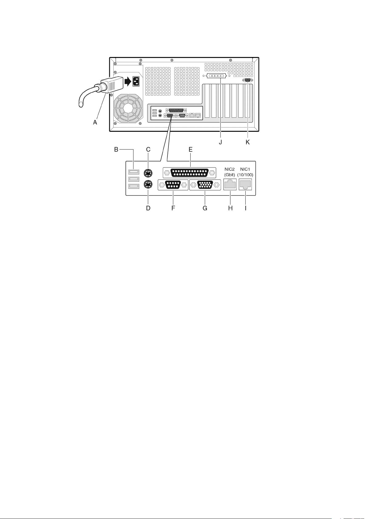
Figure 1. Back Panel Connectors
A.
AC Power*
B.
USB 1, 2, 3
C.
Mouse
D.
Keyboard
E.
Parallel Port
F.
Serial A
* Item may be different on your chassis.
G.
Video
H.
NIC2 (Gbit)
I.
NIC1 (10/100)
J.
ICMB/External SCSI Connector Knockout*
K.
Serial B Knockout*
Processor
The MAXDATA PLATINUM 5200 server mainboard supports one or two Intel® Xeon™
processors from 1.8 GHz to 2.4 GHz, with 512 KB of L2 advanced transfer cache packaged in
a 603-pin micro-PGA (Pin-Grid Array).
When two processors are installed, both processors must be identical. When only one
processor is installed, the processor must be installed in the CPU1 socket, which is the
socket closest to the corner of the server board.
Hyper-Threading Technology
The server supports Intel® Hyper-Threading technology. Hyper-Threading enabled processors appear to the operating system, if it supports this technology, as two separate
processors. In enterprise computing terms this means that on compatible applications,
this new technology has been demonstrated to provide server customers a performance
boost. This technology is enabled on MAXDATA PLATINUM 5200 Server as default. The
customer can enable/disable this feature in the BIOS Setup in the section Main > Processor
Settings > HyperThreading Technology >Enable/Disable .
8 Description
Page 9

Memory
The MAXDATA PLATINUM 5200 server mainboard contains six 184-pin DIMM sockets.
Memory is partitioned as three banks. DIMMs must be populated in identical pairs.
The MAXDATA PLATINUM 5200 server board supports up to six 2.5 V, ECC, DDR 200 or
266-compliant, registered SDRAM 184-pin gold DIMMs. A wide range of DIMM sizes are
supported, including 128 MB, 256 MB, 512 MB, 1 GB, and 2 GB DIMMs. The minimum
supported memory configuration is 256 MB, using two identical 128 MB DIMMs. The
maximum configurable memory size is 12 GB using six 2 GB DIMMs.
The SDRAM interface runs at a frequency of 200 MHz; however 266 MHz memory can
be used. The memory controller supports 2-way interleaved SDRAM, memory scrubbing,
single-bit error correction and multiple-bit error detection with Chipkill capability that allows
the system to continue to run even in the event of a multi-bit SDRAM failure.
Run even in the event of a multi-bit SDRAM failure. Memory can be implemented with either
single-sided (one row) or double-sided (two row) DIMMs.
Add-in Board Connectors
The server board has the following add-in board connectors:
• Two 184-pin full-length, 3.3 V, PCI--X 64-bit/100 MHz connectors.
• Three 120-pin full-length, 5 V, standard PCI 32-bit/33 MHz connectors.
• One 184-pin full-length, 3.3 V, connector that is capable if PCI--X 64-bit/133 MHz
operation.
To enable PCI--X 64-bit/133 MHz operation, you must disable the onboard SCSI controller
using BIOS Setup. The default operation of this connector (slot 6) is PCI 64-bit/66 MHz
operation.
Video
The system has an integrated ATI Rage XL 32-bit high-performance SVGA subsystem that
supports the following:
• BIOS compatibility with all standard VGA modes
• 8 MB of video memory
• Pixel resolutions up to 1600 x 1200 pixels per inch (ppi) in 8/16/24/32 bpp modes under
2D and up to 1024 x 768 ppi in 8/16/24/32 bpp modes under 3D
• Both CRT and LCD monitors up to 100 Hz vertical refresh rate
9MAXDATA PLATINUM 5200 Server Mainboard
Page 10

11MAXDATA PLATINUM 5200 Server Mainboard
Table 2. Video Modes
MAXDATA PLATINUM 5200 2D Mode Video Support
2D Mode Refresh Rate (Hz)
640x480 60, 72, 75, 90, 100 Supported Supported Supported Supported
800x600 60, 70, 75, 90, 100 Supported Supported Supported Supported
1024x768 60, 72, 75, 90, 100 Supported Supported Supported Supported
1280x1024 43, 60 Supported Supported Supported Supported
1280x1024 70, 72 Supported – Supported Supported
1600x1200 60, 66 Supported Supported Supported Supported
1600x1200 76, 85 Supported Supported Supported –
3D Mode Refresh Rate (Hz) MAXDATA PLATINUM 5200 3D Mode Video Support with Z
640x480 60, 72, 75, 90, 100 Supported Supported Supported Supported
800x600 60, 70, 75, 90, 100 Supported Supported Supported Supported
1024x768 60, 72, 75, 90, 100 Supported Supported Supported Supported
1280x1024 43, 60, 70, 72 Supported Supported – –
1600x1200 60, 66, 76, 85 Supported – – –
3D Mode Refresh Rate (Hz) MAXDATA PLATINUM 5200 3D Mode Video Support with Z
640x480 60, 72, 75, 90, 100 Supported Supported Supported Supported
800x600 60, 70, 75, 90, 100 Supported Supported Supported Supported
1024x768 60, 72, 75, 90, 100 Supported Supported Supported Supported
1280x1024 43, 60, 70, 72 Supported Supported Supported –
1600x1200 60, 66, 76, 85 Supported Supported – –
8 bpp 16 bpp 24 bpp 32 bpp
Buffer Enabled
Buffer Disabled
SCSI Controller
The embedded Adaptec AIC-7899W dual function SCSI controller provides Ultra160 (LVDS),
(Ultra 2), and Ultra wide (SE) SCSI interfaces as two independent PCI functions.
The MAXDATA PLATINUM 5200 server mainboard provides active terminators, termination
voltage, resetable fuse, and protection diode for both SCSI channels.
Modular RAID Capable PCI--X Slot 6
The MAXDATA PLATINUM 5200 server board supports a modular RAID controller, such
as the Intel® RAID Controller SRCMR, on PCI--X Slot 6. An add-in card installed in this slot
leverages the onboard SCSI controller along with its own built-in intelligence to provide a
complete RAID controller subsystem onboard. If a specified modular RAID card is installed,
then SCSI interrupts are routed to the RAID card instead of the PCI--X interrupt controller
effectively hiding the host-based I/O device from the system. The MAXDATA PLATINUM
5200 Server Board uses an implementation commonly referred to as “RAIDIOS” to support
this feature.
10 Description
Page 11

IDE Controller
The system includes a dual-channel enhanced IDE 32-bit interface controller for intelligent
disk drives with disk controller electronics onboard. The controller has two connectors,
Primary and Secondary, located on the system board, each of which supports a master and
a slave device. The device supports:
• PIO, ATA-100 Synchronous DMA, and bus master IDE transfer modes
• Ultra DMA 33/66/100 synchronous DMA transfers
• Master/slave IDE modes
• Up to four devices
USB Interface
The MAXDATA PLATINUM 5200 Server Board provides three external USB connectors on
the rear I/O panel. The external connectors are defined by the USB Specification, Revision
1.1. One additional USB connector is supported internally through a 10-pin header on the
server board that can be cabled to a front panel board. All four ports function identically and
with the same bandwidth.
Network Controllers
The server board includes two integrated onboard Network Interface Controllers (NICs). One
NIC is a 10BASE-T/100BASE-TX network solution based on the Intel® 82550PM single-chip Fast
Ethernet PCI Bus Controller. As a PCI bus master, the controller can burst data at up to 132 MB/s.
The controller contains two receive and transmit FIFO buffers that prevent data overruns or
underruns while waiting for access to the PCI bus. The controller has the following:
• 32-bit PCI bus master interface (direct drive of bus), compatible with PCI Bus Specification,
Revision 2.2
• Chained memory structure with improved dynamic transmit chaining for enhanced per formance
• Programmable transmit threshold for improved bus utilization
• Early receive interrupt for concurrent processing of receive data
• On-chip counters for network management
• Auto-detect and auto-switching for 10 or 100 Mbps network speeds
• Support for both 10 Mbps and 100 Mbps networks, capable of full or half duplex, with
back-to-back transmit at 100 Mbps
• Low-power +3.3 V device
• Alert on LAN functionality
The second NIC is an Intel® 82544GC Gigabit Ethernet Controller capable of providing 10/
100/1000 Mbps data rates. It is a single-chip device containing both the MAC and PHY layer
functions.
The 82544GC utilizes a 64-bit/100 MHz direct interface to the PCI--X bus. It is compliant
with the PCI Local Bus Specification, Revision 2.2. It also supports the PCI--X extension to
the PCI Local Bus, Revision 1.0a.
Note
If you install a 32/64-bit, 33/66 MHz PCI card in Add-in card slots 1 or 2, you will slow the
PCI--X bus to the speed of the card you install. This will also slow the 82455GC’s interface
to the PCI--X bus.
11MAXDATA PLATINUM 5200 Server Mainboard
Page 12

13MAXDATA PLATINUM 5200 Server Mainboard
Network Teaming Features
The network controller provides several options for increasing throughput and fault tolerance
when running Windows 2000 or NetWare 6.0 or newer:
• Adapter Fault Tolerance (AFT) - provides automatic redundancy for your adapter. If
the primary adapter fails, the secondary takes over. AFT works with any hub or switch.
• Adaptive Load Balancing (ALB) - creates a team of 2 - 4 adapters to increase transmission
throughput. Also includes AFT. Works with any 10Base-TX or 100Base-TX switch.
• Fast EtherChannel (FEC) - creates a team of 2, 3, or 4 adapters to increase transmission
and reception throughput. Also includes AFT. Requires an FEC-enabled switch.
Adapter Fault Tolerance
Adapter Fault Tolerance (AFT) is a simple, effective, and fail-safe approach to increase the
reliability of server connections. AFT gives you the ability to set up link recovery to the server
adapter in case of a cable, port, or network interface card failure. By assigning two server
adapters as a team, AFT enables you to maintain uninterrupted network performance.
AFT is implemented with two server adapters: a primary adapter and a backup, or secondary,
adapter. During normal operation, the backup will have transmit disabled. If the link to the
primary adapter fails, the link to the backup adapter automatically takes over.
Preferred Primary Adapter
With multiple adapters installed, you can specify one as the Preferred Primary adapter.
For example if you have a server with an Intel PRO/100 Intelligent Server adapter as the
primary adapter and an Intel PRO/1000 adapter as the secondary, you would want the
PRO/100 Intelligent Server adapter to be the preferred primary. In this scenario, if the PRO/
100 Intelligent Server adapter fails, the PRO/1000 will take over. Then when the PRO/100
Intelligent Server adapter is replaced, it will automatically revert to being the primary adapter
in the team.
If a Preferred Primary is not selected, the Intel PROSet II will attempt to select the best
adapter based on adapter model and speed.
Mixed Adapter Teaming
AFT supports up to four PRO/1000 or PRO/100 adapters per team, in any mix.
Adaptive Load Balancing
Adaptive Load Balancing (ALB) is a simple and efcient way to increase your server’s transmit
throughput. With ALB you group server adapters in teams to provide an increased transmit
rate (up to 400 Mbps) using a maximum of four adapters. The ALB software continuously
analyzes transmit loading on each adapter and balances the rate across the adapters as
needed. Adapter teams congured for ALB also provide the benets of AFT. Receive rates
remain at 100 Mbps.
To use ALB, you must have two, three, or four server adapters installed in your server or
workstation and linked to the same network switch.
Keyboard and Mouse
The keyboard/mouse controller is PS/2-compatible. If specied through the System Setup
Utility (SSU), tthe he server may be locked automatically if there is no keyboard or mouse
activity for a predened length of time. Once the inactivity (lockout) timer has expired, the
keyboard and mouse do not respond until the previously stored password is entered.
12 Description
Page 13

ACPI
The MAXDATA PLATINUM 5200 supports the Advanced Configuration and Power Interface
(ACPI) as defined by the ACPI 1.0b. An ACPI-aware operating system can put the system into
a sleep state where the hard drives spin down, the system fans stop, and all processing is
halted. However, the power supply will still be on and the processors will still be dissipating
some power, so the power supply fan and processor fans will still run.
The MAXDATA PLATINUM 5200 supports sleep states s0, s1, s4, and s5.
• s0: Normal running state.
• s1: Processor sleep state: No context will be lost in this state and the processor caches
will maintain coherency.
• s4: Hibernate or Save to Disk: The memory and machine state are saved to disk. Pressing
the power button or other wakeup event will restore the system state from the disk
and resume normal operation. This assumes that no hardware changes have been made
to the system while it was off.
• s5: Soft off: Only the real time clock (RTC) section of the chipset and the Baseboard
Management Controller (BMC) are running in this state.
CAUTION
The system is off only when the AC power is disconnected.
Security
To help prevent unauthorized entry or use of the server, the Server Management software
monitors the (optional) system intrusion switch.
Security with Mechanical Locks and Monitoring
If installed, you can activate the chassis intrusion alarm switch. When the side door is opened,
the switch transmits an alarm signal to the server board, where BMC rmware and server
management software process the signal. The system can be programmed to respond to
an intrusion by locking the keyboard, for example.
Software Locks
The BIOS Setup and the System Setup Utility (SSU) provide a number of security features
to prevent unauthorized or accidental access to the system. Once the security measures
are enabled, you can access the system only after you enter the correct password(s). For
example:
• Enable the keyboard lockout timer so that the server requires a password to reactivate
the keyboard and mouse after a specified time-out period - 1 to 120 minutes.
• Set and enable a supervisor password.
• Set and enable a user password.
• Set secure mode to prevent keyboard or mouse input and to prevent use of the front
panel reset and power switches.
• Activate a hot-key combination to enter secure mode quickly.
• Disable writing to the diskette drive when secure mode is set.
• Disable access to the boot sector of the operating system hard disk drive.
13MAXDATA PLATINUM 5200 Server Mainboard
Page 14

15MAXDATA PLATINUM 5200 Server Mainboard
Using Passwords
You can set either the user password, the supervisor password, or both passwords. If only
the user password is set, you:
• Must enter the user password to enter BIOS Setup or the SSU.
• Must enter the user password to boot the server if Password on Boot is enabled in
either the BIOS Setup or SSU.
• Must enter the user password to exit secure mode.
If only the supervisor password is set, you:
• Must enter the supervisor password to enter BIOS Setup or the SSU.
• Must enter the supervisor password to boot the server if Password on Boot is enabled
in either the BIOS Setup or SSU.
• Must enter the supervisor password to exit secure mode.
If both passwords are set, you:
• May enter the user password to enter BIOS Setup or the SSU. However, you will not
be able to change many of the options.
• Must enter the supervisor password if you want to enter BIOS Setup or the SSU and
have access to all of the options.
• May enter either password to boot the server if Password on Boot is enabled in either
the BIOS Setup or SSU.
• May enter either password to exit secure mode.
Secure Mode
Congure and enable the secure boot mode by using the SSU. When secure mode is in
effect:
• You can boot the server and the operating system will run, but you must enter the user
password to use the keyboard or mouse.
• You cannot turn off system power or reset the server from the front panel switches.
Secure mode has no effect on functions enabled via the Server Manager Module or power
control via the real time clock.
Taking the server out of secure mode does not change the state of system power. That is,
if you press and release the power switch while secure mode is in effect, the system will not
be powered off when secure mode is later removed. However, if the front panel power
switch remains depressed when secure mode is removed, the server will be powered off.
14 Description
Page 15

Summary of Software Security Features
The table below lists the software security features and describes what protection each
offers. In general, to enable or set the features listed here, you must run the SSU and go
to the Security Subsystem Group, menu. The table also refers to other SSU menus and to
the BIOS Setup utility.
Table 3. Software Security Features
Feature Description
Secure mode How to enter secure mode:
• Setting and enabling passwords automatically places the system in secure
mode.
• If you set a hot-key combination (through Setup), you can secure the
system simply by pressing the key combination. This means you do not
have to wait for the inactivity time-out period.
When the system is in secure mode:
The server can boot and run the operating system, but mouse and keyboard
input is not accepted until the user password is entered.
At boot time, if a CD is detected in the CD-ROM drive or a diskette in drive
A, the system prompts for a password. When the password is entered, the
server boots from CD or diskette and disables the secure mode.
If there is no CD in the CD-ROM drive or diskette in drive A, the server boots
from drive C and automatically goes into secure mode. All enabled secure
mode features go into effect at boot time.
To leave secure mode: Enter the correct password(s).
Disable writing to diskette In secure mode, the server will not boot from or write to a diskette unless a
password is entered.
To write protect access to diskette whether the server is in secure mode or
not, use the Setup main menu, Floppy Options, and specify Floppy Access as
read only.
Set a time-out period so
that keyboard and mouse
input are not accepted
Also, screen can be blanked, and writes to diskette can be inhibited
Control access to using
the SSU: set supervisor
password
Control access to the
system other than SSU:
set user password
Boot without keyboard The system can boot with or without a keyboard. During POST, before the
Specify and enable an inactivity time-out period of from 1 to 120 minutes.
If no keyboard or mouse action occurs for the specified period, attempted
keyboard and mouse input will not be accepted.
The monitor display will go blank, and the diskette drive will be write protected (if these security features are enabled through Setup).
To resume activity: Enter the correct password(s).
To control access to setting or changing the system configuration, set a su-
pervisor password and enable it through Setup.
If both the supervisor and user passwords are enabled, either can be used to
boot the server or enable the keyboard and/or mouse, but only the supervisor
password will allow Setup to be changed.
To disable a password, change it to a blank entry or press CTRL-D in the
Change Password menu of the Supervisor Password Option menu found in
the Security Subsystem Group.
To clear the password if you cannot access Setup, change the Clear Password jumper.
To control access to using the system, set a user password and enable it
through Setup.
To disable a password, change it to a blank entry or press CTRL-D in the
Change Password menu of the User Password Option menu found in the
Security Subsystem Group.
To clear the password if you cannot access Setup, change the Clear Password jumper.
system completes the boot sequence, the BIOS automatically detects and
tests the keyboard if it is present and displays a message.
15MAXDATA PLATINUM 5200 Server Mainboard
Page 16

16 Description 17MAXDATA PLATINUM 5200 Server Mainboard
Page 17

2 Upgrading
Installing Memory
The MAXDATA PLATINUM 5200 Server Board contains six 184-pin DIMM sockets. Memory
is partitioned as three banks. DIMMs must be populated in identical pairs.
Figure 2. DIMM Locations
The MAXDATA PLATINUM 5200 server board supports up to six 2.5 V, ECC, DDR 200 or
266-compliant, registered SDRAM 184-pin gold DIMMs. A wide range of DIMM sizes are
supported, including 128 MB, 256 MB, 512 MB, 1 GB, and 2 GB DIMMs. The minimum
supported memory configuration is 256 MB, using two identical 128 MB DIMMs. The
maximum configurable memory size is 12 GB using six 2 GB DIMMs.
The SDRAM interface runs at 200 MHz; however 266 MHz memory can be used. The
memory controller supports 2-way interleaved SDRAM, memory scrubbing, single-bit error
correction and multiple-bit error detection with Chipkill capability that allows the system to
continue to run even in the event of a multi-bit SDRAM failure. Memory can be implemented
with either single-sided (one row) or double-sided (two row) DIMMs.
Page 18

1. If the server board is not already installed in the chassis, remove the server board from it’s
packaging and place it on a clean ESD protected work surface such as the antistatic plastic
packaging in which the board was shipped.
2. Open both DIMM socket levers.
3. Insert DIMM making sure the connector edge of the DIMM aligns correctly with the
slot.
4. Check that socket levers are securely latched. DIMMs must be populated in identical
pairs.
Figure 3. Installing Memory
18 Upgrading 19MAXDATA PLATINUM 5200 Server Mainboard
Page 19

3 Configuration Software and Utilities
This chapter describes the Power-On Self-Test (POST) and server conguration utilities. The
table below briey describes the utilities.
Table 4. Conguration Utilities
Utility Description
BIOS Setup Used for modifying server board set features, including setting time, date, and
system passwords; setting the boot device priority; configuring the diskette
drive and serial ports; and enabling the SCSI BIOS and system management
features.
System Setup Utility
(SSU)
FRUSDR Load Utility Used for updating the Field Replacement Unit (FRU), Sensor Data Record (SDR),
BIOS Upgrade Utility Used to upgrade the BIOS.
Firmware Update Utility Used to update the Firmware.
Adaptec SCSI Utility Used to configure or view the settings of the SCSI host adapters and onboard
Used for viewing and clearing the system event log, viewing the system management FRU information, or viewing the system management SDR repository.
and SM BIOS (SMB) flash components.
SCSI devices in the server.
Hot Keys
Use the keyboard’s numeric pad to enter numbers and symbols.
Table 5. Hot Keys
To do this: Press these keys
Clear memory and reload the operating
system - this is a system reset.
Secure your system immediately. <Ctrl+Alt>+hot key (Set your hot key combination with Setup.)
<Ctrl+Alt+Del>
Power-On Self-Test (POST)
Each time you turn on the system, POST starts running. POST checks the server board,
processor, memory, keyboard, and most installed peripheral devices. During the memory
test, POST displays the amount of memory that it is able to access and test. The length of
time needed to test memory depends on the amount of memory installed. POST is stored
in flash memory.
1. Turn on your video monitor and server. After a few seconds POST begins to run.
2. After the memory test, these screen prompts and messages appear:
Press <F2> to enter SETUP
3. If you do not press <F2> and do NOT have a device with an operating system loaded,
the above message remains for a few seconds while the boot process continues, and
the system beeps once. Then this message appears:
Operating system not found
If you do not press <F2> and DO have an operating system loaded, the boot process
continues, and this message appears:
Press <Ctrl><A> to enter SCSI Utility
4. Press <Ctrl+A> if there are SCSI devices installed. When the utility opens, follow the
displayed instructions to configure the onboard SCSI host adapter settings and to run
the SCSI utilities. Also see “Using the Adaptec SCSI Utility”. If you do not enter the SCSI
utility, the boot process continues.
5. Press <Esc> during POST to pop up a boot menu when POST nishes. From this menu
you can choose the boot device or enter BIOS Setup.
Page 20

21MAXDATA PLATINUM 5200 Server Mainboard
After POST completes, the system beeps once.
What appears on the screen after this depends on whether you have an operating system
loaded and if so, which one.
If the system halts before POST completes running, it emits a beep code indicating a fatal
system error that requires immediate attention. If POST can display a message on the video
display screen, it causes the speaker to beep twice as the message appears.
Note the screen display and write down the beep code you hear; this information is useful
for your service representative. For a listing of beep codes and error messages that POST
can generate, see the “Monitoring POST”.
Using BIOS Setup
This section describes the BIOS Setup options. Use Setup to change the server conguration
defaults. You can run Setup with or without an operating system being present. Setup stores
most of the conguration values in battery backed CMOS; the rest of the values are stored in
ash memory. The values take effect when you boot the server. POST uses these values to
congure the hardware; if the values and the actual hardware do not agree, POST generates
an error message. You must then run Setup to specify the correct conguration.
Record Your Setup Settings
Record your setup settings on a worksheet. If the default values ever need to be restored
(after a CMOS clear, for example), you must run Setup again. Referring to the worksheet
could make your task easier.
If You Cannot Access Setup
If the diskette drive is miscongured so that you cannot access it to run a utility from a
diskette, you may need to clear CMOS memory. You will need to open the server, change
a jumper setting, use Setup to check and set diskette drive options, and change the jumper
back. For a step-by-step procedure, see the heading “CMOS Jumper.”
Starting Setup
You can enter and start Setup under several conditions:
• When you turn on the server, after POST completes the memory test.
• When you reboot the server by pressing <Ctrl+Alt+Del> while at the DOS operating
system prompt.
• When you have moved the CMOS jumper on the server board to the “Clear CMOS”
position (enabled); for the procedure, see “Server Board Jumpers”.
In the three conditions listed above, after rebooting, you will see this prompt:
Press <F2> to enter SETUP
NOTE
If the BIOS setup option “POST Diagnostic Screen” is enabled (Default), you will not see the
message “Press <F2> to enter SETUP.” This message is hidden by the Manufacturer’s Splash
screen. To see the message, press the <ESC> key while the splash screen is displayed.
This will temporarily disable the splash screen allowing you to see the message.
In a fourth condition, when CMOS/NVRAM has been corrupted, you will see other prompts
but not the <F2> prompt:
Warning: cmos checksum invalid
Warning: cmos time and date not set
In this condition, the BIOS will load default values for CMOS and attempt to boot.
20 Configuration Software and Utilities
Page 21

Using the System Setup Utility
The System Setup Utility (SSU) is located on the Server Board Resource CD-ROM shipped
with the server.
Run the System Setup Utility to:
• Set boot device priority
• Set passwords and security options
• View system events
• View FRU information
• View sensor data records
• Update system firmware and BIOS
• Save and restore the system configuration
• Set up the server to send alerts for platform events
• Set up the server for remote management
You can specify the boot device sequence and set up system passwords and security options.
Both utilities access the same stored configuration data for these items, and the result of
making a change to these settings using either utility is identical.
The SSU consists of a collection of task-oriented modules plugged into a common framework
called the Application Framework (AF). The Application Framework provides a launching point
for individual tasks and a location for setting customization information.
Creating SSU Diskettes
You can run the SSU directly from the Utilities menu of the System Resource CD-ROM,
from a set of DOS diskettes, or from the service partition of the hard disk.
If you choose to run the SSU from a set of DOS diskettes, you must create the SSU diskettes
from the Resource CD-ROM as follows:
1. Boot to the System Resource CD-ROM.
2. Choose Create Diskettes > Create Diskettes by Device/Function > System Setup
Utility.
3. Follow the instructions displayed.
Alternatively, if you have a workstation with the Microsoft® Windows® operating system,
you can insert the CD into that system and create the diskettes on that system.
Running the SSU
When the SSU starts in the default local execution mode, the SSU accepts input from the
keyboard or mouse. The SSU presents a VGA-based GUI on the primary monitor.
If you run the SSU from read-only media, such as the CD-ROM, you cannot save user
preference settings (such as screen colors).
The SSU supports ROM-DOS version 6.22. The SSU will not operate from a “DOS box”
running under an operating system such as Windows®.
To start the SSU:
1. Start the SSU using one of the following methods:
– From diskettes: Insert the first SSU diskette in drive A and boot the server from the
diskette. You are prompted to insert the second diskette. After loading completes the
SSU starts automatically.
21MAXDATA PLATINUM 5200 Server Mainboard
Page 22

23MAXDATA PLATINUM 5200 Server Mainboard
– From the System Resource or ISM CD-ROM: Boot the server to the System Resource
CD and start the SSU from the Utilities menu.
– From the Service Partition: Boot the server to the Service Partition and execute the
following DOS commands:
C:\> cd ssu
C:\SSU> ssu.bat
2. The mouse driver loads if it is available; press Enter to continue.
3. When the SSU title appears on the screen, press Enter to continue.
Working with the GUI
You can access features of the GUI using the mouse or keyboard:
• Mouse – Click once to choose menu items and buttons or to select items in a list, such as
the Available Tasks list. To run a list item, such as one of from the Available Tasks list, select
the item and click OK or double-click the item.
• Keyboard – Use the tab and arrow keys to highlight buttons and press the spacebar
or <Enter> to execute. You can also execute a menu or button by using the <Alt> key in
combination with the underlined letter in the name of the menu or button.
You can have more than one task open at the same time, although some tasks might require
complete control to avoid possible conflicts. The tasks achieve complete control by keeping
the task as the center of operation until you close the task window.
The SSU has a build-in help system, which you access by clicking a Help button or choosing
the Help menu.
Customizing the SSU Interface
The SSU lets you customize your interface using the Preferences section of the main window.
The SSU sets these preferences and saves them in the AF.INI file so that they take effect
the next time you start the SSU. There are four user customizable settings:
• Color – lets you change the default colors associated with different items on the
screen using predefined color combinations. The color changes take effect immedi ately.
• Mode – lets you set the desired expertise level: novice, intermediate, or expert.
The expertise level determines which tasks are visible in the Available Tasks section and
which actions each task performs. For a new mode setting to take effect, you must exit the
SSU and restart it.
• Language - lets you change the text in the SSU to the appropriate language. For a new
language setting to take effect, you must exit the SSU and restart it.
• Other - lets you show or hide the status bar at the bottom of the SSU main window.
The change takes effect immediately.
NOTE
If you run the SSU from read-only media (CD-ROM, for example), these preferences are lost
when you exit the SSU.
Exiting the SSU
Exiting the SSU closes all SSU windows.
22 Configuration Software and Utilities
Page 23

Setting Boot Device Priority
To change the boot priority of a device:
1. From the SSU Main window, choose Boot Devices.
2. In the Multiboot Options Add-in window, select a device.
3. Click the Move Up button to move it up in the list. Click the Move Down button to move
it down.
Setting Passwords and Security Options
You can set a user password and an admin password. On some systems, you must set an
admin password before you can set a user password. On other systems, the passwords are
independent. You can set the same passwords and security options by using BIOS Setup.
Setting the Admin Password
The Admin Password button lets you set or change the admin password used by both the
SSU and the system BIOS. This option is not available if both an admin and a user password
are set and you entered only the user password when you started the SSU. All changes to
the admin password take effect immediately.
To change or clear the administrator password:
1. From the SSU Main window, choose Security.
2. Click the Admin Password button.
3. If you are changing passwords, enter the old password.
4. Enter the new password (or leave blank to clear).
5. Confirm the password by entering it again (or leave blank to clear).
6. Click OK to save the password and return to the Security window.
Setting the User Password
The User Password button lets you set or change the user password used by both the SSU
and the system BIOS. All changes to the user password take effect immediately.
To change or clear the user password:
1. From the SSU Main window, choose Security.
2. Click the User Password button.
3. If you are changing passwords, enter the old password in the first box.
4. Enter the new password (or leave blank to clear).
5. Confirm the password by entering it again (or leave blank to clear).
6. Click OK to save the password and return to the Security window.
23MAXDATA PLATINUM 5200 Server Mainboard
Page 24

25MAXDATA PLATINUM 5200 Server Mainboard
Setting Security Options
To set the security options:
1. In the Security window, click the Options button.
2. For each option, select the desired setting from the list. The options are:
• Security Hot Key: The key combination that can be used to put the server into secure
mode.
• Secure Mode Timer: If no keyboard or mouse activity occurs during the chosen
time interval, the server enters secure mode.
• Secure Mode Boot: Enable forces the server to boot directly into secure mode.
• Video Blanking: Enable turns off the video when the server is in secure mode.
• Floppy Write: Enable prevents writing to the diskette drive while the server is in
secure mode.
• Power Switch Inhibit: Enable prevents the power and reset buttons from functioning
when the server is in secure mode. Disable allows the power and reset buttons to
function normally when the server is in secure mode.
3. Click Save to save the settings and return to the Security window.
Viewing the System Event Log
To view the System Event Log (SEL):
1. From the SSU Main window, choose SEL Manager.
When you start the SEL Manager, it automatically loads the current list of events from
non-volatile memory.
2. Use the <F4> and <F5> keys to scroll the window contents to the left and right to view
all of the columns.
3. Use the File and SEL menu items to work with the SEL information:
• Open: Views data from a previously saved SEL file.
• Save As: Saves the currently loaded SEL data to a file.
• Properties: Displays information about the SEL.
• Clear SEL: Clears the SEL data from the nonvolatile storage area.
• Reload: Refreshes the display by reading the current SEL entries from the server.
• Sort By: Sorts the displayed events by event number, time stamp, sensor type and
number, event description, or event generator ID.
24 Configuration Software and Utilities
Page 25

Viewing FRU Information
To view the Field Replaceable Unit (FRU) information:
1. From the SSU Main window, choose FRU Manager.
When you start the FRU Manager, it automatically loads the current list of events from nonvolatile memory.
The FRU Manager window has a navigation pane on the left that displays, in a tree format,
the inventory of components in the server. The tree has three categories: Chassis, Board, and
Product. Clicking on a category expands or collapses a list of components for that category.
Clicking on an individual component displays the FRU information for that component in
the presentation pane in the upper right. The description pane in the lower right displays a
description of the currently selected FRU area.
2. Use the <F4> and <F5> keys to scroll the window contents to the left and right to view
all of the columns.
3. Use the File and FRU menu items to work with the FRU information:
• Open: Views data from a previously saved FRU file.
• Save As: Saves the currently loaded FRU data to a file.
• Properties: Displays the number of FRU devices in the system and the number being
displayed. Only FRU devices with valid FRU areas are displayed.
• Reload: Refreshes the display by reading the current FRU entries from the server.
Viewing Sensor Data Records
To view the Sensor Data Records (SDR):
1. From the SSU Main window, choose SDR Manager.
When you start the SDR Manager, it automatically loads the SDR entries from non-volatile
memory.
The SDR Manager window has a navigation pane on the left that displays, in a tree format,
the sensor data records. The tree has categories for each type of record. Clicking on a
category expands or collapses a list of SDRs for that category. Clicking on an individual
SDR displays the information for that SDR in the presentation pane in the upper right.
The description pane in the lower right displays a description of the currently selected
SDR type.
2. Use the <F4> and <F5> keys to scroll the window contents to the left and right to view
all of the columns.
3. Use the File and SDR menu items to work with the SDR information:
• Open: Views data from a previously saved SDR file.
• Save As: Saves the currently loaded SDR data to a file.
• Properties: Displays information about the SDR, including IPMI version, number of
SDR entries, time stamps for changes to the SDR information, and free space
remaining.
• Reload: Refreshes the display by reading the SDR data from the server.
25MAXDATA PLATINUM 5200 Server Mainboard
Page 26

27MAXDATA PLATINUM 5200 Server Mainboard
Saving and Restoring the System Configuration
Using the SSU, you can save the following configuration information to a file:
• Platform type, BIOS revision, and firmware revision
• CMOS settings
• Extended system configuration data (ESCD)
• Settings for the emergency management port (EMP), platform event paging (PEP), and
BMC LAN alerts
Data is saved from all sources. There is no way to choose only certain pieces of configuration
data to save. You can also restore the information from a saved configuration file.
NOTE
BIOS passwords are stored in the file. Restoring a configuration can change passwords on
a server. EMP and LAN passwords are not stored in the file.
Saving a Configuration
To save the system configuration:
1. From the SSU Main window, choose Config Save/Restore. (Configuration Save/Restore
is available only in Expert mode.)
2. Click Save To File and specify a filename and location.
Restoring a Configuration
To restore the system configuration from a file:
1. From the SSU Main window, choose Config Save/Restore. (Configuration Save/Restore
is available only in Expert mode.)
2. Click Restore from File and specify a filename and location.
The CSR reads the platform type, BIOS revision, and firmware revision from the file and
compares that information with the same information retrieved from the server. If the two
do not match, an error message is displayed and the restore operation aborts. If they do
match, the CSR restores the configuration data to the server. It prompts you to reboot the
server for the new settings to take effect.
Alerting for Platform Events
You can set up the server to alert you when various events occur. Alerts can be delivered
either as telephone pages, over the LAN, or by email.
Setting Up Email Alerts
You can receive email alerts for any of the same events supported by LAN alert or Platform
Events Paging. Unlike LAN Alert and Platform Events Paging that can be configured using
the SSU, you must use the Server Management Platform Interface Control (PIC) software
to configure an email address to receive alerts.
Setting Up Paging Alerts
To set up the server to send alerts as telephone pages:
1. Install an external modem on the Emergency Management Port (COM2).
26 Configuration Software and Utilities
Page 27

2. From the SSU Main window, choose Platform Event Manager (PEM).
3. In the PEM window, click Configure EMP.
4. In the corresponding boxes, enter the following command strings for the modem
attached to the EMP port:
• ESC Sequence: the escape sequence. This string is sent to the modem before
sending command strings. The maximum string length for the string is five charac ters; longer strings are truncated.
• Hangup String: hang up or drop the connection. The EMP automatically sends
an <ENTER> character following this string. The maximum string length for the
string is eight characters; longer strings are truncated.
• Modem Dial Command: the command to dial a phone number. This string is sent to
the modem before sending the paging string.
• Modem Init String: the initialization string for the modem. This string is sent every
time the EMP initializes. The maximum length for the string is determined at run
time from firmware. You will be notified if the string is truncated. Following a save,
the actual string saved is displayed in the edit box.
5. Click Save to save the changes.
6. Click Close to return to the PEM window.
7. In the PEM window, click Configure PEP.
8. Select the Enable PEP check box.
9. In the Blackout Period box, enter the minimum time, in minutes, between successive
pages. The valid range is [0 - 255] where 0 disables the blackout period. Setting a blackout
period can save you from being flooded with repeat pages. After you receive a PEP page,
no additional pages are sent by PEP for the duration of the blackout period.
10. In the Paging String box, enter the phone number to dial for the page and the message
you want sent with the page. The maximum length for the paging string is determined
at run time from firmware. You will be notified if the string is truncated. Following a save,
the actual string saved is displayed in the edit box.
11. From the Options menu, choose Configure Event Actions.
12. In the Platform Event Paging Actions window, move the events that you want to generate an
alert to the Enabled column and move all other events to the disabled column using
the following buttons:
>>: Moves all events from the enabled list to the disabled list.
>: Moves the selected event from the enabled list to the disabled list.
<: Moves the selected event from the disabled list to enabled the list.
<<: Moves all events from the disabled list to the enabled list.
13. Click Save to save the changes.
14. Click Close to return to the PEP Configuration window.
15. To send a test page to verify that you have correctly configured PEP, from the Options
menu, choose Send Alert.
16. Click Save to save the configuration.
17. Click Close to return to the Platform Event Manager window.
27MAXDATA PLATINUM 5200 Server Mainboard
Page 28

29MAXDATA PLATINUM 5200 Server Mainboard
Setting Up LAN Alerts
To set up the server to send alerts over the LAN:
1. Configure the remote system to receive alerts. For more information, see the documentation
for Server Management software.
2. From the SSU Main window, choose Platform Event Manager (PEM).
3. In the PEM window, click Configure LAN.
4. Select the Enable LAN Alerts check box.
5. (Optional) In the SNMP Community String box, enter a string for the community field in the
Header section of the SNMP trap sent for an alert. The string must be from 5 to 16
characters. The default string is public.
6. In the IP Setup box, choose either:
• DHCP: the IP address for the server is automatically assigned by the DHCP (dyna mic host control protocol) server on the network. The Host, Gateway, and Subnet Mask
boxes in the dialog are ignored.
• Static: assign the IP address for the server using the Host, Gateway, and Subnet Mask
boxes in the dialog.
7. If you chose Static IP Setup in the previous step, fill in the IP addressing boxes:
• Host IP Address: the IP address of this server.
• Gateway IP Address: the IP address of the router for this server.
• Subnet Mask: the IP address for the server’s subnet. The server uses this to decide
if the alert destination is on the same subnet.
8. In the Alert IP Address box, fill in the IP address of the system you want to receive alerts
from this server. If you want the alert to be broadcast to an entire subnet, enter the IP
address for the subnet.
9. From the Options menu, choose Configure Event Actions.
10. In the BMC LAN Alerting Actions window, move the events that you want to generate an
alert to the Enabled column and move all other events to the disabled column using the
following buttons:
>>: Moves all events from the enabled list to the disabled list.
>: Moves the selected event from the enabled list to the disabled list.
<: Moves the selected event from the disabled list to enabled the list.
<<: Moves all events from the disabled list to the enabled list.
11. Click Save to save the changes.
12. Click Close to return to the BMC LAN Configuration window.
13. To send a test alert to verify that you have correctly configured BMC LAN alerts, from
the Options menu, choose Send Alert.
14. Click Save to save the changes.
15. Click Close to return to the PEM window.
28 Configuration Software and Utilities
Page 29

Managing the Server Remotely
You can set up the server to so that you can connect to it from a remote client system to
perform management tasks. You can make the connection over a LAN or by using a modem
or direct serial cable to the Emergency Management Port (EMP). Instructions for setting up
the server for remote LAN and serial/modem access are given below.
Setting Up Remote LAN Access
To configure remote LAN access:
1. From the SSU Main window, choose Platform Event Manager (PEM).
2. In the PEM window, click Configure LAN.
3. If you want to require a password for remote access, enter the password in the Enter New
Password box and in the Verify New Password box. Passwords can be from 1 to 16
characters long, using any ASCII character in the range [32-126]. To clear the passwords,
leave both boxes blank. (You can also clear the password by choose the menu Options
Clear LAN Password.)
4. From the LAN Access Mode list, select the remote access mode:
• Full Access: a remote system can initiate a LAN connection regardless of the state
or health of the server.
• Restricted: a remote system can initiate a LAN connection, but cannot perform control
operations such as power down, reset, or front panel NMI.
• Disabled: remote systems are not allowed to initiate LAN connections.
5. In the IP Setup box, choose either:
• DHCP: the IP address for the server is automatically assigned by the DHCP
(dynamic host control protocol) server on the network. The Host, Gateway, and Sub net Mask boxes in the dialog are ignored.
• Static: assign the IP address for the server using the Host, Gateway, and Subnet Mask
boxes in the dialog.
6. If you chose Static IP Setup in the previous step, fill in the IP addressing boxes:
• Host IP Address: the IP address of this server.
• Gateway IP Address: the IP address of the router for this server.
• Subnet Mask: the IP address for the server’s subnet. The server uses this to decide
if the alert destination is on the same subnet.
7. Click Save to save the changes.
8. Click Close to return to the PEM window.
Setting Up Remote Modem or Serial Access
To configure remote modem or serial access:
1. From the SSU Main window, choose Platform Event Manager (PEM).
2. In the PEM window, click Configure EMP.
3. If you want to require a password for remote access, enter the password in the Enter New
Password box and in the Verify New Password box. Passwords can be from 1 to 16
characters long, using any ASCII character in the range [32-126]. To clear the passwords,
leave both boxes blank. (You can also clear the password by choose the menu Options >
Clear LAN Password.)
29MAXDATA PLATINUM 5200 Server Mainboard
Page 30

4. In the Modem Ring Time box, enter the number of 500ms intervals that the BMC
should wait before taking control of the COM2 port and answering an incoming call. A
value greater than zero gives the BIOS time to answer before the BMC takes control. A
value of zero causes the BMC to answer immediately. The maximum value, 63, tells
the BMC to ignore the call. Modem Ring Time applies only to Preboot access mode and
is ignored for other access modes.
5. In the System Phone Number box, enter the number for the phone line connected to
the modem on the EMP.
6. From the Access Mode list, choose the remote access mode:
• Always Active: the EMP is available at any time.
• Preboot: the EMP is available only when the server is powered down or is in the
running POST during startup.
• Disabled: remote systems are not allowed to initiate connections.
7. From the Restricted Mode list, choose either:
• Enabled: a remote system can initiate a connection, but cannot perform control
operations such as power down, reset, or front panel NMI.
• Disabled: the remote system has full control of the server.
8. From the Connection Mode list, choose either:
• Direct Connect: the COM2 port on the server is connected by a serial cable to the
remote system.
• Modem Connect: the COM2 port on the server is connected to a modem.
9. Click Save to save the changes.
10. Click Close to return to the PEM window.
Using the Adaptec SCSI Utility
The Adaptec SCSI utility detects the SCSI host adapters on the server board. The utility runs
out of BIOS and is used to:
• Change default values
• Check and/or change SCSI device settings that may conflict with those of other devices
in the server
Running the SCSI Utility
1. When this message appears on the video monitor:
Press Ctrl-A to run SCSI Utility...
2. Press <Ctrl+A> to run this utility. When it appears, choose the host adapter that you
want to configure.
30 Configuration Software and Utilities 31MAXDATA PLATINUM 5200 Server Mainboard
Page 31

4 Solving Problems
This chapter helps you identify and solve problems that might occur while you are using
the system.
Resetting the System
To do this: Press:
Soft boot reset, which clears system memory and reloads the operating system. <Ctrl+Alt+Del>
Clear system memory, restart POST, and reload the operating system. Reset button
Cold boot reset. Turn the system power off and then on. This clears system memory, restarts POST, reloads the operating system, and halts power to all peripherals.
Initial System Startup
Problems that occur at initial system startup are usually caused by incorrect installation or
conguration. Hardware failure is a less frequent cause.
Power off/on
Checklist
q Are the power supplies turned on? Check the switches on the back of the chassis.
q Are all cables correctly connected and secured?
q Are the processors fully seated in their slots on the server board?
q Are all add-in PCI boards fully seated in their slots on the server board?
q Are all jumper settings on the server board correct?
q Are all jumper and switch settings on add-in boards and peripheral devices correct? To check
these settings, refer to the manufacturer’s documentation that comes with them. If
applicable, ensure that there are no conicts – for example, two add-in boards sharing the
same interrupt.
q Are all DIMMs installed correctly?
q Are all peripheral devices installed correctly?
q If the system has a hard disk drive, is it properly formatted or congured?
q Are all device drivers properly installed?
q Are the conguration settings made in BIOS Setup correct?
q Is the operating system properly loaded? Refer to the operating system documentation.
q Did you press the system power on/off switch on the front panel to turn the server on
(power on light should be lit)?
q Is the system power cord properly connected to the system and plugged into a NEMA
5-15R outlet for 100-120 V∼ or a NEMA 6-15R outlet for 200-240 V∼?
q Is AC power available at the wall outlet?
Page 32

33MAXDATA PLATINUM 5200 Server Mainboard
Running New Application Software
Problems that occur when you run new application software are usually related to the
software. Faulty equipment is much less likely, especially if other software runs correctly.
Checklist
q Does the system meet the minimum hardware requirements for the software? See
the software documentation.
q Is the software an authorized copy? If not, get one; unauthorized copies often do not
work.
q If you are running the software from a diskette, is it a good copy?
q If you are running the software from a CD-ROM disk, is the disk scratched or dirty?
q If you are running the software from a hard disk drive, is the software correctly installed?
Were all necessary procedures followed and les installed?
q Are the correct device drivers installed?
q Is the software correctly congured for the system?
q Are you using the software correctly?
If the problems persist, contact the software vendor’s customer service representative.
After the System Has Been Running Correctly
Problems that occur after the system hardware and software have been running correctly
may indicate equipment failure. Many situations that are easy to correct, however, can also
cause such problems.
Checklist
q If you are running the software from a diskette, try a new copy of the software.
q If you are running the software from a CD-ROM disk, try a different disk to see if the
problem occurs on all disks.
q If you are running the software from a hard disk drive, try running it from a diskette. If the
software runs correctly, there may be a problem with the copy on the hard disk drive.
Reinstall the software on the hard disk, and try running it again. Make sure all necessary
les are installed.
q If the problems are intermittent, there may be a loose cable, dirt in the keyboard (if keyboard
input is incorrect), a marginal power supply, or other random component failures.
q If you suspect that a transient voltage spike, power outage, or brownout might have
occurred, reload the software and try running it again. (Symptoms of voltage spikes include
a ickering video display, unexpected system reboots, and the system not responding to
user commands.)
NOTE
Random errors in data files: If you are getting random errors in your data files, they may be
getting corrupted by voltage spikes on your power line. If you are experiencing any of the
above symptoms that might indicate voltage spikes on the power line, you may want to
install a surge suppressor between the power outlet and the system power cord.
32 Solving Problems
Page 33

More Problem Solving Procedures
This section provides a more detailed approach to identifying a problem and locating its
source.
Preparing the System for Diagnostic Testing
CAUTION
Turn off devices before disconnecting cables: Before disconnecting any peripheral cables
from the system, turn off the system and any external peripheral devices. Failure to do so
can cause permanent damage to the system and/or the peripheral devices.
1. Turn off the system and all external peripheral devices. Disconnect all of them from
the system, except the keyboard and video monitor.
2. Make sure the system power cord is plugged into a properly grounded AC outlet.
3. Make sure your video display monitor and keyboard are correctly connected to the
system. Turn on the video monitor. Set its brightness and contrast controls to at least
two thirds of their maximum ranges (see the documentation supplied with your video
display monitor).
4. If the operating system normally loads from the hard disk drive, make sure there is no
diskette in drive A. Otherwise, place a diskette containing the operating system files in
drive A.
5. Turn on the system. If the power LED does not light, see “Power Light Does Not
Light”.
Monitoring POST
The server may start to beep while booting. These beeps identify system events. The
following gives a description of possible beep codes.
Table 6. Beep Codes
Beep Code Description
1 One short beep before boot (this is normal, not an error)
1-2 Search for option ROMs. One long, two short beeps on checksum failure
1-2-2-3 BIOS ROM checksum
1-3-1-1 Test DRAM refresh
1-3-1-3 Test 8742 Keyboard Controller
1-3-3-1 Auto size DRAM, system BIOS stops execution here if the BIOS does not detect any usab-
le memory DIMMs
1-3-4-1 Base RAM failure; BIOS stops execution here if entire memory is bad
2-1-2-3 Check ROM copyright notice
2-2-3-1 Test for unexpected interrupts
Verifying Proper Operation of Key System Lights
As POST determines the system conguration, it tests for the presence of each mass storage
device installed in the system. As each device is checked, its activity light should turn on
briey. Check for the following:
q Does the diskette drive activity light turn on briey? If not, see “Diskette Drive Activity
Light Does Not Light”.
q If a second diskette drive is installed, does its activity light turn on briey? If not, see
“Diskette Drive Activity Light Does Not Light”.
33MAXDATA PLATINUM 5200 Server Mainboard
Page 34

35MAXDATA PLATINUM 5200 Server Mainboard
Conrming Loading of the Operating System
Once the system boots up, the operating system prompt appears on the screen. The prompt
varies according to the operating system. If the operating system prompt does not appear,
see “Initial System Startup”.
Specic Problems and Corrective Actions
This section provides possible solutions for these specific problems:
• Power light does not light
• There is no beep or an incorrect beep pattern
• No characters appear on screen
• Characters on the screen appear distorted or incorrect
• System cooling fans do not rotate
• Diskette drive activity light does not light
• CD-ROM drive activity light does not light
• There are problems with application software
• The bootable CD-ROM is not detected
Try the solutions in the order given. If you cannot correct the problem, contact your service
representative or authorized dealer for help.
Power Light Does Not Light
Check the following:
q Is the system operating normally? If so, the power LED may be defective or the cable
from the front panel to the server board is loose.
q Are there other problems with the system? If so, check the items listed under
“System Cooling Fans Do Not Rotate Properly.”
If all items are correct and problems persist, contact your service representative or authorized dealer for help.
No Characters Appear on Screen
Check the following:
q Is the keyboard functioning? Check to see that the “Num Lock” light is functioning.
q Is the video monitor plugged in and turned on?
q Are the brightness and contrast controls on the video monitor properly adjusted?
q Are the video monitor switch settings correct?
q Is the video monitor signal cable properly installed?
q Is the onboard video controller enabled?
If you are using an add-in video controller board, do the following:
1. Verify that the video controller board is fully seated in the server board connector.
2. Reboot the system for changes to take effect.
3. If there are still no characters on the screen after you reboot the system and POST
emits a beep code, write down the beep code you hear. This information is useful for
your service representative.
4. If you do not receive a beep code and characters do not appear, the video display
monitor or video controller may have failed. Contact your service representative or
authorized dealer for help.
34 Solving Problems
Page 35

Characters Are Distorted or Incorrect
Check the following:
q Are the brightness and contrast controls properly adjusted on the video monitor? See
the manufacturer’s documentation.
q Are the video monitor signal and power cables properly installed?
If the problem persists, the video monitor may be faulty or it may be the incorrect type.
Contact your service representative or authorized dealer for help.
System Cooling Fans Do Not Rotate Properly
If the system cooling fans are not operating properly, system components could be
damaged.
Check the following:
q Is AC power available at the wall outlet?
q Is the system power cord properly connected to the system and the wall outlet?
q Did you press the power button?
q Is the power on light lit?
q Have any of the fan motors stopped (use the server management subsystem to check
the fan status)?
q Are the fan power connectors properly connected to the server board?
q Is the cable from the front panel board connected to the server board?
q Are the power supply cables properly connected to the server board?
q Are there any shorted wires caused by pinched cables or power connector plugs forced
into power connector sockets the wrong way?
If the switches and connections are correct and AC power is available at the wall outlet,
contact your service representative or authorized dealer for help.
Diskette Drive Activity Light Does Not Light
Check the following:
q Are the diskette drive‘s power and signal cables properly installed?
q Are all relevant switches and jumpers on the diskette drive set correctly?
q Is the diskette drive properly congured?
q Is the diskette drive activity light always on? If so, the signal cable may be plugged in
incorrectly.
If you are using the onboard diskette controller, use the Setup Utility to make sure that
“Onboard Floppy” is set to “Enabled”. If you are using an add-in diskette controller, make
sure that “Onboard Floppy” is set to “Disabled”.
If the problem persists, there may be a problem with the diskette drive, server board, or
drive signal cable. Contact your service representative or authorized dealer for help.
Hard Disk Drive Activity Light Does Not Light
The hard disk drive activity light is not connected to the MAXDATA PLATINUM 5200 server
board.
35MAXDATA PLATINUM 5200 Server Mainboard
Page 36

37MAXDATA PLATINUM 5200 Server Mainboard
CD-ROM Drive Activity Light Does Not Light
Check the following:
q Are the CD-ROM drive’s power and signal cables properly installed?
q Are all relevant switches and jumpers on the drive set correctly?
q Is the drive properly congured?
q Is the onboard IDE controller enabled?
Cannot Connect to a Server
q Make sure you are using the drivers that are shipped on the system Conguration
Software CD for the onboard network controller.
q Make sure the driver is loaded and the protocols are bound.
q Make sure the network cable is securely attached to the connector at the system back
panel. If the cable is attached but the problem persists, try a different cable.
q Make sure the hub port is congured for the same duplex mode as the network
controller.
q Check with your LAN administrator about the correct networking software that needs
to be installed.
q If you are directly connecting two servers (no hub), you will need a crossover cable (see your
hub documentation for more information on crossover cables).
q Check the network controller LEDs that are visible through an opening at the system
back panel.
Problems with Network
The server hangs when the drivers are loaded.
q Change the PCI BIOS interrupt settings. Try the “PCI Installation Tips” below.
Diagnostics pass, but the connection fails.
q Make sure the network cable is securely attached.
q Make sure you specify the correct frame type in your NET.CFG le.
The controller stopped working
when an add-in adapter was installed.
q Make sure the cable is connected to the port from the onboard network controller.
q Make sure your PCI BIOS is current. Try the “PCI Installation Tips” below.
q Make sure the other adapter supports shared interrupts. Also, make sure your operating
system supports shared interrupts.
q Try reseating the add in adapter.
The add-in adapter stopped working without apparent cause.
q Try reseating the adapter rst; then try a different slot if necessary.
q The network driver les may be corrupt or deleted. Delete and then reinstall the drivers.
q Run the diagnostics.
36 Solving Problems
Page 37

PCI Installation Tips
Some common PCI tips are listed here.
q Certain drivers may require interrupts that are not shared with other PCI drivers. The
SSU can be used to adjust the interrupt numbers for PCI devices. For certain drivers, it
may be necessary to alter settings so that interrupts are not shared.
Problems with Application Software
If you have problems with application software, do the following:
q Verify that the software is properly congured for the system. See the software
installation and operation documentation for instructions on setting up and using the
software.
q Try a different copy of the software to see if the problem is with the copy you are
using.
q Make sure all cables are installed correctly.
q Verify that the server board jumpers are set correctly. See Chapter 5.
q If other software runs correctly on the system, contact your vendor about the failing
software.
If the problem persists, contact the software vendor’s customer service representative
for help.
Bootable CD-ROM Is Not Detected
Check the following:
q Is the BIOS set to allow the CD-ROM to be the rst bootable device?
37MAXDATA PLATINUM 5200 Server Mainboard
Page 38

38 Solving Problems 39MAXDATA PLATINUM 5200 Server Mainboard
Page 39

5 Technical Reference
Server Board Jumpers
Figure 4. Jumper Locations
Table 7. Conguration Jumper (CN43)
Jumper Name Pins What it does at system reset
CMOS clear
Password Clear
Reserved
Reserved
BIOS Recovery
SPARE
1-2 If these pins are jumpered, the CMOS settings will be cleared on the next
reset. These pins should not be jumpered for normal operation.
3-4 If these pins are jumpered, the password will be cleared on the next reset.
These pins should not be jumpered for normal operation.
5-6 Reserved. These pins should not be jumpered for normal operation.
7-8 Reserved. These pins should not be jumpered for normal operation.
9-10 If these pins are jumpered, the BIOS will attempt a recovery boot, loading
BIOS code from a floppy diskette into the Flash device. This is typically
used when the BIOS code has been corrupted. These pins should not be
jumpered for normal operation.
11-12 SPARE jumper.
Table 8. Conguration Jumper (CN27)
Jumper Name Pins What it does at system reset
BIOS Boot BlockWrite Protect
Update
BMC Write ProtectBoot Block Update
1-2 If these pins are jumpered, write protect is disabled allowing , the board’s
3-4 If these pins are jumpered, write protect is disabled allowingthe board’s
ability to do athe BIOS boot block to be update is enabled. This feature
is used in the rare case that a BIOS update requires a BIOS boot block
update as well. These pins should not be jumpered for normal operation.
ability to do a the BMC boot block to be update is enabled. This feature
is used in the rare case that a BIOS update requires a BMC boot block
update as well. These pins should not be jumpered for normal operation.
Page 40

Table 9. Conguration Jumper (CN53)
Jumper Name Pins What it does at system reset
PCIXPCIX1 DIS
PCIXPCIX2 DIS
1-2 Placing a jumper on pins 1-2 disables the 100 MHz PCIXPCI-X mode for
the CIOBX2 primary channel and forces the bus to run 66 MHz PCI. The
primary channel consists of Slot 1, Slot 2 and Gbit.
In the default configuration, pins 1-2 are not jumpered therefore the primary channel is configured for 100 MHz PCIXPCI-X.
3-4 Placing a jumper on pins 3-4 disables the PCIXPCI-X mode for the CIOBX2
secondary channel and forces the bus to run 66 MHz PCI.
The secondary channel consists of Slot 6 and the on-board SCSI.
In the default configuration, pins 3-4 are jumpered therefore the secondary
channel is configured for 66 MHz PCI and nd the on-board SCSI is enabled.
Enabling PCI-X on Slot 6 and Disabling On-board SCSI
NOTE
Enabling the 133 MHz PCI-X on Slot 6 disables the on-board SCSI.
To enable the 133 MHz PCI-X on Slot 6, follow these instructions:
1. Enter BIOS setup.
2. While in BIOS setup, remove the jumper from CN53 pins 3-4.
3. In BIOS setup disable the on-board SCSI.
4. Select Save & Exit BIOS setup.
5. While the system is posting, shutdown the system by pushing the front panel power
button.
6. While the system in off, plug a PCI-X card into Slot 6.
7. Push the front panel power button to power up the system.
8. Slot 6 is now 133 MHz PCI-X capable.
40 Technical Reference 41MAXDATA PLATINUM 5200 Server Mainboard
Page 41

6 Regulatory and Integration Information
Product Regulatory Compliance
Product Safety Compliance
The MAXDATA PLATINUM 5200 complies with the following safety requirements:
• UL 1950 - CSA 950 (US/Canada)
• EN 60 950 (European Union)
• IEC60 950 (International)
• CE – Low Voltage Directive (73/23/EEC) (European Union)
• EMKO-TSE (74-SEC) 207/94 (Nordics)
• GOST R 50377-92 (Russia)
Product EMC Compliance
The MAXDATA PLATINUM 5200 has been has been tested and veried to comply with the
following electromagnetic compatibility (EMC) regulations when installed a compatible host
system. FCC (Class A Verication) – Radiated & Conducted Emissions (USA)
• ICES-003 (Class A) – Radiated & Conducted Emissions (Canada)
• CISPR 22, 3rd Edition (Class A) – Radiated & Conducted Emissions (International)
• EN55022 (Class A) – Radiated & Conducted Emissions (European Union)
• EN55024 (Immunity) (European Union)
• CE – EMC Directive (89/336/EEC) (European Union)
• VCCI (Class A) – Radiated & Conducted Emissions (Japan)
• AS/NZS 3548 (Class A) – Radiated & Conducted Emissions (Australia / New Zealand)
• RRL (Class A) Radiated & Conducted Emissions (Korea)
• BSMI (Class A) Radiated & Conducted Emissions (Taiwan)
• GOST R 29216-91 (Class A) Radiated & Conducted Emissions (Russia)
• GOST R 50628-95 (Immunity) (Russia)
Product Regulatory Compliance Markings
This product is marked with the following Product Certication Markings:
UL Recognition Mark
CE Mark
Page 42

Electromagnetic Compatibility Notices
FCC (USA)
This device complies with Part 15 of the FCC Rules. Operation is subject to the following two
conditions: (1) this device may not cause harmful interference, and (2) this device must accept
any interference received, including interference that may cause undesired operation.
This equipment has been tested and found to comply with the limits for a Class A digital
device, pursuant to Part 15 of the FCC Rules. These limits are designed to provide reasonable
protection against harmful interference in a residential installation. This equipment generates,
uses, and can radiate radio frequency energy and, if not installed and used in accordance with
the instructions, may cause harmful interference to radio communications. However, there
is no guarantee that interference will not occur in a particular installation. If this equipment
does cause harmful interference to radio or television reception, which can be determined
by turning the equipment off and on, the user is encouraged to try to correct the interference
by one or more of the following measures:
• Reorient or relocate the receiving antenna.
• Increase the separation between the equipment and the receiver.
• Connect the equipment to an outlet on a circuit other than the one to which the receiver
is connected.
• Consult the dealer or an experienced radio/TV technician for help.
Any changes or modifications not expressly approved by the grantee of this device could
void the user’s authority to operate the equipment. The customer is responsible for ensuring
compliance of the modified product.
Only peripherals (computer input/output devices, terminals, printers, etc.) that comply
with FCC Class A or B limits may be attached to this computer product. Operation with
noncompliant peripherals is likely to result in interference to radio and TV reception.
All cables used to connect to peripherals must be shielded and grounded. Operation with
cables, connected to peripherals, that are not shielded and grounded may result in interference
to radio and TV reception.
Europe (CE Declaration of Conformity)
This product has been tested in accordance too, and complies with the Low Voltage Directive
(73/23/EEC) and EMC Directive (89/336/EEC). The product has been marked with the CE
Mark to illustrate its compliance.
42 Regulatory and Integration Information
 Loading...