


MAXDATA Server PLATINUM 500 I
System Manual

2 3MAXDATA Server PLATINUM 500 I M7Contents

Contents
1 Setting up the System 5
Server Position ........................................................................................................................................5
Connecting the System ...........................................................................................................................6
Back Panel Connectors ......................................................................................................................6
Powering up the System .........................................................................................................................7
2 Server System Features 9
Server Board Connector and Component Locations .............................................................................10
Configuration Jumpers ..........................................................................................................................11
Diagnostic LEDs for Light Guided Diagnostics ......................................................................................11
SSI Front Panel Connector ....................................................................................................................12
RAID Support ........................................................................................................................................12
Hardware Requirements .......................................................................................................................13
Processor .........................................................................................................................................13
System Memory ...............................................................................................................................13
Available Memory Modules ..............................................................................................................13
Memory Mirroring ............................................................................................................................14
Optional Hardware ................................................................................................................................14
Remote Management Module ......................................................................................................... 14
3 Hardware Installations and Upgrades 15
Before You Begin ..................................................................................................................................15
Tools and Supplies Needed ...................................................................................................................15
Removing and Installing the Bezel Assembly .......................................................................................15
Removing the Chassis Cover ................................................................................................................16
Installing 5.25-inch Drive (DVD, streamer) ............................................................................................16
Installing SATA or SAS Hot Swap Drives ..............................................................................................16
Installing and Removing Memory ..........................................................................................................18
Installing DIMMs .............................................................................................................................. 18
Removing DIMMs ............................................................................................................................ 19
Installing or Replacing a Processor ........................................................................................................19
Installing a Processor .......................................................................................................................19
Installing the Heat Sink(s) ......................................................................................................................21
Removing a Processor .....................................................................................................................22
Installing a PCI Card ..............................................................................................................................22
Replacing the Backup Battery ...............................................................................................................23
4 Server Utilities 25
Using the BIOS Setup Utility .................................................................................................................25
Starting Setup ...................................................................................................................................25
If You Cannot Access Setup .............................................................................................................25
Setup Menus ....................................................................................................................................25
5 Rack Installation 27
Parts List ..............................................................................................................................................27
Installation .............................................................................................................................................28

6 Technical Reference 31
Power Supply Specifications .................................................................................................................31
600 W Single Power Supply Input Voltages .....................................................................................31
Efficiency ..........................................................................................................................................31
600 W Single Power Supply Output Voltages ..................................................................................31
650 W Redundant Power Supply Input Voltages .............................................................................31
650 W Redundant Power Supply Output Voltages ..........................................................................31
System Environmental Specifications ...................................................................................................32
7 Regulatory and Integration Information 33
Product Regulatory Compliance ............................................................................................................33
Product Safety Compliance .............................................................................................................. 33
Product EMC Compliance ...............................................................................................................33
Product Regulatory Compliance Markings .......................................................................................33
Product RoHS Compliance ............................................................................................................... 33
Installation Precautions .........................................................................................................................33
Installation Requirements ......................................................................................................................34
Prevent Power Supply Overload ......................................................................................................34
Place Battery Marking ......................................................................................................................34
Use Only for Intended Applications .......................................................................................................34
Power and Electrical Warnings ..............................................................................................................34
Rack Mount Warnings ...........................................................................................................................35
Figures
1. Back Panel Connectors .....................................................................................................................6
2. Front controls and indicators ............................................................................................................. 7
3. Server Board Connector and Component Locations ...................................................................... 10
4. Configuration Jumpers .................................................................................................................... 11
5. Diagnostic LEDs for Light Guided Diagnostics ................................................................................11
6. SSI Front Panel Connector ..............................................................................................................12
7. DIMM Configuration ........................................................................................................................13
8. Bezel assembly ...............................................................................................................................15
9. Releasing Drive Carrier from Hot Swap Cage .................................................................................16
10. Removing Plastic Retention Device ................................................................................................17
11. Securing Hard Drive to Drive Cage ..................................................................................................17
12. Inserting Drive Carrier into Drive Cage ............................................................................................17
13. Installing Memory ............................................................................................................................18
14. Opening the Processor Socket Lever ..............................................................................................20
15. Opening Load Plate .........................................................................................................................20
16. Removing Protective Covering from the Load Plate .......................................................................20
17. Inserting the Processor ...................................................................................................................20
18. Close and Lock Load Plate ..............................................................................................................21
19. Installing the Heat Sink ....................................................................................................................21
20. Replacing the Battery ......................................................................................................................24
Tables
1. NIC LEDs ...........................................................................................................................................6
2. Server System Features ....................................................................................................................9
3. LEDs ................................................................................................................................................12
4. Keyboard Commands ...................................................................................................................... 26
5. Efficiency of the 600 W power supply (FSP600-80PSA) ................................................................. 31
6. 600 W Power Supply Output Rating ...............................................................................................31
7. 650 W Power Supply Output Rating ...............................................................................................31
8. Environmental Specifications ..........................................................................................................32
9. Product Certification Markings ........................................................................................................ 33
4 PBMAXDATA Server PLATINUM 500 I M7Contents
1 Setting up the System
Server Position
Please take note of the following criteria for creating a practical and safe workplace when setting up
your computer:
The system can be used anywhere the temperature is suitable for people. However, rooms
with humidity over 70 %, and dusty or dirty areas are not appropriate. In addition, do not
expose the server to any temperatures over +30 °C or under +10 °C.
Make sure that the cables connecting the server to peripheral devices are not tight.
Make sure that all power and connection cables are positioned so that they are not trip
hazards.
When you save data to your server‘s hard disks or to a floppy disk, they are stored as
magnetic information on the media. Make sure that they are not damaged by magnetic or
electromagnetic fields.
Because the electronics in your computer can be damaged by jarring, no mechanical devices
should be placed on the same surface as the server. This is especially important for impact
printers whose vibrations could damage the hard disk.
Please take care to ensure a free air flow to the server at all times. Do not block the ventilation
slots of the server case and particularly the power supplies. An insufficient air flow may
damage the server and / or it’s components.
ATTENTION
In order to fully separate the server from current, the power cord must be removed from the wall
outlet.
ATTENTION
Safety instruction for upright devices: To ensure stability, the floor stands must be turned
outwards.
5MAXDATA Server PLATINUM 500 I M7
6 Setting up the System
Connecting the System
A
B
D
F
C
E
G
H
I
J
K L
M
N
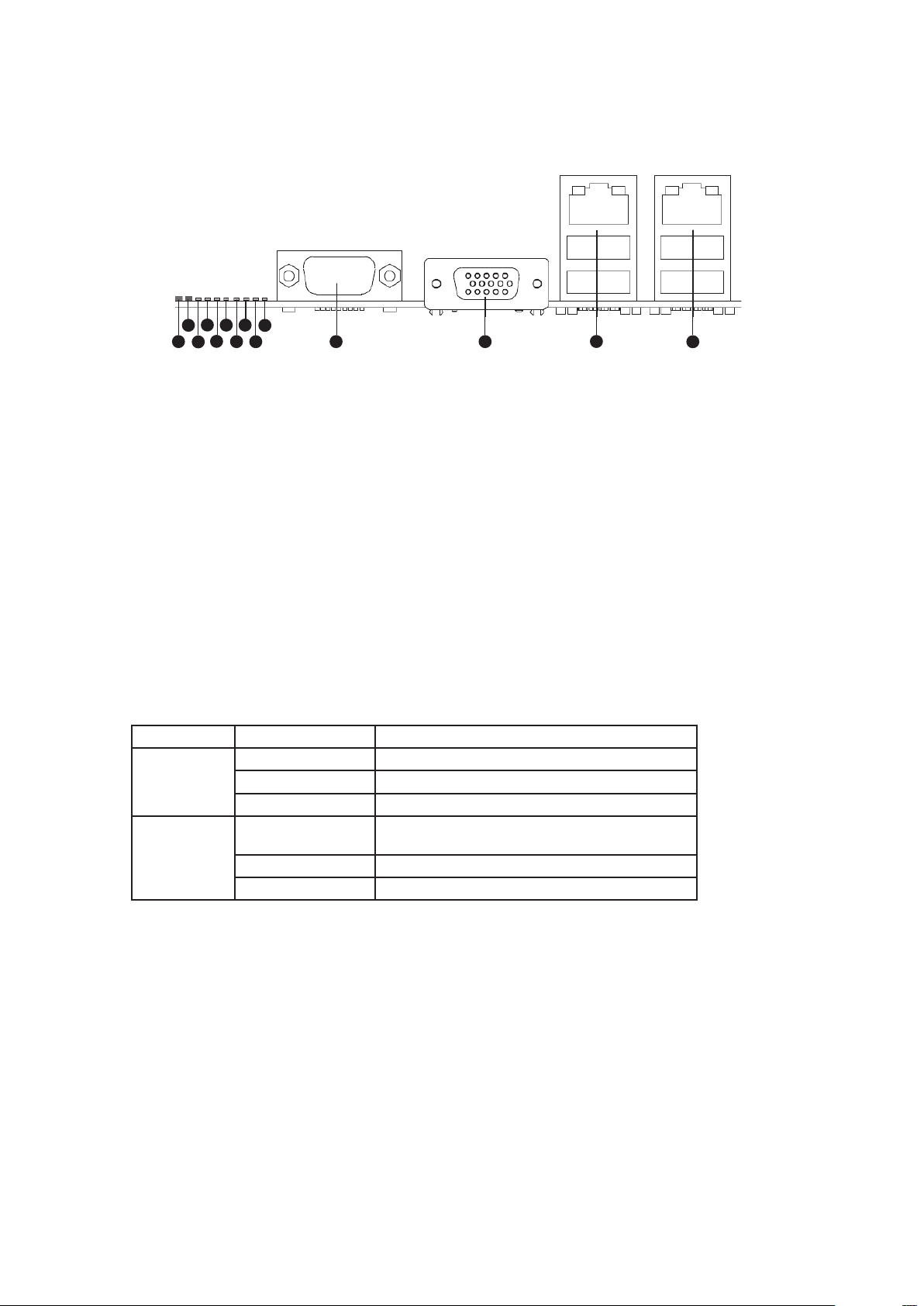
Back Panel Connectors
Figure 1. Back Panel Connectors
A. Status LED H. Diagnostic LED 2
B. System Identification LED I. Diagnostic LED 1
C. Diagnostic LED 7 (MSB LED) J. Diagnostic LED 0 (LSB LED)
D. Diagnostic LED 6 K. Serial Port A
E. Diagnostic LED 5 L. Video Port
F. Diagnostic LED 4 M. NIC 1 (top, default management port),
G. Diagnostic LED 3 N. NIC 2 (top), two USB ports (bottom)
two USB ports (bottom)
The NIC LEDs at the right and left of each NIC provide the following information.
Table 1. NIC LEDs
LED LED State Description
Left Off No network connection
Solid Amber Network connection in place
Blinking Amber Transmit/receive activity
Right Off 10 Mbps connection (if left LED is on or
blinking)
Solid Amber 100 Mbps connection
Solid Green 1000 Mbps connection
Powering up the System
G
H
I
A
B
C
D
E
F
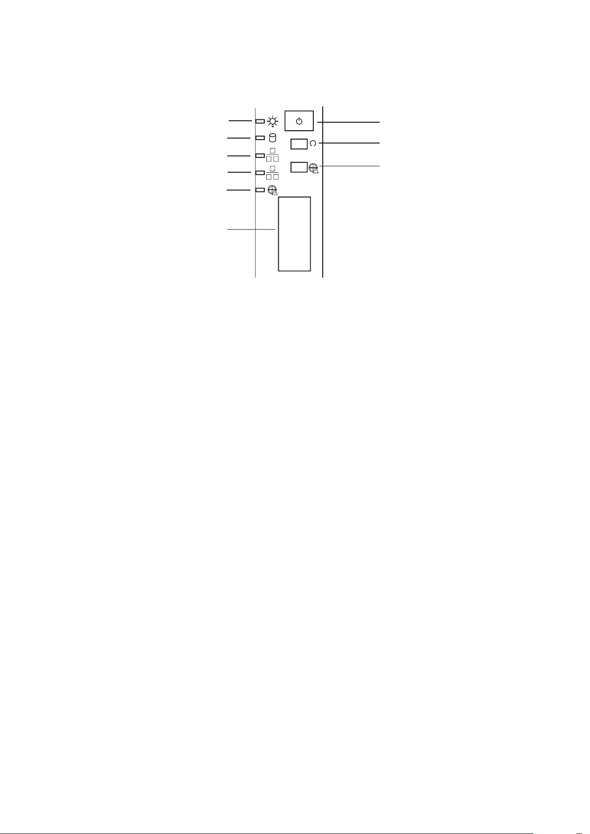
At the front of the case, you can find the neccessary controls like power button, reset button and the
HDD Leds. Press the power button one time briefly in order to boot the server.
Figure 2. Front controls and indicators
A. Power LED F. Front USB ports
B. HDD LED G. Power switch
C. NIC2 LED H. Reset switch
D. NIC1 LED I. Disable backplane alarm*
E. Critical backplane temperature*
* Only for Platinum 500 with SAS / S-ATA backplane option. A critical temperature is signaled by the backplane via LED and at the same time by an acoustic
warning. This may hint at a fan failure.
7MAXDATA Server PLATINUM 500 I M7

8
2 Server System Features
This chapter briefly describes the main features of the server system. This chapter provides a list of
server system features and diagrams showing the location of important components and connections
of the server system.
Table 2 summarizes the features of the server system.
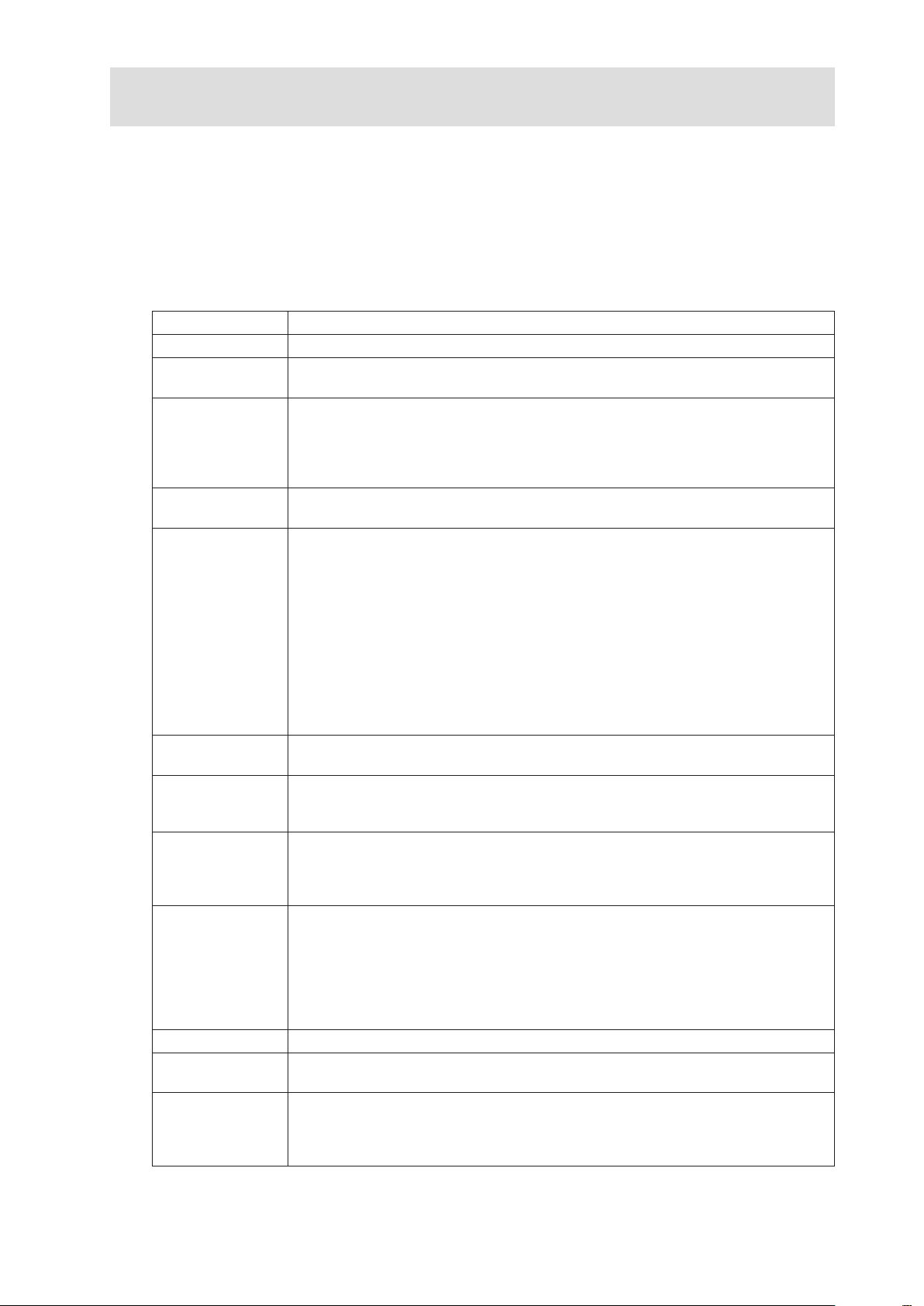
Table 2. Server System Features
Merkmal Beschreibung
Server board
Processors
System memory
Chipset
Peripheral
interfaces
Intel® S5500BC
Up to two Intel® Xeon® 5500 processors with a thermal design power (TDP) of up
to 95 W
• 8 DIMM slots, 4 per processor, distributed over two memory channels
• Up to 32 GB system memory
• 800/1066/1333 MT/s ECC registered (RDIMM) or unbuffered (UDIMM) DDR3
memory
• No mixing of RDIMMs and UDIMMs
• Intel® 5500 Chipset IOH
• Intel® 82801Jx I/O Controller Hub (ICH10R)
External connections:
• One DB-15 graphics port
• One serial DB-9 port
• Two RJ45 network ports for 10/100/1000 Mbps
• Four USB 2.0 ports (back panel)
• Two USB 2.0 ports (front)
Internal connections:
• One USB connector for two USB 2.0 ports
• One DH10 connector for serial A port
• Six SATA-II ports with integrated RAID 0/1/10 support
• One port for an optional remote management module 3
Graphics
LAN
Expansion
capabilities
HDD Cages • Up to 2 HDD cages with max. ten 2.5” or eight 3.5” HDD
Power supply Simple or redundant 600 W / 650 W power supply
Fan • Three 120 mm chassis fan
Server
management
On-board controller ServerEngines LLC Pilot II with integrated 2D video controller,
64 MB DDR2 memory, 8 MB of which is graphics memory
Two RJ45 ports for 10/100/1000 Mbps Ethernet LAN:
• One Intel® 82574L GbE controller
• One Intel® 82567 GbE controller
• Two PCI-E 2.0 x8 expansion slots
• One PCI-E 2.0 x8 expansion slot with x4 connection
• One PCI-E 1.1 x4 expansion slot
• One 5 V 32-bit / 33 MHz PCI expansion slot
a)
Drive cage for fixed 3.5” hard drives (max. 1 per system, 2 HDD supported)
b) SAS / SATA cage with four 3.5” hot-swap drive bays
c) SAS / SATA cage with six 2.5” hot-swap drive bays, expander backplane with
two 7-pin SATA connectors
• HDD cages can be combined
• SAS support through optional SAS controller
• One non-redundant fan in every power supply
• An integrated IPMI 2.0-compliant baseboard management controller
• Support for remote management module 3 (“KVM over IP”)
• Support for system management software
• Light Guided Diagnostics on replaceable units (FRUs)
10 11MAXDATA Server PLATINUM 500 I M7Server System Features
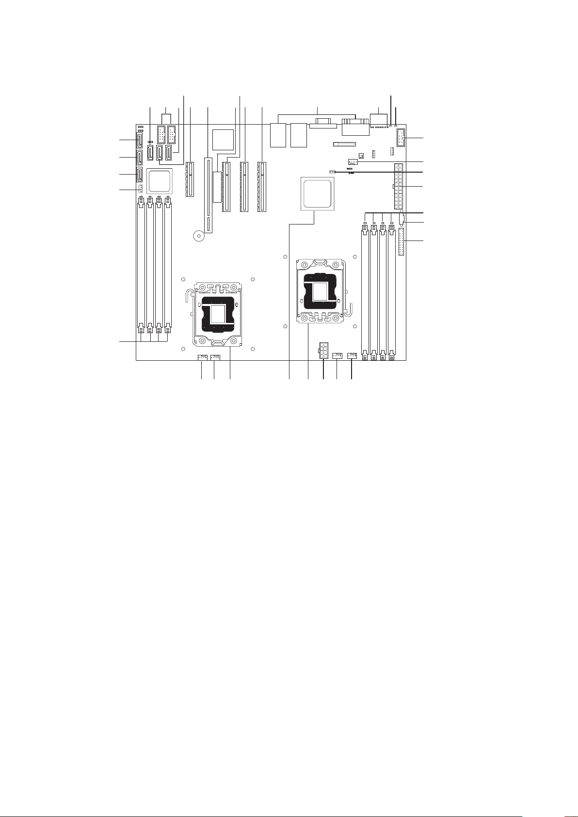
Server Board Connector and Component Locations
ICH10
AA
A B CDE
F G
H
I
J
K
L
W V
U
T
S
P
N
M
O
Q
R
X
Y
Z
BBCC
DD
EE
FF
GG
HH
Figure 3. Server Board Connector and Component Locations
A. SATA 3 R. Main power connector
B. Internal dual port USB2.0 header S. DIMM sockets of processor 1 socket (Channel A, B)
C. SATA 5 T. Power supply auxiliary connector
D. SATA 4 U. SSI 24-pin front panel connector
E. Slot 3, PCI Express x4 V. System fan 2 header
F. Slot 4, 32-bit/33 MHz PCI W. CPU 1 fan header
G. Intel® RMM3 slot X. CPU power connector
H. Slot 5, PCI Express x8 Y. CPU socket 1
I. Slot 6, PCI Express x8 (riser card) Z. Intel® IOH 5500 chipset
J. Slot 7, PCI Express x8 AA. CPU socket 2
K. Back panel I/O ports BB. CPU 2 fan header
L. Diagnostic LEDs CC. System fan 1 header
M. Status LED DD. DIMM sockets of processor 2 socket (channel D, E)
N. ID LED EE. SATA SGPIO
O. External serial B header FF. SATA 0
P. System fan 3 header GG. SATA 1
Q. SATA key HH. SATA 2
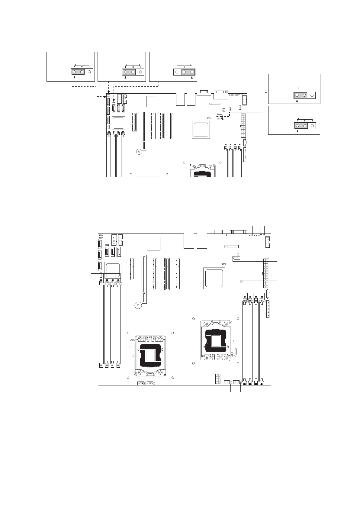
Configuration Jumpers
ICH10
C
K
J
D
I
L
F
H
G
E
B
A
ICH10
32
J8C1
J8B5
32
32
J2D2
32
J1A1
3 2
J2D1
Disable
CMOS
Clear
Enable
Recovery
BIOS
Disable
Enable
Password
Clear
Clear
Protect
Figure 4. Configuration Jumpers
Diagnostic LEDs for Light Guided Diagnostics
ME
Force
Update
BMC
Force
Update
Disable
Disable
Enable
Enable
Figure 5. Diagnostic LEDs for Light Guided Diagnostics
A. POST code diagnostic LEDs G. DIMM fault LED
B. Status LED H. System fan 2 fault LED
C. System ID LED I. CPU 1 fan fault LED
D. HDD LED J. CPU 2 fan fault LED
E. System fan 3 fault LED K. System fan 1 fault LED
F. 5 V standby LED L. DIMM fault LED
 Loading...