


MAXDATA Server PLATINUM 500 I M5
System Manual

2 3MAXDATA Server PLATINUM 500 I M5Contents

Contents
1 Setting up the System 5
Server Position ........................................................................................................................................5
Connecting the System ...........................................................................................................................6
Back Panel Connectors ......................................................................................................................6
Powering up the System .........................................................................................................................7
2 Server Board Features 9
Server Board Connector and Component Locations .............................................................................11
Configuration and BIOS Select Jumpers ...............................................................................................12
Hardware Requirements .......................................................................................................................13
Processor .........................................................................................................................................13
Memory ............................................................................................................................................13
Memory On-line Sparing ..................................................................................................................13
3 Server Board Installations and Upgrades 15
Before You Begin ..................................................................................................................................15
Tools and Supplies Needed ...................................................................................................................15
Installing and Removing Memory ..........................................................................................................15
Installing DIMMs .............................................................................................................................. 15
Removing DIMMs ............................................................................................................................ 16
Installing or Replacing the Processor ....................................................................................................17
Installing the Processor .................................................................................................................... 17
Removing the Processor .................................................................................................................. 19
Installing a PCI Card ..............................................................................................................................19
Replacing the Backup Battery ...............................................................................................................20
4 Server Utilities 23
Clearing the CMOS ...............................................................................................................................24
Clearing the Password ..........................................................................................................................25
5 Troubleshooting 27
Resetting the System ............................................................................................................................27
LED Information ....................................................................................................................................27
BIOS Error Messages ............................................................................................................................28
BIOS POST Beep Codes ......................................................................................................................29
BIOS Recovery Beep Codes .................................................................................................................29
6 Regulatory and Integration Information 31
Product Regulatory Compliance ............................................................................................................31
Product Safety Compliance .............................................................................................................. 31
Product EMC Compliance – Class A Compliance ..................................................................................31
Certifications / Registrations / Declarations ..........................................................................................31
Product Regulatory Compliance Markings ............................................................................................31
Electromagnetic Compatibility Notices .................................................................................................31
Europe (CE Declaration of Conformity) ............................................................................................31

Figures
1. Back Panel Connectors .....................................................................................................................6
2. The Controls ...................................................................................................................................... 7
3. Server Board Layout .......................................................................................................................11
4. Configuration and BIOS Select Jumper Locations ..........................................................................12
5. Installing Memory ............................................................................................................................15
6. Opening Socket Lever and Attaching Processor .............................................................................17
7. Replacing the Battery ...................................................................................................................... 21
8. Moving Clear CMOS Jumper ..........................................................................................................24
9. Moving Clear Password Jumper .....................................................................................................25
Tables
1. NIC LEDs ...........................................................................................................................................6
2. Server Board Features .......................................................................................................................9
3. Configuration Jumper [J17] ............................................................................................................. 12
4. Keyboard Commands ...................................................................................................................... 23
5. BIOS Error Messages ......................................................................................................................28
6. Beep Codes .....................................................................................................................................29
7. BIOS Recovery Beep Codes ...........................................................................................................29
8. Product Certification Markings ........................................................................................................ 31
4 MFMAXDATA Server PLATINUM 500 I M5Contents
1 Setting up the System
Server Position
Please take note of the following criteria for creating a practical and safe workplace when setting up
your computer:
The system can be used anywhere the temperature is suitable for people. However, rooms
with humidity over 70 %, and dusty or dirty areas are not appropriate. In addition, do not
expose the server to any temperatures over +30 °C or under +10 °C.
Make sure that the cables connecting the server to peripheral devices are not tight.
Make sure that all power and connection cables are positioned so that they are not trip
hazards.
When you save data to your server‘s hard disks or to a floppy disk, they are stored as
magnetic information on the media. Make sure that they are not damaged by magnetic or
electromagnetic fields.
Because the electronics in your computer can be damaged by jarring, no mechanical devices
should be placed on the same surface as the server. This is especially important for impact
printers whose vibrations could damage the hard disk.
Please take care to ensure a free air flow to the server at all times. Do not block the ventilation
slots of the server case and particularly the power supplies. An insufficient air flow may
damage the server and / or it’s components.
ATTENTION
In order to fully separate the server from current, the power cord must be removed from the wall
outlet.
ATTENTION
Safety instruction for upright devices: To ensure stability, the floor stands must be turned
outwards.
5MAXDATA Server PLATINUM 500 I M5
Connecting the System
H
G
E
A
C
F
B
D
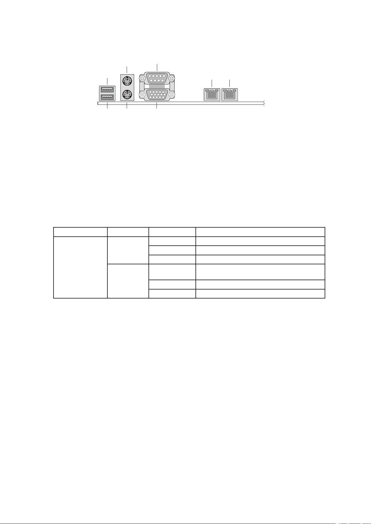
Back Panel Connectors
Figure 1. Back Panel Connectors
A. USB 1 E. Serial port A
USB 2 F. Video
B.
C. Mouse G. NIC 1 (1 Gbit)
D. Keyboard
The NIC LEDs at the right and left of each NIC provide the following information.
Table 1. NIC LEDs
H. NIC 2 (1 Gbit)
NIC LED Color LED State Description
NIC 2
(Gigabit)
Left LED Off No network connection
Solid Amber
Blinking Amber Transmit/receive activity
Right LED Off 10 Mbps connection (if left LED is on or
Solid Amber 100 Mbps connection
Solid Green 1000 Mbps connection
Network connection in place
blinking)
6 Setting up the System
Powering up the System
A
B
C
H
G
F
E
D
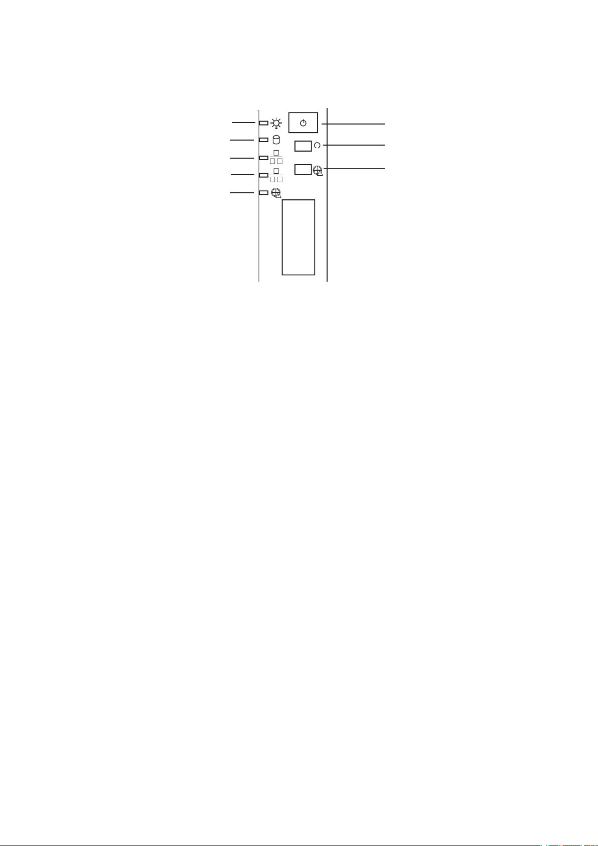
At the front of the case, you can find the neccessary controls like power button, reset button and the
HDD Leds. Press the power button one time briefly in order to boot the server.
Figure 2. The Controls
A. Power switch E. NIC1 LED
B. Reset switch F.
C. Disable Fan Warning G. HDD LED
D. Fan Warning LED
NIC2 LED
H. Power LED
7MAXDATA Server PLATINUM 500 I M5

8
2 Server Board Features
This chapter briefly describes the main features of the Server Board. This chapter provides a photograph
of the product, a list of server board features, and diagrams showing the location of important
components and connections on the server boards.
The Server Board includes dual-channel Serial ATA and Parallel ATA support. RAID 0 and 1 support
is provided for Serial ATA drives.
The Server Board is shown below.
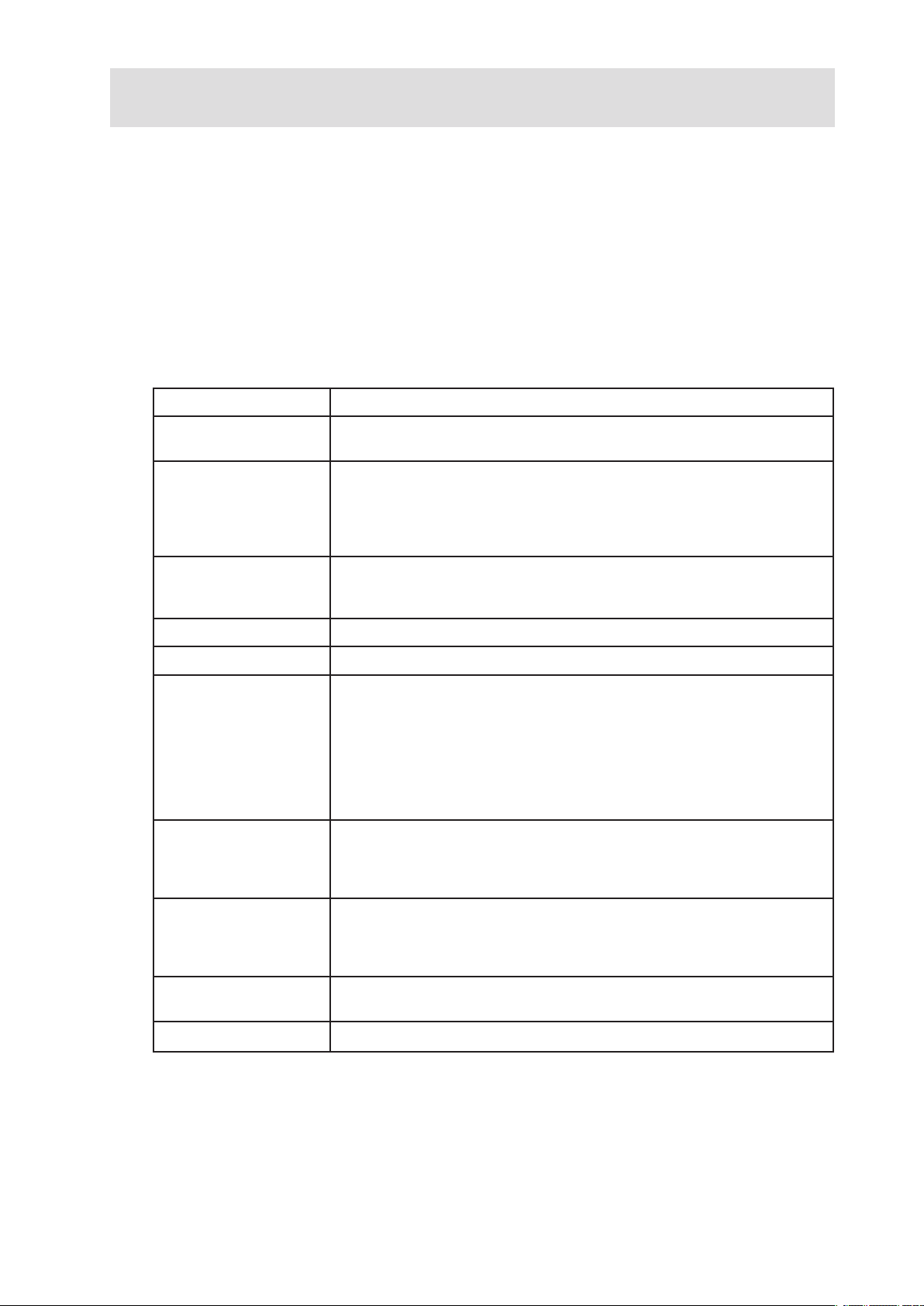
Table 2 summarizes the major features of the Server Board.
Table 2. Server Board Features
Feature Description
Processors Support for two Intel
two 604-pin Intel® Xeon™ processor sockets
Memory • Four 240-pin DDR2-400MHz SDRAM Dual Inline Memory Module
(DIMM) sockets
• Support for up to 8 GB Registered ECC system memory
• Support for single-sided or double-sided DDR2-400 DIMMs
• Support for Memory Sparing
®
Xeon™ processors with an 800 MHz system bus in
Chipset Intel® E7320 chipset, consisting of:
• Intel® 827320 Memory Controller Hub (MCH)
®
• Intel
6300ESB I/O Controller Hub (ICH5-R)
Firmware Hub (FWH) 8 Megabit Firmware Hub (FWH)
I/O Control National PC87427 I/O controller chip
Peripheral Interfaces • Two external USB 2.0 ports on the back panel with an additional
internal header that provides support for two additional USB ports for
support at the front of the chassis (four total possible USB 2.0 ports)
• One serial port and one serial port header
• One ATA interface with Ultra 33, 66 and 100 DMA mode
• Two serial ATA connectors with support for RAID 0 and 1
• One floppy drive interface with support for one drive
• PS/2 keyboard and mouse ports
LAN • NIC1: One Marvell Yukon*-EC 88E8050 Platform LAN Connect (PLC)
device for 10/100/1000 Mbps Ethernet LAN connectivity
• NIC2: One Intel
connectivity
Expansion Capabilities Three independent PCI buses:
• One x8 PCI-Express* connector (attached to x4 bus). Slot 4
• Two 64-bit/66MHz, 3.3V PCI-X* connectors. Slots 1 and 2
• Two 32-bit/33MHz, 5V PCI connectors. Slots 3 and 5
Integrated Capabilities • Integrated 2D/3D graphics controller: ATI Rage™ XL Video Controller
with 8 MB of SDRAM
®
82541P1 controller for 10/100/1000 Mbps Ethernet LAN
Fans Support for up to three system fans and two processor fans
continued

Server Board Features (Continued)
BIOS Intel®/AMI BIOS with support for:
• Advanced Configuration and Power Interface (ACPI)
• 8 megabit symmetrical flash memory
• Support for SMBIOS
Power Management Support for ACPI:
• Wake on USB, PCI, RS-232, PS/2, LAN, and control panel
Server Management
• Intel® Server Management 8.x support for host-based support. (no outof-band support)
10 11MAXDATA Server PLATINUM 500 I M5Server Board Features
 Loading...