

Maxdata 2200 IR M6 user manual

MAXDATA Server PLATINUM 2200 IR M6
User’s Manual

2

Contents
1 Setting up the System 7
Server Position ........................................................................................................................................7
Connecting the System ...........................................................................................................................8
Rear of Server System .......................................................................................................................8
Standard Control Panel ............................................................................................................................9
Local Control Panel ................................................................................................................................10
2 Server System Features 11
Connector and Header Locations ..........................................................................................................12
Configuration Jumpers ..........................................................................................................................13
Light Guided Diagnostics ......................................................................................................................14
RAID Support ........................................................................................................................................15
Hardware Requirements .......................................................................................................................15
Processor .........................................................................................................................................15
Memory ............................................................................................................................................15
Memory Sparing and Mirroring ........................................................................................................16
Optional Hardware ................................................................................................................................16
Remote Management Module .........................................................................................................16
3 Server Chassis Features 17
Component Identification ......................................................................................................................17
Internal Components ........................................................................................................................17
SAS/SATA Mid-Planes ...........................................................................................................................18
Hot-Swap SAS/SATA Backplane ...........................................................................................................19
Peripheral Devices .................................................................................................................................20
4 Hardware Installations and Upgrades 21
Before You Begin ..................................................................................................................................21
Tools and Supplies Needed ..............................................................................................................21
System References ..........................................................................................................................21
Removing and Installing the Chassis Cover ..........................................................................................21
Removing and Installing the Front Bezel ...............................................................................................22
Removing the Front Bezel ................................................................................................................22
Installing the Front Bezel ..................................................................................................................22
Installing a SAS or SATA Hot-swap Hard Disk Drive .............................................................................23
Removing a Hot-swap Hard Disk Drive .................................................................................................24
Removing and Installing the PCI Riser Assembly .................................................................................25
Removing the PCI Riser Assembly ..................................................................................................25
Installing the PCI Riser Assembly ....................................................................................................25
Installing a PCI Add-in Card ..............................................................................................................26
Installing or Replacing a Hot-swap Power Supply .................................................................................27
Removing a Hot-swap Power Supply ...............................................................................................27
Filling Empty Chassis Bays ....................................................................................................................27
Installing Memory ..................................................................................................................................28
Installing DIMMs ..............................................................................................................................28
Installing or Replacing the Processor ....................................................................................................29
Installing the Processor ....................................................................................................................29
Installing the Heat Sink(s) .................................................................................................................30
Removing a Processor .....................................................................................................................31
RJ45 Serial Port Configuration ..............................................................................................................32
Replacing the Backup Battery ...............................................................................................................33
3MAXDATA Server PLATINUM 2200 IR M6

5 Server Utilities 35
Using the BIOS Setup Utility .................................................................................................................35
Starting Setup ...................................................................................................................................35
If You Cannot Access Setup .............................................................................................................35
Setup Menus ....................................................................................................................................35
Clearing the Password ..........................................................................................................................37
Clearing the CMOS ...............................................................................................................................37
6 Troubleshooting 39
LED Information ....................................................................................................................................39
BIOS POST Beep Codes .......................................................................................................................40
7 Technical Reference 41
Power Supply Specifications .................................................................................................................41
750-W Single Power Supply Input Voltages ..................................................................................... 41
750-W Single Power Supply Output Voltages .................................................................................. 41
System Environmental Specifications ...................................................................................................41
8 Regulatory and Integration Information 43
Product Regulatory Compliance ............................................................................................................43
Product Safety Compliance ..............................................................................................................43
Product EMC Compliance ...............................................................................................................43
Product Regulatory Compliance Markings .......................................................................................43
Product RoHS Compliance ...............................................................................................................43
Installation Precautions .........................................................................................................................43
Use Only for Intended Applications .......................................................................................................44
Power and Electrical Warnings ..............................................................................................................44
Rack Mount Warnings ...........................................................................................................................44
4 Contents

Figures
1. Server System Back ..........................................................................................................................8
2. Standard Control Panel ......................................................................................................................9
3. Local Control Panel .........................................................................................................................10
4. Server Board Connector and Component Locations .......................................................................12
5. BIOS Select Jumper ........................................................................................................................13
6. Recovery Jumpers ..........................................................................................................................13
7. Light Guided Diagnostic LEDs .........................................................................................................14
8. DIMM Configuration Diagram .........................................................................................................15
9. Internal Component Locations ........................................................................................................17
10. Passive Mid-Plane Components ......................................................................................................18
11. Active SAS/SATA Mid-Plane Components ......................................................................................18
12. Hot-Swap SAS/SATA Backplane Components (Front View) ...........................................................19
13. Hot-Swap SAS/SATA Backplane Components (Rear View) ............................................................19
14. Optional Peripherals ........................................................................................................................20
15. Removing the Chassis Cover ..........................................................................................................21
16. Removing the Front Bezel ...............................................................................................................22
17. Removing the Hot-swap Hard Drive Carrier from the Chassis ........................................................23
18. Removing the Retention Device from the Hot-swap Drive Carrier .................................................23
19. Attaching a Hot-swap Hard Disk Drive to a Drive Carrier ................................................................24
20. Removing the PCI Riser Assembly from the Chassis .....................................................................25
21. Installing a PCI Add-in Card .............................................................................................................26
22. Removing a Hot-swap Power Supply ..............................................................................................27
23. Installing Memory ............................................................................................................................28
24. Lifting the Processor Socket Handle ...............................................................................................29
25. Installing the Processor ...................................................................................................................29
26. Removing the Socket Cover ............................................................................................................30
27. Installing Heat Sink ..........................................................................................................................31
28. Changing the Serial Port Configuration ...........................................................................................32
29. Replacing the Backup Battery .........................................................................................................34
Tables
1. NIC LEDs ...........................................................................................................................................8
2. Standard Control Panel Features .......................................................................................................9
3. Local Control Panel Features ...........................................................................................................10
4. Server System Features ..................................................................................................................11
5. Keyboard Commands ......................................................................................................................36
6. LED Information ..............................................................................................................................39
7. POST Error Beep Codes ..................................................................................................................40
8. Error Beep Codes Provided by Remote Management Modules .....................................................40
9. 750-W Power Supply System Output Capability ............................................................................. 41
10. Environmental Specifications ..........................................................................................................41
11. Product Certification Markings ........................................................................................................43
5MAXDATA Server PLATINUM 2200 IR M6

6
1 Setting up the System
Server Position
Please take note of the following criteria for creating a practical and safe workplace when setting up
your computer:
The system can be used anywhere the temperature is suitable for people. However, rooms
with humidity over 70%, and dusty or dirty areas are not appropriate. In addition, do not
expose the server to any temperatures over +30 °C or under +10 °C.
Make sure that the cables connecting the server to peripheral devices are not tight.
Make sure that all power and connection cables are positioned so that they are not trip
hazards.
When you save data to your server‘s hard disks or to a floppy disk, they are stored as
magnetic information on the media. Make sure that they are not damaged by magnetic or
electromagnetic fields.
Because the electronics in your computer can be damaged by jarring, no mechanical devices
should be placed on the same surface as the server. This is especially important for impact
printers whose vibrations could damage the hard disk.
Please take care to ensure a free air flow to the server at all times. Do not block the ventilation
slots of the server case and particularly the power supplies. An insufficient air flow may
damage the server and / or it’s components.
ATTENTION
In order to fully separate the server from current, the power cord must be removed from the wall
outlet.
7MAXDATA Server PLATINUM 2200 IR M6
Connecting the System
A B
P
O
N
M
KL
J
I
D
GH EF
C
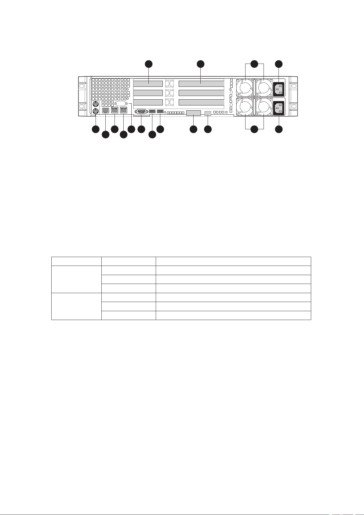
Rear of Server System
A. Low Profile Add-in Card Slots I. USB 6
B. Full Height PCI Add-in Card Slots J.
C. Upper Power Supply Module K. Video
D. Upper Power Receptacle
E. Lower Power Receptacle M. NIC 2
F. Lower Power Supply Module (optional)
G. Server Management NIC (optional) O. RJ45 Serial B Connector
H. I/O Module (optional) P. PS2 Keyboard and Mouse Connectors
Figure 1. Server System Back
USB 5
L. DB-9 Serial A Connector
N. NIC 1
Table 1. NIC LEDs
LED Color LED State Description
Left LED Off
Solid Amber
Blinking Amber Transmit/receive activity
Right LED Off 10 Mbps connection (if left LED is on or blinking)
Solid Amber 100 Mbps connection
Solid Green 1000 Mbps connection
No network connection
Network connection in place
8 Setting up the System
Standard Control Panel
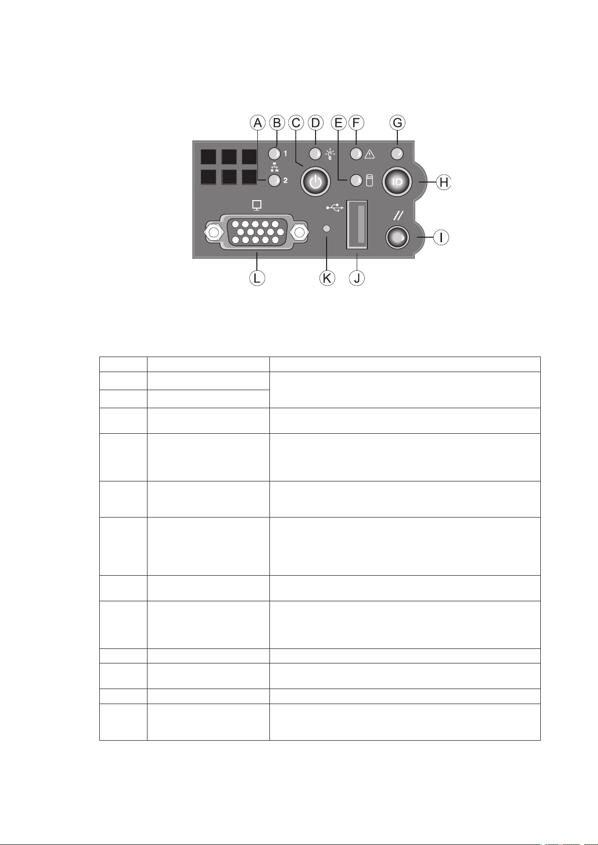
The diagram below shows the features available on the Standard Control Panel. The Standard Control
Panel is one of two required control options that can be selected. The other option is the Local Control
Panel.
Figure 2. Standard Control Panel
Table 2. Standard Control Panel Features
Callout Feature Function
A. NIC 2 activity LED Continuous green light indicates a link between the system
B. NIC 1 activity LED
C. Power/Sleep button Toggles the system power on/off. Sleep button for ACPI
D. Power/Sleep LED
E. Hard disk drive activity
LED
F. System Fault LED Solid green indicates normal operation
G. System Identification LED Solid blue indicates system identification is active
H. System Identification
button
I. Reset button Reboots and initializes the system.
J. USB 2.0 port Allows you to attach a USB component to the front of the
K. NMI button Puts the server in a halt-state for diagnostic purposes.
L. Video port Allows you to attach a video monitor to the front of the
and the network to which it is connected.
Blinking green light indicates network activity.
compatible operating systems.
Continuous green light indicates the system has power
applied to it. Blinking green indicates the system is in S1
sleep state.
No light indicates the power is off / is in ACPI S4 or S5 state.
Random blinking green light indicates hard disk drive activity
(SCSI or SATA).
No light indicates no hard disk drive activity.
Blinking green indicates degraded performance
Solid amber indicates a critical or non-recoverable condition
Blinking amber indicates a non-critical condition
No light indicates POST is running or the system is off.
No light indicates system identification is not activated
Toggles the front panel ID LED and the baseboard ID LED
on and off. The baseboard LED is visible from the rear of the
chassis and allows you to locate the server from the rear of a
rack of systems.
chassis.
chassis. The front and rear video ports cannot be used at the
same time.
9MAXDATA Server PLATINUM 2200 IR M6
Local Control Panel
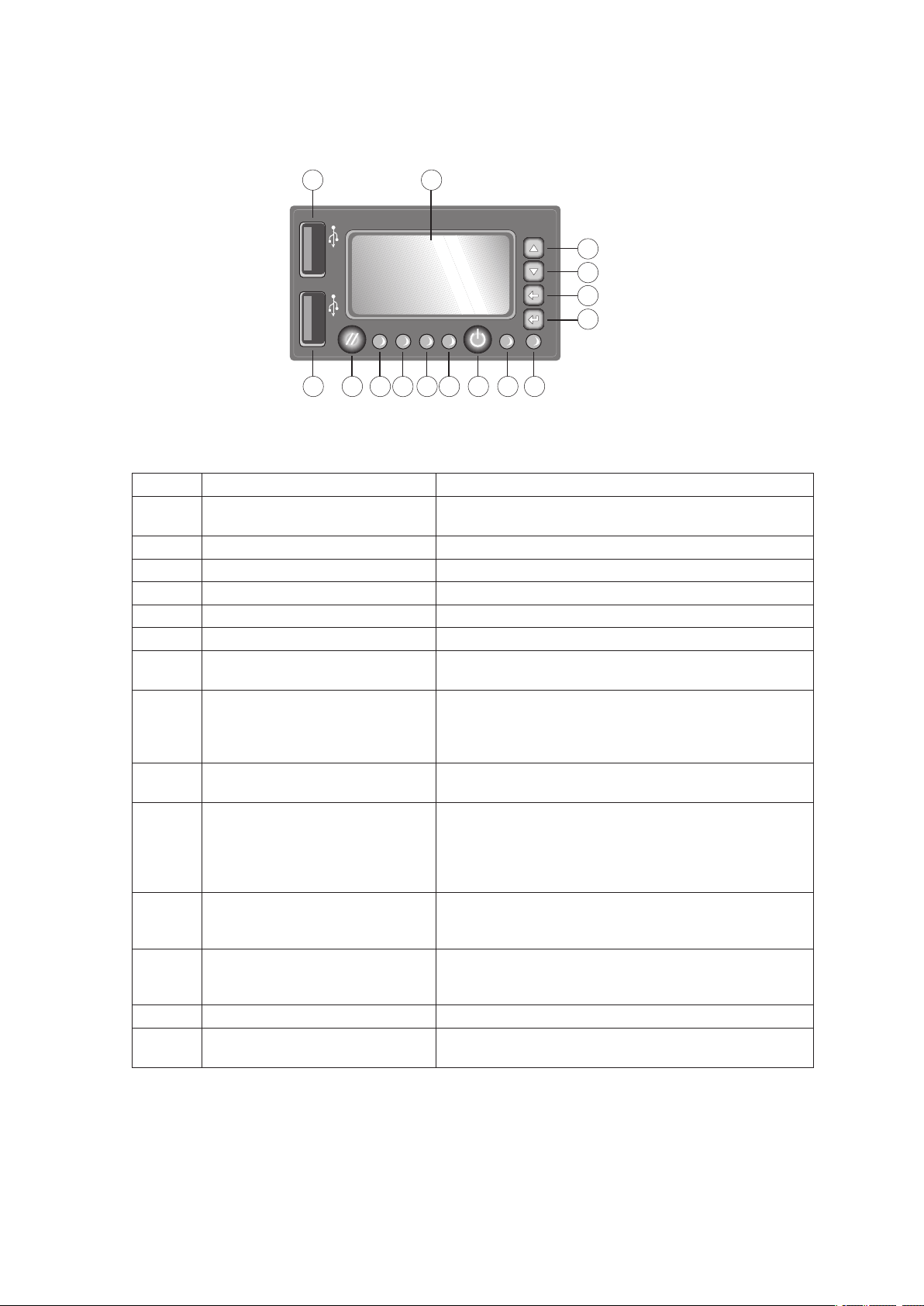
The diagram below shows the features available on the Local Control Panel. The Local Control Panel
is one of two required control options that can be selected.
Figure 3. Local Control Panel
Table 3. Local Control Panel Features
Callout Feature Function
A. USB 2.0 port Allows you to attach a USB component to the front of
the chassis.
B.
C. Menu control button, scroll up Scroll up one option at a time.
D. Menu control button, scroll down Scroll down one option at a time.
E. Menu control button, scroll left Move to the previous option.
F. Menu control button, scroll right Move to the previous page.
G. System Identification LED Solid blue indicates system identification is active. No
H. Power/Sleep LED Continuous green light indicates the system has power
I. Power/Sleep button Toggles the system power on/off. Sleep button for ACPI
J. System Status LED Solid green indicates normal operation. Blinking green
L.
K.
M. Hard disk drive status LED Random blinking green light indicates hard disk drive
N. Reset button Reboots and initializes the system.
O. USB 2.0 port Allows you to attach a USB component to the front of
LCD display Screen on which system information is displayed.
light indicates system identification is not activated.
applied to it. Blinking green indicates the system is in
S1 sleep state. No light indicates the power is off / is in
ACPI S4 or S5 state.
compatible operating systems.
indicates degraded performance. Solid amber indicates
a critical or non-recoverable condition. Blinking amber
indicates a non-critical condition. No light indicates
POST is running or the system is off.
NIC 1 activity LED
NIC 2 activity LED
Continuous green light indicates a link between the
system and the network to which it is connected.
Blinking green light indicates network activity.
activity. No light indicates no hard disk drive activity is
taking place
the chassis.
10 Setting up the System
2 Server System Features
This chapter briefly describes the main features of the MAXDATA PLATINUM Server System.
It provides a list of the server system features and diagrams showing the location of important
components and connections on the server system.
Table 4 summarizes the major features of the server system.
Table 4. Server System Features
Feature Description
Dimensions
Server Board
Processor Support for up to two Dual-Core Intel
Memory
Chipset Intel® 5000P chipset, consisting of:
Peripheral Interfaces
• 87.30 mm high
• 430 mm wide
• 704.8 mm deep
• 29.5 kg max chassis weight
Intel® Server Board S5000PAL
®
Xeon® processors 5000 sequence
• Eight DIMM slots supporting stacked DDR2 533/667 MHz FBDIMM memory
• Support for up to 32 GB DDR2 533/667 MHz FBDIMM memory
• Intel® 5000P Memory Controller Hub (MCH)
• Intel® 6321ESB I/O Controller Hub
External connections:
• Stacked PS/2 ports for keyboard and mouse
• RJ45 Serial B port
• Two RJ45 NIC connectors for 10/100/1000 Mb connections
• Two USB 2.0 ports
Internal connections:
• One USB port header, which supports two USB 2.0 ports
• One DH10 Serial A header
• Six Serial ATA 150 connectors with integrated RAID 0/1 support
• One ATA-100 44-pin connector for optical drive support
• SSI-compliant 24-pin control panel header
• SSI-compliant 24-pin main power connector, supporting the ATX-12V
standard on the first 20 pins
I/O Controll National Semiconductor PC87427 controller
Video On-board ATI ES1000 video controller with 16 MB DDR SDRAM
LAN Intel® 82563EB dual port controller for 10/100/1000 Mbit/sec Ethernet LAN
connectivity
Expansion
Capabilities
Hard Drives
Peripherals
Power Supply Up to two 750 W power supply modules
Fans
USB
System Management
• One low profile riser slot supporting 2U PCI Express riser cards
• One full height riser slot supporting 2U PCI-X and PCI Express riser cards
• Five hot-swap SATA/SAS drives
• Drive bay for sixth hot-swap SATA/SAS drive or a 3.5 inch tape drive
• Slimline bay for IDE optical drive
• PCI riser card bracket
• Either non-redundant three fan option or redundant fan module option
containing six fans
• Two non-redundant fans in power supply
• Two front panel USB ports
• One internal USB header providing two USB ports
IPMI 2.0 compliant platform instrumentation Light Guided Diagnostics
11MAXDATA Server PLATINUM 2200 IR M6
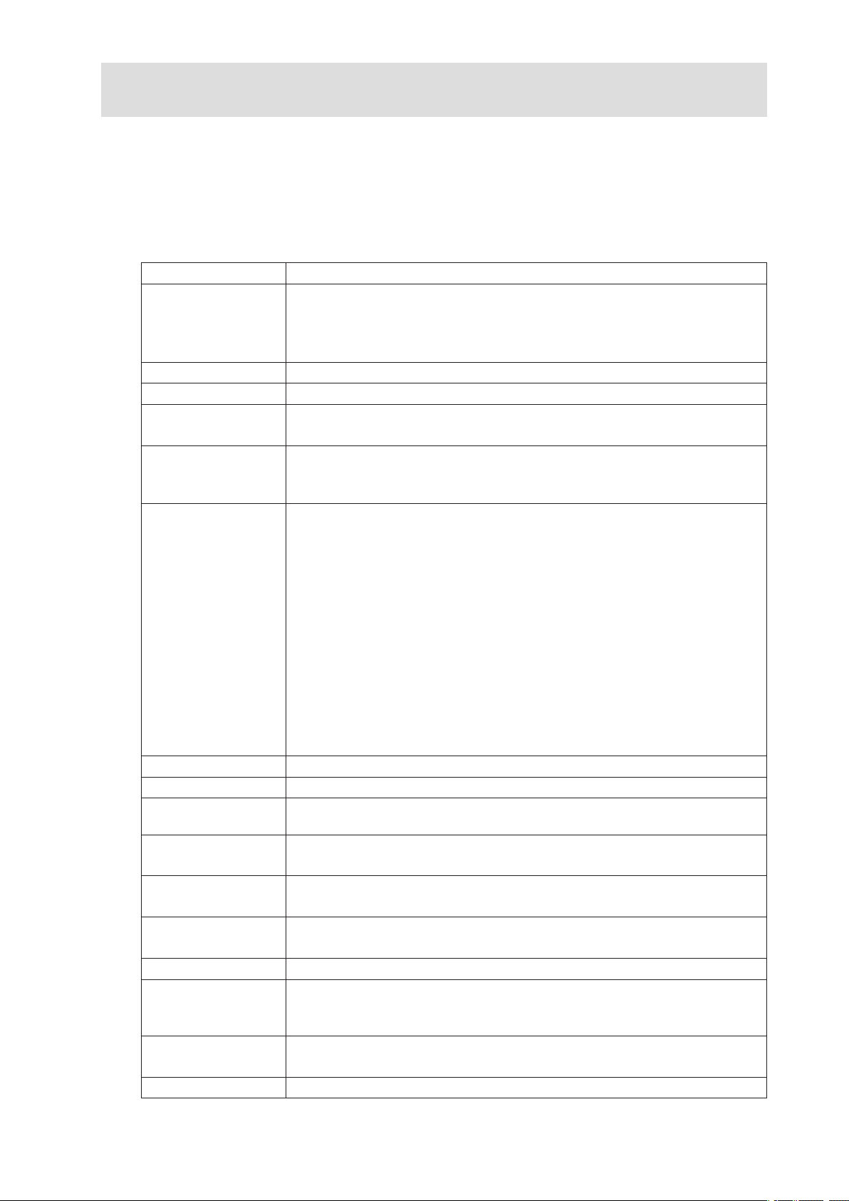
Connector and Header Locations
M
N
O
L
J
K
V
U
S
T
R
W
Q
P
PP
MM
LL
KK
II
HH
GG
FF
EE
DD
CC
BB
AA
Z
Y
X
B
A
E
D
F
H
G
C
I
NN
OO
QQ
JJ
Figure 4. Server Board Connector and Component Locations
A. BIOS Bank Select Jumper P. Processor 2 Socket DD. SATA Port 0
Intel® 6321ESB IO Controller
B.
Hub
C. I/O Expansion Module
Connector
D. POST Code Diagnostic LEDs S. Processor Fan 2 Header
E. Intel® Adaptive Slot - Full
Height
F. PCI Express Riser Slot - Low
Profile
G. System Identification LED
- Blue
H. Back Panel I/O Ports W. CPU Power Connector KK.
I. Status LED - Green/Amber X. Main Power Connector LL. System Recovery
J. Serial B Configuration
Jumper
K. System Fan 4 Header Z. Power Supply Manage-
L. System Fan 3 Header AA. Dual Port USB 2.0 Header OO. Local Control Panel
M. DIMM Sockets BB. System Fan 1 Header PP. Serial A Header
N. Intel® 5000P MCH CC. 24-pin SSI Control Panel
O. Processor 1 Socket
Q. Processor Fan 1 Header EE. SATA Port 1
R. Voltage Regulator Heat
Sink
T. Bridge Board Connector HH. SATA Port 4
U. ATA-100 Optical Drive
Connector (Power + IO)
V. System Fan 2 Header JJ. SATA SW RAID 5 Activa-
Y. Battery
ment Connector
Connector
FF. SATA Port 2
GG. SATA Port 3
II. SATA Port 5
tion Key Connector
Remote Management
Module (RMM) Connector
Jumpers
MM. Chassis Intrusion Switch
Header
NN. 3-pin IPMB Header
Header
QQ. RMM NIC Connector
12 Server System Features
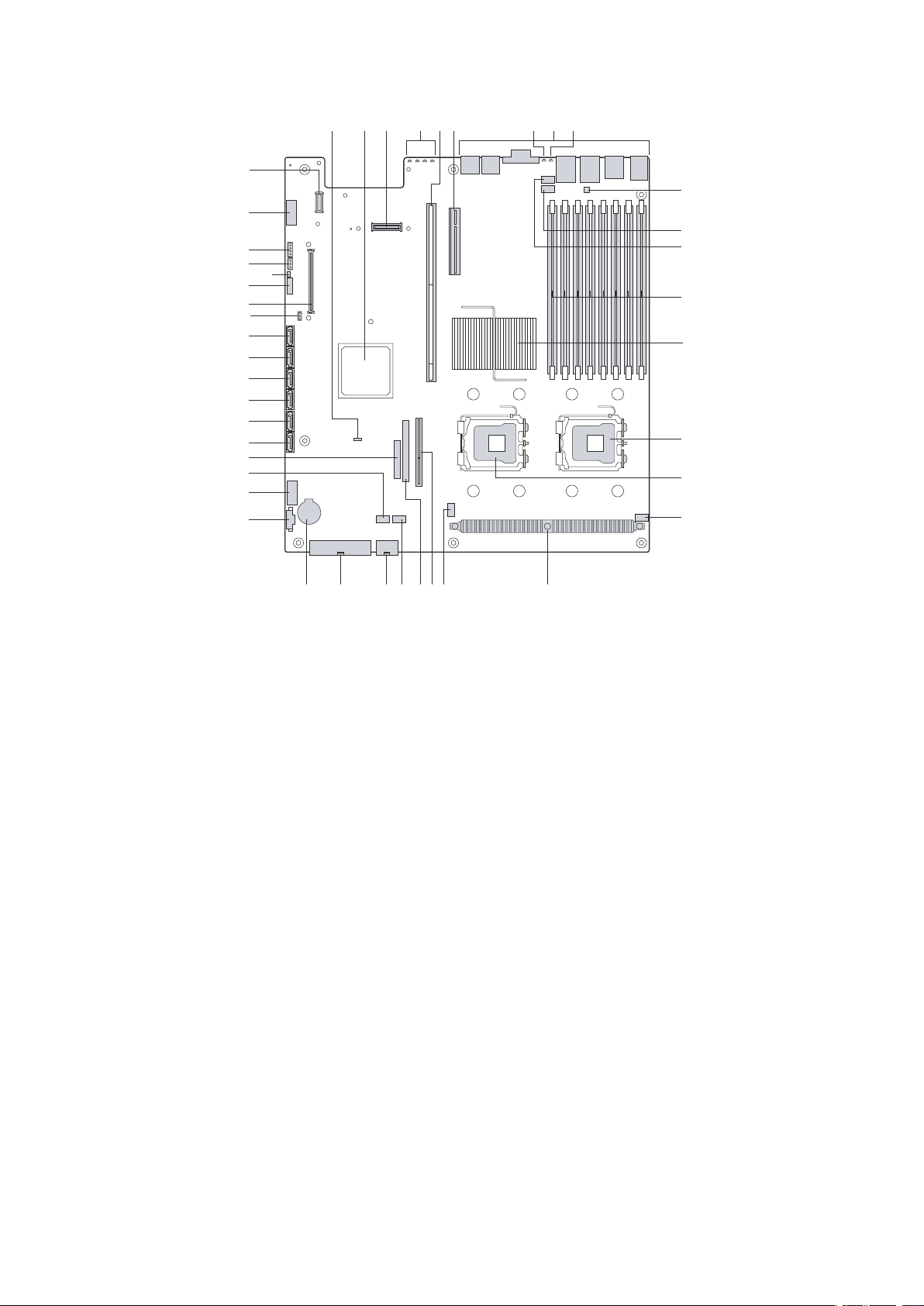
Configuration Jumpers
3
BIOS Select
1-2: Force
Lower Bank
2-3: Normal
Operation (Default)
3
J3H1
3
2
Password
Reset
J1D2
J1D3
3
2
Clear
CMOS
BMC Force
Update Mode
3
2
J1D1
Disab
le
Enab
le
Figure 5. BIOS Select Jumper
Jumper Name Jumper Purpose
BIOS Select If pins 1-2 are jumpered, the BIOS in the lower bank will be
selected on the next reset. These pins should be jumpered on 2-3
for normal operation.
Figure 6. Recovery Jumpers
Jumper Name Jumper Purpose
CMOS Clear If pins 2-3 are jumpered, the CMOS settings will be cleared on the next reset.
Password Clear If pins 2-3 are jumpered, administrator and user passwords will be cleared on
BMC Force Update
Mode
These pins should be jumpered on 1-2 for normal operation.
the next reset. These pins should be jumpered on 1-2 for normal operation.
If pins 2-3 are jumpered, BMC Force Update Mode is enabled. These pins
should be jumpered on 1-2 for normal operation.
13MAXDATA Server PLATINUM 2200 IR M6
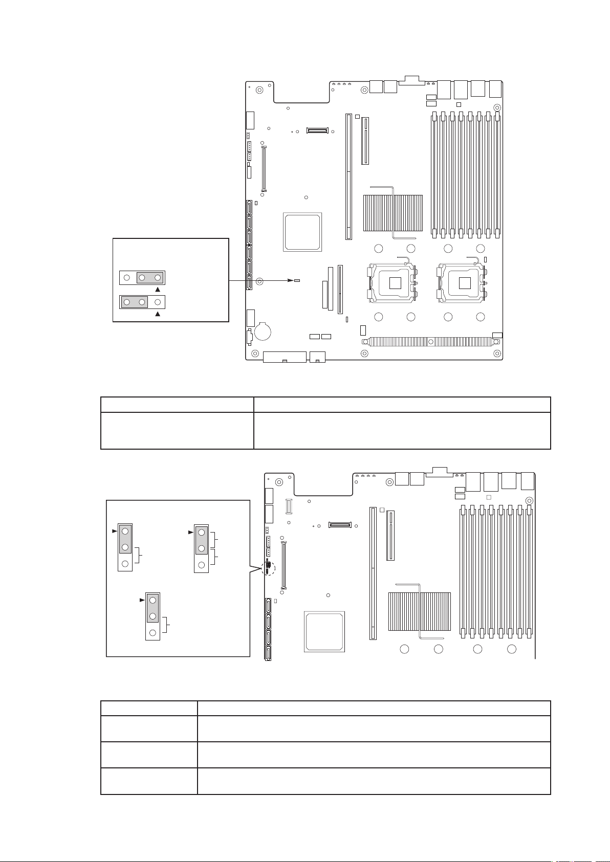
Light Guided Diagnostics
1
A
M
M
I
D
2A MMID
1
B
MMI
D
2B MMID
1
C
M
M
I
D
2C MMID
1
D
MMI
D
2D MMID
G
D
E
F
I
J
H
K
N
L
M
C
B
A
The server board contains diagnostic LEDs to help you identify failed and failing components, and to
help you identify the server from among several servers. Except for the ID LED, the status LED, and
the 5V standby LED, the LEDs turn on (amber) only if a failure occurs.
Figure 7. Light Guided Diagnostic LEDs
A. POST Code LEDs H. DIMM C1 Fault
ID LED I. DIMM C2 Fault
B.
C. Status LED J. DIMM D1 Fault
D. DIMM A1 Fault
K. DIMM D2 Fault
E. DIMM A2 Fault L. CPU 1 Fault
F. DIMM B1 Fault M. CPU 2 Fault
G. DIMM B2 Fault N. 5V Standby
14 Server System Features
 Loading...