


MAXDATA Server PLATINUM 2200 IR M5
User’s Manual

2

Contents
1 Setting up the System 7
Server Position ........................................................................................................................................7
Connecting the System ...........................................................................................................................8
Back Panel Connectors ......................................................................................................................8
Standard Control Panel ............................................................................................................................9
2 Server Board Features 11
Connector and Header Locations ..........................................................................................................13
Configuration Jumpers ..........................................................................................................................14
Hardware Requirements .......................................................................................................................15
Processor .........................................................................................................................................15
Memory ............................................................................................................................................15
Memory Sparing and Mirroring ........................................................................................................16
Optional Hardware ................................................................................................................................17
Intel® Management Module .............................................................................................................17
Local Control Panel ...........................................................................................................................17
3 Server Chassis Features 19
Component Identification ......................................................................................................................20
Internal Components ........................................................................................................................20
SCSI Backplane Connections ................................................................................................................21
Local Control Panel ................................................................................................................................22
Back Panel Features ..............................................................................................................................23
Peripheral Devices .................................................................................................................................23
4 Hardware Installations and Upgrades 25
Before You Begin ..................................................................................................................................25
Tools and Supplies Needed ..............................................................................................................25
System References ..........................................................................................................................25
Removing and Installing the Chassis Cover ..........................................................................................25
Removing and Installing the Front Bezel ...............................................................................................26
Removing the Front Bezel ................................................................................................................26
Installing the Front Bezel ..................................................................................................................26
Installing a SCSI Hot-swap Hard Disk Drive ..........................................................................................27
Removing a SCSI Hot-swap Hard Disk Drive ........................................................................................28
Removing and Installing the PCI Riser Assembly .................................................................................29
Removing the PCI Riser Assembly ..................................................................................................29
Installing the PCI Riser Assembly ....................................................................................................29
Installing a PCI Add-in Card ..............................................................................................................30
Installing or Replacing a Hot-swap Power Supply .................................................................................31
Removing a Hot-swap Power Supply ...............................................................................................31
Filling Empty Chassis Bays ....................................................................................................................31
Installing and Removing Memory ..........................................................................................................32
Installing DIMMs ..............................................................................................................................32
Installing or Replacing the Processor ....................................................................................................33
Installing the Processor ....................................................................................................................33
Installing the Heat Sink(s) .................................................................................................................34
Removing a Processor .....................................................................................................................35
RJ45 Serial Port Configuration ..............................................................................................................36
Replacing the Backup Battery ...............................................................................................................37
3MAXDATA Server PLATINUM 2200 IR M5

5 Server Utilities 39
Using the BIOS Setup Utility .................................................................................................................39
Starting Setup ...................................................................................................................................39
If You Cannot Access Setup .............................................................................................................39
Setup Menus .................................................................................................................................... 39
Clearing the Password ..........................................................................................................................41
Clearing the CMOS ...............................................................................................................................41
6 Troubleshooting 43
LED Information ....................................................................................................................................43
BIOS POST Beep Codes .......................................................................................................................44
7 Technical Reference 45
Power Supply Specifications .................................................................................................................45
700-W Single Power Supply Input Voltages ..................................................................................... 45
700-W Single Power Supply Output Voltages .................................................................................. 45
System Environmental Specifications ...................................................................................................45
8 Regulatory and Integration Information 47
Product Regulatory Compliance ............................................................................................................47
Product Safety Compliance ..............................................................................................................47
Product EMC Compliance ....................................................................................................................47
Product Regulatory Compliance Markings ............................................................................................47
Electromagnetic Compatibility Notices .................................................................................................48
FCC (USA) ........................................................................................................................................48
Europe (CE Declaration of Conformity) ............................................................................................48
Installation Precautions .........................................................................................................................48
Installation Requirements ......................................................................................................................49
Prevent Power Supply Overload ......................................................................................................49
Place Battery Marking ......................................................................................................................49
Use Only for Intended Applications .......................................................................................................49
4 Contents

Figures
1. Back Panel Connectors .....................................................................................................................8
2. Standard Control Panel Features ....................................................................................................... 9
3. Server Board Connector and Component Locations .......................................................................13
4. Configuration Jumper Locations .....................................................................................................14
5. Internal Component Locations ........................................................................................................20
6. Rear of SCSI Backplane ...................................................................................................................21
7. Local Control Panel .........................................................................................................................22
8. Chassis Back ...................................................................................................................................23
9. Optional Peripherals ........................................................................................................................23
10. Removing the Chassis Cover ..........................................................................................................25
11. Removing Front Bezel ..................................................................................................................... 26
12. Removing the Hot-swap Hard Drive Carrier from the Chassis ........................................................27
13. Removing the Retention Device from the Hot-swap Drive Carrier .................................................27
14. Attaching a Hot-swap Hard Disk Drive to a Drive Carrier ................................................................28
15. Removing the PCI Riser Assembly from the Chassis .....................................................................29
16. Installing a PCI Add-in Card .............................................................................................................30
17. Removing a Hot-swap Power Supply ..............................................................................................31
18. Installing Memory ............................................................................................................................32
19. Opening Socket Lever .....................................................................................................................33
20. Inserting Processor ........................................................................................................................34
21. Installung Heat Sink .........................................................................................................................34
22. Changing the Serial Port Configuration ...........................................................................................36
23. Replacing the Backup Battery .........................................................................................................38
Tables
1. NIC LEDs ........................................................................................................................................... 8
2. Standard Control Panel Features ....................................................................................................... 9
3. Front Panel LED Description ...........................................................................................................10
4. Server Board Features .....................................................................................................................11
5. Configuration Jumper ...................................................................................................................... 14
6. DIMM Module Memory Capacity Support ......................................................................................15
7. Server Chassis Features ..................................................................................................................19
8. Local Control Panel Features ...........................................................................................................22
9. Keyboard Commands ......................................................................................................................40
10. LED Information ..............................................................................................................................43
11. POST Error Beep Codes ..................................................................................................................44
12. Error Beep Codes Provided by Intel® Management Modules .........................................................44
13. 700-W Power Supply System Output Capability .............................................................................45
14. Environmental Specifications ..........................................................................................................45
15. Product Certification Markings ........................................................................................................47
5MAXDATA Server PLATINUM 2200 IR M5

6
1 Setting up the System
Server Position
Please take note of the following criteria for creating a practical and safe workplace when setting up
your computer:
The system can be used anywhere the temperature is suitable for people. However, rooms
with humidity over 70%, and dusty or dirty areas are not appropriate. In addition, do not
expose the server to any temperatures over +30 °C or under +10 °C.
Make sure that the cables connecting the server to peripheral devices are not tight.
Make sure that all power and connection cables are positioned so that they are not trip
hazards.
When you save data to your server‘s hard disks or to a floppy disk, they are stored as
magnetic information on the media. Make sure that they are not damaged by magnetic or
electromagnetic fields.
Because the electronics in your computer can be damaged by jarring, no mechanical devices
should be placed on the same surface as the server. This is especially important for impact
printers whose vibrations could damage the hard disk.
Please take care to ensure a free air flow to the server at all times. Do not block the ventilation
slots of the server case and particularly the power supplies. An insufficient air flow may
damage the server and / or it’s components.
ATTENTION
In order to fully separate the server from current, the power cord must be removed from the wall
outlet.
7MAXDATA Server PLATINUM 2200 IR M5

Connecting the System
TP00762
A
F
C
D
E
G
H
B
I
Back Panel Connectors
a
Figure 1. Back Panel Connectors
A. PS/2 mouse F. Video
B. PS/2 keyboard
C. Serial Port B H. USB port 2
D. NIC port 1 (1 Gbps)
E. NIC port 2 (1 Gbps)
Table 1. NIC LEDs
LED Color LED State Description
Left LED Off
Solid Amber
Blinking Amber Transmit/receive activity
Right LED Off 10 Mbps connection (if left LED is on or blinking)
Solid Amber 100 Mbps connection
Solid Green 1000 Mbps connection
No network connection
Network connection in place
G. USB port 1
I. SCSI channel B
8 Setting up the System
Standard Control Panel
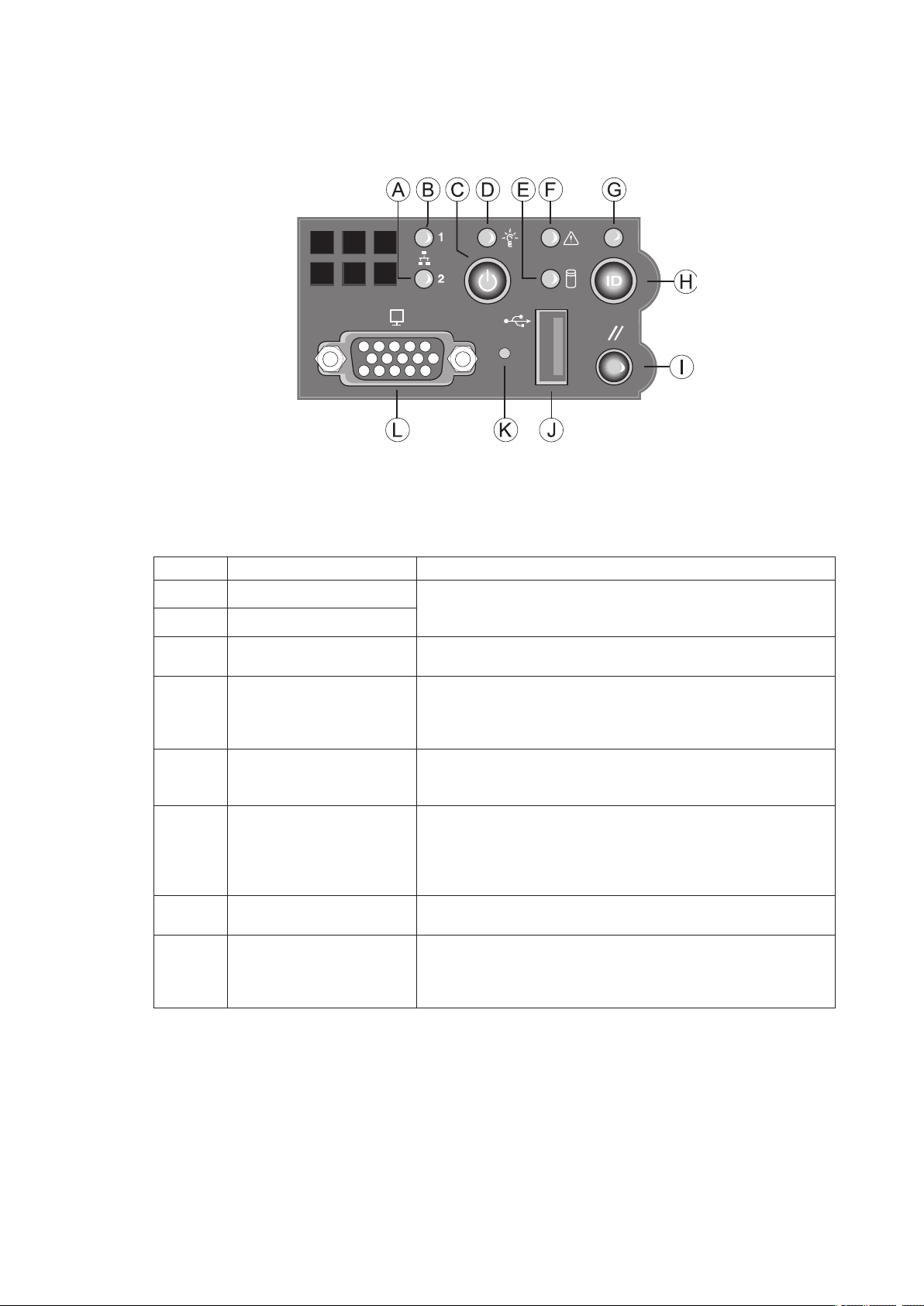
The diagram below shows the features available on the Standard Control Panel. The Standard Control
Panel is one of two required control options that can be selected. The other option is the Local Control
Panel.
a
Figure 2. Standard Control Panel
Table 2. Standard Control Panel Features
Callout Feature Function
A NIC 2 activity LED Continuous green light indicates a link between the system
B NIC 1 activity LED
C Power/Sleep button Toggles the system power on/off. Sleep button for ACPI
D Power/Sleep LED Continuous green light indicates the system has power
E Hard disk drive activity
LED
F System Fault LED Solid green indicates normal operation
G System Identification LED Solid blue indicates system identification is active
H System Identification
button
and the network to which it is connected.
Blinking green light indicates network activity.
compatible operating systems.
applied to it. Blinking green indicates the system is in S1
sleep state.
No light indicates the power is off / is in ACPI S4 or S5 state.
Random blinking green light indicates hard disk drive activity
(SCSI or SATA).
No light indicates no hard disk drive activity.
Blinking green indicates degraded performance
Solid amber indicates a critical or non-recoverable condition
Blinking amber indicates a non-critical condition
No light indicates POST is running or the system is off.
No light indicates system identification is not activated
Toggles the front panel ID LED and the baseboard ID LED
on and off. The baseboard LED is visible from the rear of the
chassis and allows you to locate the server from the rear of a
rack of systems.
(Continued)
9MAXDATA Server PLATINUM 2200 IR M5

Table 2. Standard Control Panel Features (Continued)
I Reset button Reboots and initializes the system.
J USB 2.0 port Allows you to attach a USB component to the front of the
chassis.
K NMI button Puts the server in a halt-state for diagnostic purposes.
L Video port Allows you to attach a video monitor to the front of the
chassis. The front and rear video ports cannot be used at
the same time.
Descriptions of the front panel LEDs are listed in the following table.
Table 3. Front Panel LED Description
LED Name Color Condition Description
Power/Sleep LED Green
Green
Status Green
Green
Amber ON Critical alarm: Critical power module failure, critical fan
Amber BLINK Non-critical failure: Redundant fan failure, redundant power
Hard Drive
Activity
NIC 1 Activity Green
NIC 2 Activity Green
ID LED (rack
only)
Green
Amber ON Fault
Green
Green
Blue BLINK Server identification; Toggled by ID button or software
ON Power On
BLINK Standby/Sleep (S1)
OFF Off (also Sleep S4)
ON System Ready
BLINK System ready, but degraded: some CPU fault, DIMM killed
failure, voltage (power supply), voltage and thermal fault
failure, non-critical power and voltage
OFF System not ready: Post error / NMI event / PCI or terminator
missing
BLINK Hard drive activity
OFF No activity
ON Linked
BLINK LAN activity
OFF Idle
ON Linked
BLINK LAN activity
OFF Idle
OFF Server identification; Toggled by ID button or software
10 Setting up the System
2 Server Board Features
This chapter briefly describes the main features of the MAXDATA PLATINUM Server Board. This
chapter provides a list of the server board features, and diagrams showing the location of important
components and connections on the server board.
Table 4 summarizes the major features of the server board.
Table 4. Server Board Features
Feature Description
®
Processors Support for up to two Intel
and frequencies starting at 2.8 GHz.
Memory Memory mirroring and memory sparing options Six DIMM slots supporting DDR
266 MHz or DDR 333 MHz memory
Chipset Intel® E7520 chipset, including:
• E7520 MCH
I/O Control
• PXH
• Intel
External connections:
®
82801ER I/O Controller Hub 5-R (ICH-5R)
• Stacked PS/2 ports for keyboard and mouse
• RJ45 Serial B port
• Two RJ45 NIC connectors for 10/100/1000 Mbps connections
• Two USB 2.0 ports
• U320 high-density 80-pin SCSI connector (channel B)
Internal connections:
• Two USB port headers, each of which supports two USB 2.0 ports
• One DH10 Serial A header
• One Ultra320 80-pin SCSI connector (Channel A)
• Two SATA-150 connectors with integrated RAID 0/1 support
• One ATA-100 connector
• SSI-compliant 34-pin, high-density 100-pin, and alternate 50-pin control panel
headers
®
• Intel
Management Module 120-pin connector, supporting the optional
Professional and Advanced server management modules
Add-in Card • One low-profile riser slot that supports a riser card capable of supporting upto
three low-profile PCI-X 66 / 100 MHz add-in cards.
• One full-height riser slot, utilizing Intel® Adaptive Slot technology. Capable of
supporting riser cards that follow either PCI-X or PCI-Express® specifications.
The riser cards can support upto three full-height, full-length PCI-X 66 /
100 MHz, PCI-X 133, or PCI-Express
used.
®
Video On-board ATI
RAGE XL video controller with 8 MB SDRAM
Xeon™ Processors with an 800 MHz front side bus
®
add-in cards, depending on the riser card
(Continued)
11MAXDATA Server PLATINUM 2200 IR M5

Table 4. Server Board Features (Continued)
Hard Drive, Optical
Drive, and Floppy
Drive
Floppy Support:
• Single Floppy channel accessed through either of two connectors. When
integrated with either the SATA or SCSI backplanes in the MAXDATA
PLATINUM 1500 IR or 2200 IR, the floppy controller signals are routed
through the 100-pin flex cable. Other server configurations can use the legacy
24-pin connector. Use of both interfaces in a common server configuration is
not supported.
Ultra ATA/100 support:
• Two IDE channels, each capable of supporting up to two drives. The primary
channel routes through a 100-pin flex cable to the backplane providing Optical
Drive support.
SATA support:
• Two SATA ports
• RAID level 0/1 support
SCSI support:
• Dual-channel LSI Logic
- Implements LSI Logic
- Supports LSI Logic
®
53C1030 Ultra320 SCSI controller
®
Fusion-MPT architecture
®
Integrated Mirroring and Striping technology
• Zero-channel RAID supporting the RUBI-2 specification
LAN Dual Intel® 82546GB 10/100/1000 NICs
Fans • Two 3-pin SSI compliant single speed processor fan connectors
• One 3-pin system fan connector with fan speed control.
• One 20-pin fan connector providing fan speed control and monitoring for
system fans in the MAXDATA PLATINUM 1500 IR and 2200 IR
Server
Management /
Diagnostics
• On-board Platform Instrumentation using the National Semiconductor
PC87431M mini-Baseboard Management Controller (mBMC) (Default).
• Support for optional Intel
®
Management Module - Advanced Edition or
Professional Edition
• Support for Intel® Server Management 8.x
®
• Intel
Light-Guided Diagnostics on all field replaceable units (FRUs)
12 Server Board Features
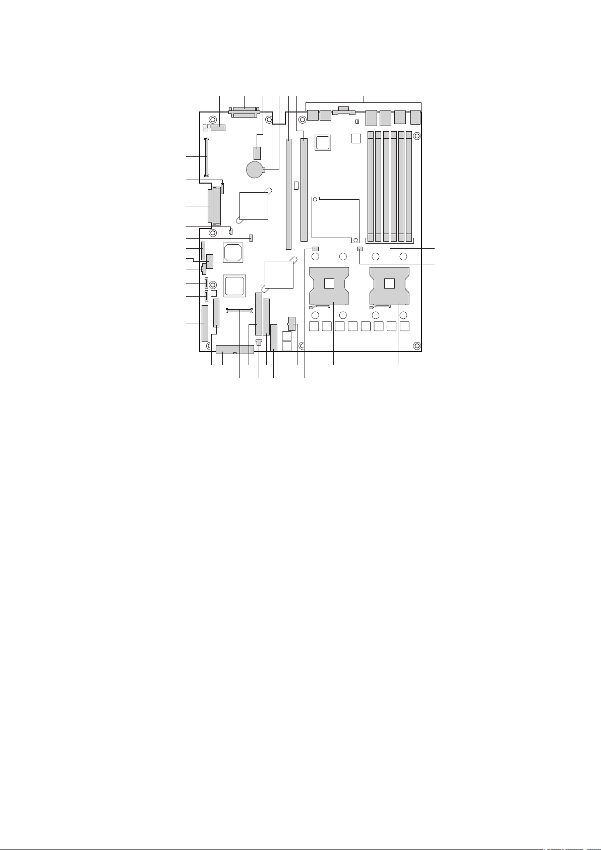
Connector and Header Locations
TP00757
A C DB E F G
H
I
JK
R
M
LN
ST
EE
CC
X
U
V
W
Z
Y
AA
DD
BB
QPO
a
Figure 3. Server Board Connector and Component Locations
A. Serial Port A L. Processor 2 fan header W. SATA port 2
SCSI Channel B M. +12V processor power X. Power supply signal cable
B.
C. 8-pin OEM connector N. Fan board connector Y. USB header (DH-10)
D. Battery O.
E. Full-height riser slot P. System fan 3-pin header AA. IPMB connector
F. Low-profile riser slot
G. Back panel I/O ports
H. DIMM sockets S. 24-pin SSI power connector DD. ICMB connector
I. Processor 1 fan header T. 50-pin control panel connector EE. 120-pin connector for optional
J. Processor socket 1 U.
K. Processor socket 2 V. SATA port 1
Floppy connector Z. USB header (1 x 10)
Q. Secondary IDE channel BB. IDE power connector
R. Control panel 100-pin
connector
34-pin SSI control panel
connector
CC. SCSI channel A
Intel® Management Module
13MAXDATA Server PLATINUM 2200 IR M5
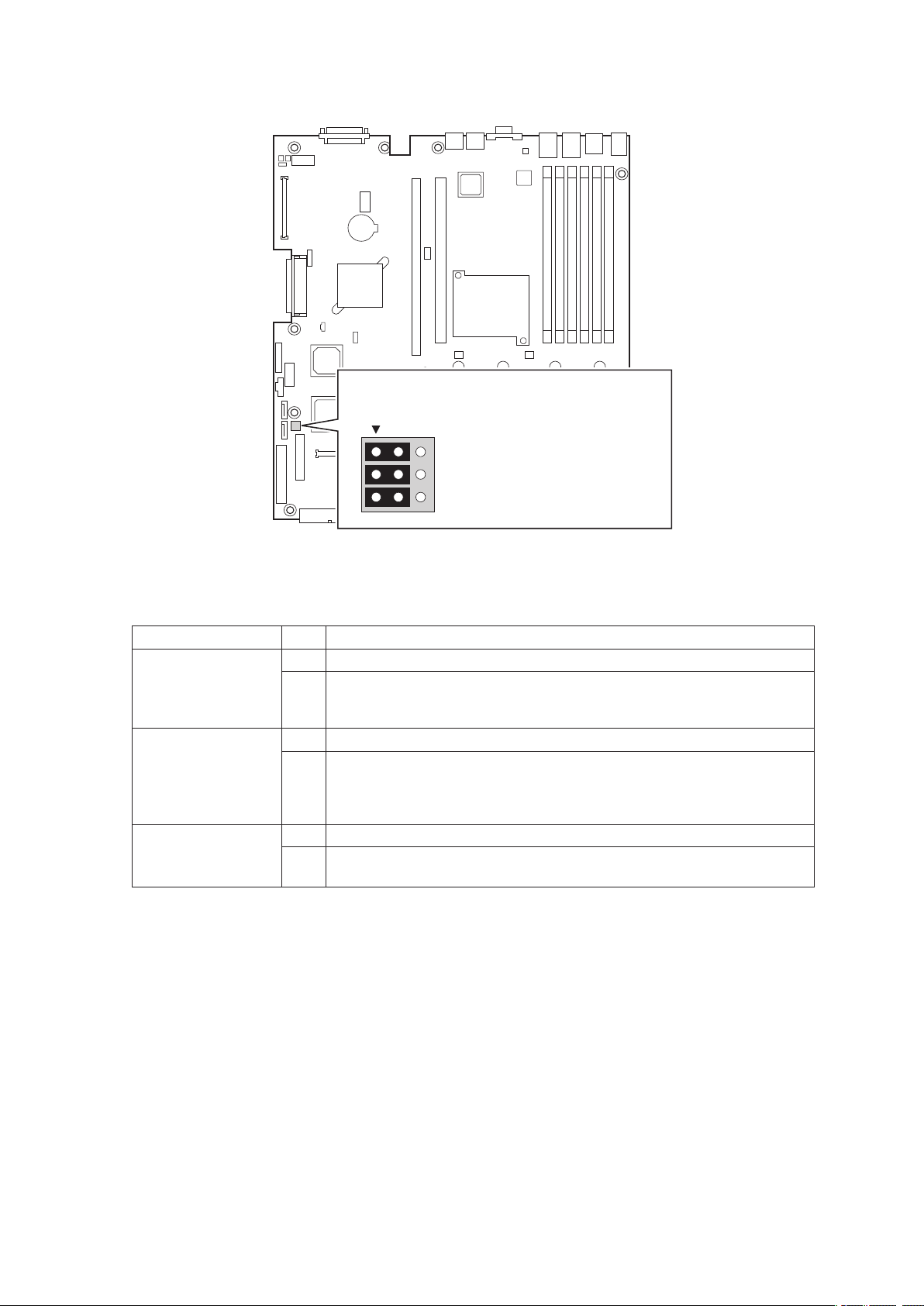
Configuration Jumpers
TP00759
3
2
C1-C2: CMOS Clear by BMC
1-2: Default setting for each jumper set
C2-C3: CMOS Clear Force Erase
B1-B2: Recovery Boot Disable (Normal Boot)
B2-B3: Recovery Boot Enable
A1-A2: Password Clear Protect
A2-A3: Password Clear Erase
A
B
C
a
Figure 4. Configuration Jumper Locations
Table 5. Configuration Jumper
Jumper Name Pins What happens at system reset…
Password Clear (line
“A” in figure above)
1 - 2 These pins should be jumpered for normal system operation.
2 - 3 If these pins are jumpered, administrator and user passwords will be
cleared on the next reset. These pins should not be jumpered for normal
operation.
Recovery Boot (line
“B” in figure above)
1 - 2 These pins should be jumpered for normal system operation.
2 - 3 If these pins are jumpered, the system will attempt to recover the BIOS
by loading the BIOS code into the flash device from a floppy disk. This
jumper is typically used when the BIOS has become corrupted. These
pins should not be jumpered for normal operation.
CMOS Clear (line
“C” in figure above)
1 - 2 These pins should be jumpered for normal system operation.
2 - 3 If these pins are jumpered, the CMOS settings will be cleared on the
next reset. These pins should not be jumpered for normal operation.
14 Server Board Features

Hardware Requirements
Processor
One or two Intel® Xeon™ Processors with an 800 MHz front side bus must be installed. Processor
frequencies form 2.8 GHz to 3.6 GHz are supported.
Memory
The server board provides six DIMM sockets across two channels, Channel A and Channel B. Channel
A consists of DIMM sockets 1A, 2A, and 3A. Channel B consists of DIMM sockets 1B, 2B, and 3B.
If six DIMMs are installed, the following maximum capacitites are possible:
• For DDR266 DIMMs: Maximum capacity of 24 GB
• For DDR333 DIMMs: Maximum capacity of 16 GB
A minimum of one 256 MB DIMM is required in DIMM socket 1A or 1B. This uses single-channel
interleave. However, for dual-channel interleave, providing optimum performance, a minimum of two
DIMMs should be installed in DIMM sockets 1A and 1B. Except for the option of installing a single
DIMM in socket 1A or 1B, DIMMs must be installed in pairs and populated as follows:
• DIMM 1A and DIMM 1B: Populate these two sockets together first
• DIMM 2A and DIMM 2B: Populate these sockets in addition to DIMM 1A and DIMM 2A if four
DIMMs are to be used.
• DIMM 3A and DIMM 3B: Populate these sockets after DIMM 1A, DIMM 1B, DIMM 2A, and
DIMM 2B have been populated.
DIMMs must meet the following requirements:
• Use only registered DDR DIMM modules
• DDR266 and DDR333 memory can be mixed on the server board, but when mixing DIMM
types, DDR333 memory will be treated as DDR266.
• Use only DIMMs with DIMM organization of x72 ECC
• Use only DIMMs with the capacities outlined in the following table can be used
Table 6. DIMM Module Memory Capacity Support
SDRAM Parts, SDRAM
Technology
X8, single row 128 MB 256 MB 512 MB 1 GB
X8, double row 256 MB 512 MB 1 GB 2 GB
X4, single row 256 MB 512 MB 1 GB 2 GB
X4, stacked, double row 512 MB
128 MB 256 MB 512 MB 1 GB
1 GB 2 GB 4 GB
NOTE
When using Dual Rank (Double Row) DDR-333 DIMM technologies, a maximum of four loads per
memory channel is supported. When all DIMMs used in the system match either of these technologies,
a maximum of four DIMMs can be populated.
In determining your memory requirements, the need for memory sparing or memory mirroring must
be considered.
15MAXDATA Server PLATINUM 2200 IR M5
 Loading...