

Page 1

Avid Liquid Chrome HD
Installation
English
Page 2

2
Page 3

Avid Liquid Chrome HD
Installation
English
Deutsch
Français
.................................... page
............................... Seite 91
.............................. page 185
1
3
Page 4

4
Page 5

© 2006 Pinnacle Systems GmbH. All rights reserved.
March 2006 / Pinnacle Systems Documentation, Munich, Germany
liquid.documentation@pinnaclesys.com
Copyright and Protective Rights
This manual or the software described herein, in whole or in part, may not be reproduced, translated or reduced to
any machine readable form without prior written approval from Pinnacle Systems GmbH.
Pinnacle Systems GmbH AG PROVIDES NO WARRANTY WITH REGARD TO THIS MANUAL, THE SOFT-
WARE OR OTHER INFORMATION CONTAINED HEREIN AND HEREBY EXPRESSLY DISCLAIMS ANY
IMPLIED WARRANTIES OF MERCHANTABILITY OR FITNESS FOR ANY PARTICULAR PURPOSE WITH
REGARD TO THIS MANUAL, THE SOFTWARE OR SUCH OTHER INFORMATION. IN NO EVENT SHALL
INNACLE SYSTEMS GMBH BE LIABLE FOR ANY INCIDENTAL, CONSEQUENTIAL OR SPECIAL DAMAGES,
P
WHETHER BASED ON TORT, CONTRACT, OR OTHERWISE, ARISING OUT OF OR IN CONNECTION
WITH THIS MANUAL, THE SOFTWARE OR OTHER INFORMATION CONTAINED HEREIN OR THE USE
THEREOF.
Pinnacle Systems GmbH reserves the right to make any modification to this manual or the information contained
herein at any time without notice.
The software described herein may also be governed by the terms of a separate user license agreement.
YOU MAY USE THIS SOFTWARE TO ASSIST YOU IN COPYING MATERIAL IN WHICH YOU OWN THE
COPYRIGHT OR HAVE OBTAINED PERMISSION TO COPY FROM THE COPYRIGHT OWNER. IF YOU DO
NOT OWN THE COPYRIGHT OR YOU HAVE NOT OBTAINED PERMISSION TO COPY FROM THE COPY-
RIGHT OWNER, YOU MAY BE VIOLATING COPYRIGHT LAW AND YOU MAY BE SUBJECT TO CLAIMS
FOR DAMAGES AND/OR CRIMINAL PENALTIES.
5
Page 6

Trademarks
© Avid Liquid,
Avid Liquid PRO
Pinnacle Systems and the Pinnacle Systems logo are registered trademarks of Pinnacle Systems, Inc.
Sony, ClipLink, DV, DVCAM, Digital Betacam, Betacam SP, Betacam SX, Hi8, Video8, HDCAM, D2, Digital8, D8,
i.LINK and the i.LINK logo are trademarks of Sony Corporation; D3, D5, Panasonic and DVCPRO are trademarks
of Matsushita Electric Industrial Company; D9, Digital-S and D-VHS are trademarks of JVC; Dolby A, B, C, SR
and Dolby Surround are trademarks of Dolby Laboratories; Manufactured under license from Dolby Laboratories.
© 1992-2003 Dolby Laboratories. All rights reserved. Dolby is a trademark of Dolby Laboratories; OMF
Media Log are trademarks of Avid Technology, Inc.; Media Cleaner is trademark of Terran Interactive - a subsid-
iary of Media 100, Inc.; FaderMaster Pro is trademark of JL Cooper - a department of Sound Technology; Java is
trademark of Sun Microsystems; Photo CD is trademark of Eastman Kodak Company; Acrobat Reader and Adobe
AfterEffects are trademarks of Adobe Systems, Inc.; Microsoft
MS-DOS
ness Machines Corporation; Intel
mark of Matrox Electronic Systems Ltd.
Parts of this product have been produced using LEADTOOLS
RIGHTS RESERVED. Parts of this product are based on the work of the independent JPEG-Group.
All other nationally and internationally recognized trademarks and trade names are hereby acknowledged and are
the property of their respective owners.
Avid Liquid Chrome HD, Avid Liquid Blue, Avid Liquid
are logos and trademarks of Pinnacle Systems GmbH and Pinnacle Systems, Inc.
, Avid,
and Intellimouse are trademarks of Microsoft Corporation; VGA is trademark of International Busi-
and Pentium are trademarks of Intel Corporation; Matrox DigiSuite is trade-
, Windows XP
, Win dows
, Windows 2000,
©1991-2000, LEAD Technologies Inc. ALL
,
6
Page 7

Contents
Chapter 1 Hardware and Software Installation.................................................... 9
Safety Hints........................................................................................... 10
Additional Instructions..................................................................... 10
Safety Standards............................................................................. 10
Implementation in Accordance with Intended Use.......................... 10
Symbols and Conventions............................................................... 11
Safety Instructions for Initial Startup ............................................... 11
Safety when Operating.................................................................... 11
Delivery Package.................................................................................. 12
PC System Recommendations............................................................. 13
The Avid Liquid Chrome HD PCI Board................................................ 14
Installing the Avid Liquid Chrome HD Board................................... 15
Avid Liquid Chrome HD Breakout Boxes .............................................. 17
Pro HD Digital Breakout Box........................................................... 18
Combo Breakout Box (SD/HD)........................................................ 21
Pro Digital Plus Breakout Box......................................................... 23
Connecting The Control Panel (Jog/Shuttle)......................................... 26
Software Setup ..................................................................................... 27
Install the Avi d Li qu id Ch ro me HD Software................................... 27
Graphics Cards Settings................................................................. 28
Turn Off Windows and BIOS Power Management Options............. 28
Internet Explorer ............................................................................. 28
Adobe Acrobat Reader.................................................................... 28
Launching Avid Liquid Chrome HD................................................. 28
Genlock (Reference) and Device Remote Control (RS 422) Settings... 29
Genlock Routing (Reference Signal)............................................... 29
Device (Remote) Control via RS 422.............................................. 31
Page 8

Technical Specifications................................................. .. ... .................. 32
Avid Liquid Chrome HD Card.......................................................... 33
Pro HD Digital Breakout Box........................................................... 34
Combo SD/HD Breakout Box.......................................................... 36
Pro Digital Plus Breakout Box ......................................................... 42
Chapter 2 Site Settings........................................................................................ 45
Player Settings...................................................................................... 47
How to Change Para meters............................................................ 48
Settings Tab .............................. ................................. ... .................. 49
Connections Tab ............................................................................. 58
System Settings.................................................................................... 62
Changing Parameters..................................................................... 62
General Tab..................................................................................... 63
Inputs/Outputs Tab....................... .. ................................................. 64
FX Editors Settings............................................... ................................ 68
Render Quality Tab ......................................................................... 68
Preview Quality Tab......................................................................... 68
System Tab ..................................................................................... 69
Advanced Settings.......................................................................... 69
Plug-In Settings..................................................................................... 70
Avid Liquid Chrome HD Calibration Cont rols........................................ 71
Calibration Control Settings............................................................ 73
Standard Tab................................................................. ... ............... 79
Other Special Features of Avid Liquid Chrome HD............................... 80
For HDV and DV formats................................................................. 86
Index..................................................................................................... 89
8
Page 9

Chapter
Hardware and Software Installation
1
Page 10

Chapter 1 Hardware and Software Installation
Safety Hints
This manual is an important component of
available in the vicinity of
working with or managing the system.
Additional Instructions
The system operator shall add to the manual any additional operating instructions demanded by
national regulations regarding prevention of accidents and environmental protection, including information on obligations to supervise and register with regard to special conditions, for example with reference to organization of work, work procedures and the persons engaged to perform the work.
Also to be observed, in addition to the regulations in the manual and the currently binding regulations
on accident prevention in the country concerned and at the site of implementation, are the approved special technical regulations regarding safe and proper operation on and with the equipment concerned.
Safety Standards
The
Avid Liquid Chrome HD
tested to comply with applicable standards, state-of-the-art technology and recognized safety regulations.
For customers in Europe
Conformance to European guidelines and standards is confirmed by CE certification and the CE declaration of conformity.
Avid Liquid Chrome HD
Avid Liquid Chrome HD
editing system and its components were developed, produced and
. It should be permanently
, and is to be read and applied by every person
For customers in the USA
The system was tested to comply with “FCC standards for home and office use”.
For more information on CE and FCC Declarations, contact Avid Technology, Inc.
Implementation in Accordance with Intended Use
Avid Liquid Chrome HD
Any other use shall not be deemed intended use. Any damages resulting shall be the sole responsibility of
the user/system operator.
10
is intended exclusively for video and audio editing.
Page 11
Symbols and Conventions
Symbols Identifying Special Texts
Caution
Calls the reader’s attention to especially “dangerous” actions, i.e. actions that could lead to a loss of data.
Note
Calls the reader’s attention to important information and practical tips or workarounds.
Safety Instructions for Initial Startup
Danger
To prevent fire or shock hazard, do not expose the unit to rain or moisture.
If a solid object or liquid gets into the inside of the system, disconnect the system from the power supply
and inform Customer Service immediately.
Do not install the unit with the
radiators or hot air ducts, or in a place subject to direct sunlight, excessive dust, mechanical vibration or
shock.
Avid Liquid Chrome HD
Safety Hints
interface card near heat sources such as
Special Hazards
Danger
Risk of electric shock and destruction of
All local grounding and lightning protection regulations are to be observed for the system.
Safety when Operating
Warning
This is a Class A device that can under certain circumstances cause radio interference in residential areas.
The device operator is required to take suitable countermeasures!
In the case of radio interference, switch the computer system off immediately and disconnect the power
supply cord. In doing so always pull on the connector and never on the cable. Troubleshoot immediately.
Avid Liquid Chrome HD
system components.
11
Page 12

Chapter 1 Hardware and Software Installation
Delivery Package
Avid Liquid Chrome HD
Avid Liquid application software (CD or DVD-ROM)
Installation and Reference Manual (printed)
Third party software
and:
Avid Liquid Chrome HD
Cables
PCI board
breakout box (one or two out of three available types)
12
Page 13

PC System Recommendations
We recommend that you use a certified Avid Technology, Inc. workstation. This is because the throughput requirements for multiple simultaneous video streams plus graphics and audio are extremely high.
As a result, system hardware requirements are equally high.
high-end workstation capable of handling this level of throughput.
Avid Technology, Inc. has certified only a few specific configurations so these and other criteria can be
precisely optimized for the highest possible throughput in a real-time video environment. These settings
are so interrelated and specific to each configuration that it is exceptionally difficult for Avid Technology,
Inc. to support systems that we do not physically have in Technical Support.
Although you may have had a successful experience in configuring a video system yourself, we do not
encourage attempting to do so with a
your Avid Technology, Inc. Authorized Reseller to configure a system for you. For a list of Authorized
Resellers and certified
vices section of the Avid Technology, Inc. web site at www.avid.com
Avid Liquid Chrome HD
Avid Liquid Chrome HD
PC System Recommendations
Avid Liquid Chrome HD
. It is a better choice to rely upon
system configurations, see the Products & Ser-
requires a
13
Page 14
Chapter 1 Hardware and Software Installation
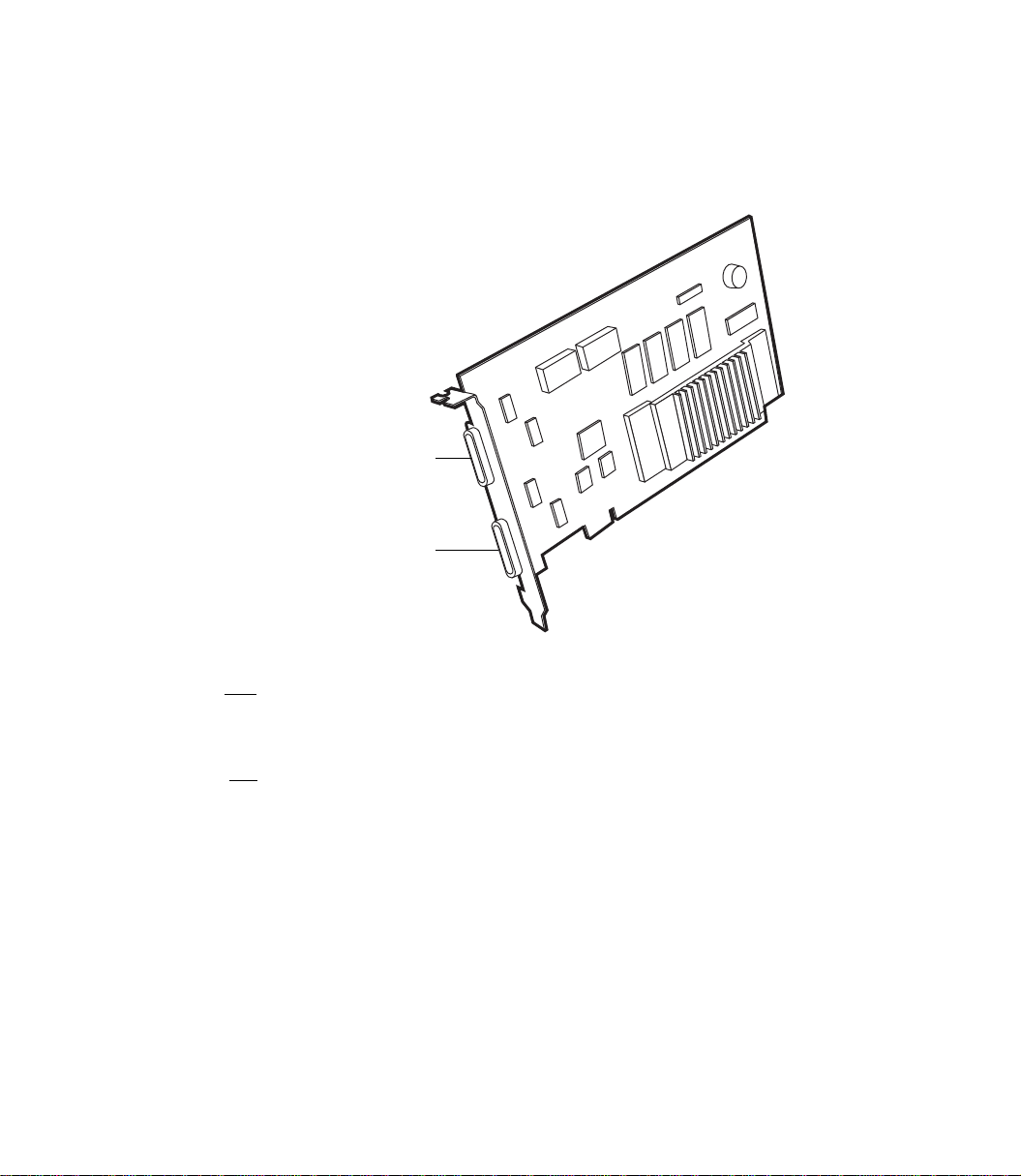
The Avid Liquid Chrome HD PCI Board
This section describes how to install the
Connector #2
HD and SD
Connector #1
SD only
Avid Liquid Chrome HD board sample illustration (actual card design may differ)
Avid Liquid Chrome HD
board in your computer system.
1 SD only Digital Tether 36-pin connector -
This connector is reserved for SD boxes (NTSC/PAL, analog and/or digital). HD video cannot be
transmitted via this connector.
14
2 HD and SD Digital Tether 36-pin connector -
This connector accepts input from and provides output to a SD analog or digital or a digital HD
breakout box. The Pro HD breakout box must be connected to this connector.
The Combo SD/HD box has two Digital Tether connectors, one for SD and one for HD.
Page 15

Installing the Avid Liquid Chrome HD Board
Overview Of Hardware Installation
The Avid Liquid Chrome HD PCI Board
Complete hardware installation of the
doing the following:
Avid Liquid Chrome HD
board can be accomplished by
1 Install board into the computer
2 Attach one or two Breakout Box(es) to the board
3 Connect input and output devices your Breakout Box
Details for each of the items listed above can be found in this chapter.
Card Installation Procedure
These are general-purpose installation instructions. Since a computer can come in different design configuration styles (such as the “tower” design), you should refer to the owner’s manual of your computer
for additional information on installing cards. You should also refer to the “Read Me” files provided with
Avid Liquid Chrome HD
the
1. Turn off the computer and monitor
Unplug the computer and disconnect any communication cables from the rear of the computer. Unplugging the power cord and cables helps to ensure that no power is running on the motherboard, which
reduces the risk of damage to your equipment and the PCI card.
2. Remove the cover from the computer
Check the owner’s manual for instructions on how to remove the cover.
software.
3. Discharge static electricity that you may
have on your clothes or body
If available, use an Anti-Static Wrist Strap. Also, touch the metal part of the power supply to discharge
any static electric charge that you might be carrying.
15
Page 16
Chapter 1 Hardware and Software Installation
4. Prepare an expansion slot
Locate an empty PCI slot and remove the metal slot cover at the back of the computer’s expansion slot
area. Make sure the slot can accommodate the full length and width of the board, and that there are no
obstructions.
The PCI slot you need is of the 64 Bit bus type. These are usually longer than the 32 bit slots. If you cannot easily identify the 64-bit slot, refer to the computer mainboard instruction manual.
5. Remove the board from its antistatic bag
Handle the card by its edges and by its metal bracket. Avoid touching the connector pins on the bottom
of the card.
6. Insert the board into the expansion slot
With the bracket toward the open access port, align the connector on the bottom of the card directly over
the slot you’ve chosen. Then push down and gently rock the card lengthwise until the card is firmly
seated. The board may need to be “seated” twice. When pushed into the slot, the board will catch as if it
were in place – gently continue to exert pressure until the board “seats” again or until you see that the
board is completely installed.
Don’t force the card. If there is resistance, remove the card and try again.
16
7. Connect Breakout Box(es) to the board
Connect the cable from the back of your Breakout Box to the output connector on the bracket of the
Avid Liquid Chrome HD
tors, as described in “The Avid Liquid Chrome HD PCI Board” on page 14.
The HD box must be attached to the connector that sits closer to the bracket screw. SD boxes can be
attached to any of the two connectors.
We recommend that you do not disconnect or reconnect the Breakout Box cable from or to the card
while the computer is powered up.
board. Please attach HD and SD boxes to their corresponding connec-
Page 17

Avid Liquid Chro me HD Breakout Boxes
Avid Liquid Chrome HD Breakout Boxes
Avid Liquid Chrome HD
provides a set of video, audio and auxiliary inputs and outputs as well as interfaces to remote control
players and recorders. The software recognizes the connected Breakout Box automatically.
To switch boxes, shut down the computer, plug in the new box and power up the computer. You don’t
have to re-install the software. The software recognizes the new box automatically.
Here is an overview of Breakout Boxes specifically available for
was designed to run with a variety of Breakout Boxes. Each Breakout Box
Avid Liquid Chrome HD
:
Pro HD Digital Breakout Box (HD), page 18
Combo Breakout Box (SD and HD) page 21
Pro Digital Plus Breakout Box (SD), page 23
You may also use the
Avid Liquid PRO Box
, which connects to the USB2 port of the computer.
17
Page 18

Chapter 1 Hardware and Software Installation
Pro HD Digital Breakout Box
The Pro HD Digital Breakout Box inputs uncompressed serial digital (SDI) HD video to and outputs
uncompressed serial digital HD video from the
tal Breakout Box connects to the card via the Digital Tether Cable. The supported SDI signal for input
and output is SMPTE 292M, SMPTE 274M (1080P format) and SMPTE 296M (720P format).
You must connect the HD box to Digital Tether connector #2 (the one closer to the bracket screw; see
“The Avid Liquid Chrome HD PCI Board” on page 14.)
For its technical specifications, see “Pro HD Digital Breakout Box” on page 34.
Connecting Audio/Video I/O Devices
To Pro HD Digital Breakout Box
From your originating input source component serial digital equipment, attach the HD-SDI output connection of the equipment (e.g., Camcorder, VCR, VTR, etc.) to the BNC “IN” connection of the Pro HD
Digital Breakout Box.
Then attach the BNC connection for “Out” on the Pro Digital Breakout Box to the input connection on
the receiving output signal device.
The Pro HD Digital Breakout Box always uses the video input as reference source. Video input must be
connected at all times for proper operation of the Pro Digital box. See also “Genlock Routing (Reference
Signal)” on page 29.
Avid Liquid Chrome HD
card. This Pro HD Digi-
18
Avoid disconnecting an active SDI source while Avid Liquid is running, particularly when the Logging
To o l is open.
Page 19
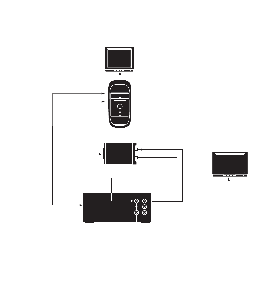
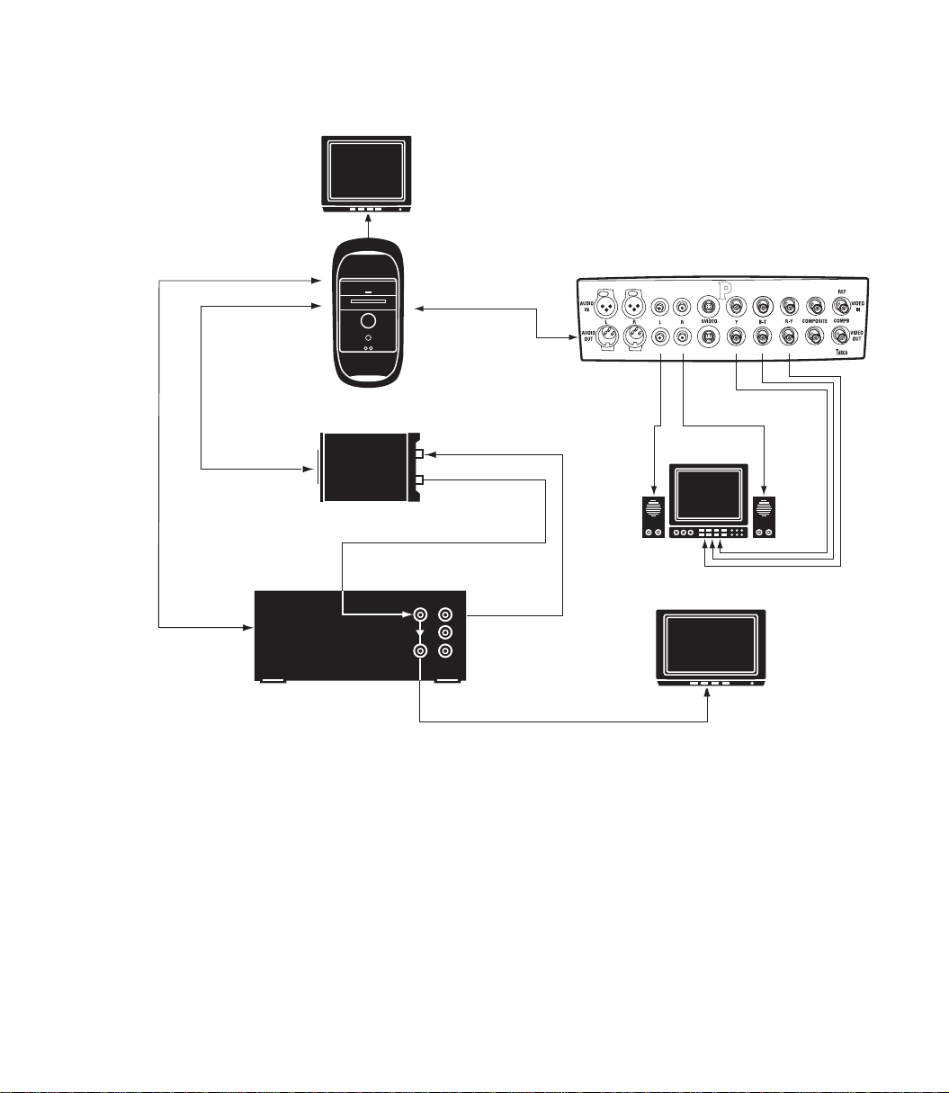
Please refer to the following two wiring diagrams:
Monitor
RS-422 Serial Deck Control
Digital Tether Cable
Computer CPU
Avid Liquid Chrome HD Breakout Boxes
Remote In
IN
OUT
Pro HD Digital Breakout Option
OUTIN
loop
HD Compatible Tape Deck
Capture and playback for High Definition Video
IN
HD Compatible Monitor
OUT
1
2
3
19
Page 20
Chapter 1 Hardware and Software Installation
Monitor
RS-422 Serial Deck Control
Digital Tether Cable
Digital Tether
Remote In
Computer CPU
IN
OUT
IN
Analog Video Monitor
Component Video Out
RCA Audio
OUT
Pro HD Digital Breakout Option
HD Compatible Monitor
loop
OUTIN
1
2
3
HD Compatible Tape Deck
Realtime down convert of High Definition video (realtime 3:2 pull down)
Component Video In
20
Page 21
Combo Breakout Box (SD/HD)
The Combo SD/HD box offers a full range of analog and digital standard- and high-definition connectivity in a professional rack-mounted breakout box.
The box also supports AES/EBU audio, S/PDIF audio, TDIF audio, XLR balanced audio, RCA unbalanced audio, Reference In (synchronized or genlocked), and Word Clock.
This box is connected to the
connectors (SD and HD; see “The Avid Liquid Chrome HD PCI Board” on page 14). For technical speci-
fications, see page 36.
Avid Liquid Chrome HD
Avid Liquid Chrome HD Breakout Boxes
PCI board with both of its Digital Tether
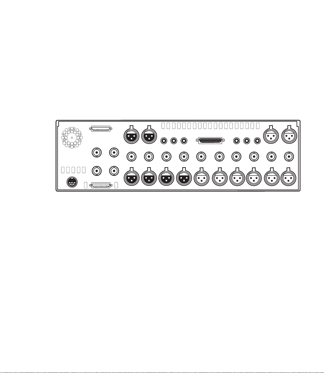
1/2 IN 3/4IN
S/PDIF OUTR OUT
L OUTTDIF(1-8)R INL INS/PDIF IN
CV IN Y IN Pb IN Pr IN SDI IN
1 IN 2 IN 3 IN 4 IN 1 OUT 2 OUT 3 OUT 4 OUT 5 OUT 6 OUT
SDI OUT Y OUT Pb OUT Pr OUT CV OUT
Power
SD DIGITAL TETHER
WORD CLK OUT
HD DIGITAL TETHER
REFERENCE IN
HD-SDI IN HD-SDI OUT
The back panel of the Combo SD/HD breakout box
The input and output connections for the Combo SD/HD Breakout Box are defined as follows:
HD-SDI -
Connect HD-SDI signals to the BNC connectors labeled „HD-SDI“.
SDI -
If you are using a Serial Digital Interface (SDI) as your input or output source, use the BNC connector labeled “SDI”. SDI for this breakout box is an uncompressed standard definition signal.
Component -
The BNC connectors labeled “Y,” “Pb” and “Pr” are used for Betacam and Betacam-J component
input and output. If a Betacam format is going to be used, all three of the BNC connectors for
input or output must be used for a complete betacam signal. “
COMPOSITE (CV) -
If you are using a Composite Video input or output source, use the BNC connector labeled “CV“.
3/4 OUT1/2 OUT
XLR Audio -
There are four XLR connectors for balanced analog audio input, and six for output.
RCA Audio -
21
Page 22

Chapter 1 Hardware and Software Installation
The dual-channel RCA connectors are for unbalanced analog input and output audio. Use the
RCA connector labeled “L” for Left and “R” for right.
AES/EBU -
Digital audio inputs and outputs, 4 channels (1/2 and 3/4) via XLR.
S/PDIF -
Digital audio inputs and outputs, 2 channels via RCA (S
TDIF -
Digital audio inputs and outputs, 8 channels via 25-pin Sub-D connector. This connector is for
simultaneously transferring multiple channels of digital audio between multiple track machines
EAC Digital Interface Format protocol.
in the T
Wor d C lk Out -
This connector is used to synchronize two digital devices to operate at the exact same clock
speed. The Word Clock is a digital signal. Refer to the documentation provided with your digital
device for additional information.
Reference In -
A reference signal is used to provide a genlock source and subcarrier field ID for the video outputs. Refer to the documentation provided with the equipment you’re using for information on
locking the video signal to a common reference. See also “Genlock Routing (Reference Signal)” on
page 29.
ony/Philips Digital Interface protocol).
22
Page 23
Pro Digital Plus Breakout Box
The Pro Digital Plus Breakout Box inputs uncompressed standard definition Serial Digital Interface
(SDI) video to the
standard definition serial digital video from the
Plus fully supports AES/EBU audio and analog Composite Video and RCA unbalanced audio output to a
monitor.
For its technical specifications, see “Pro Digital Plus Breakout Box” on page 42.
Avid Liquid Chrome HD
Avid Liquid Chrome HD Breakout Boxes
board. This breakout box also outputs uncompressed
Avid Liquid Chrome HD
board. The Pro Digital
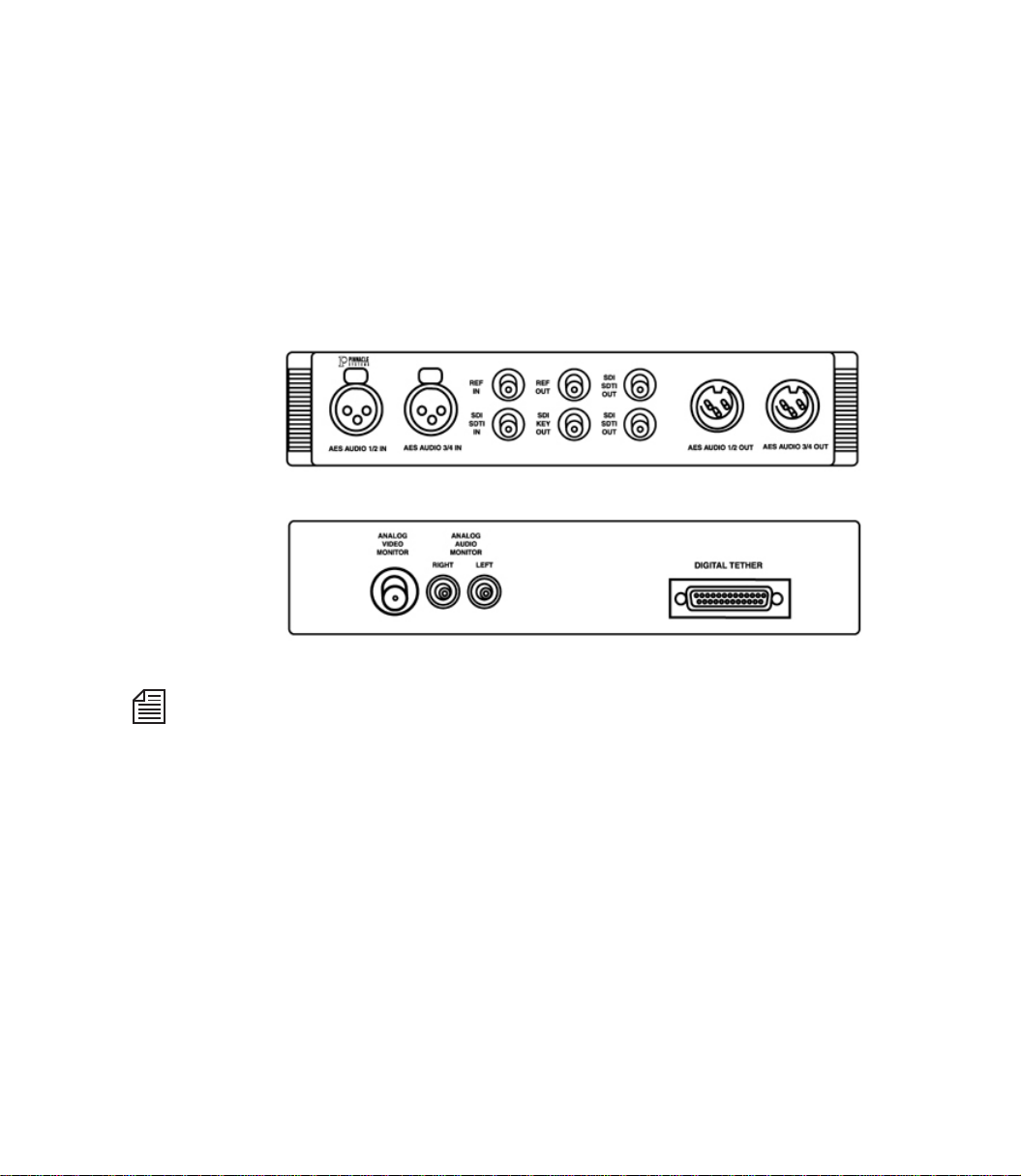
Front and back panel of the Pro Digital Plus Breakout Box
The Pro Digital Plus Breakout Box will also input and output standard definition compressed Serial Digital Transport Interface (SDTI) video, but this compressed format is not supported by the
Liquid Chrome HD
The Pro Digital Plus Breakout Box connects to the
Tet he r™ Cab le .
board.
Avid Liquid Chrome HD
Avid
board via the Digital
23
Page 24

Chapter 1 Hardware and Software Installation
Pro Digital Plus Breakout Box Input
And Output Connections
The input and output connections for the Pro Digital Plus Breakout Box are defined as follows:
AES Audio -
These connectors are used for transferring digital audio in the Audio Engineering Society (AES)
and European Broadcast Union (EBU) protocol. There are connectors for audio channels 1 and 2
(1/2) and audio channels 3 and 4 (3/4).
REF -
Reference (REF) is used to provide a genlock clock source and subcarrier field ID for the Serial
Digital Interface (SDI) video. If “REF In” is used, both it and the selected SDI/SDTI must be
locked together. “REF Out” is a buffered loop-through of “REF In.” Refer to the documentation
provided with the equipment you’re using for information on locking the video signal to a common reference.
See also “Genlock Routing (Reference Signal)” on page 29.
SDI SDTI -
If you are using a Serial Digital Interface (SDI) as your input or output source, use the BNC connector labeled “SDI SDTI.” SDI for this breakout box is an uncompressed standard definition signal.
24
SDI Key Out -
An SDI “Key” output signal is provided for application software that allows an 8-bit Alpha channel for image blending information. Making use of the SDI Key signal is a function of third party
applications designed to take advantage of this hardware feature.
Analog Video -
The BNC connector on the back of the Pro Digital Plus Breakout Box is for Composite Video
(CV) output to a video monitor.
Analog Audio -
The dual-channel RCA connectors on the back of the Pro Digital Plus Breakout Box are for line
level, unbalanced analog audio output to an audio monitor.
Page 25
Avid Liquid Chrome HD Breakout Boxes
Connecting Audio/Video Input And Recording Devices To
Pro Digital Plus Breakout Box
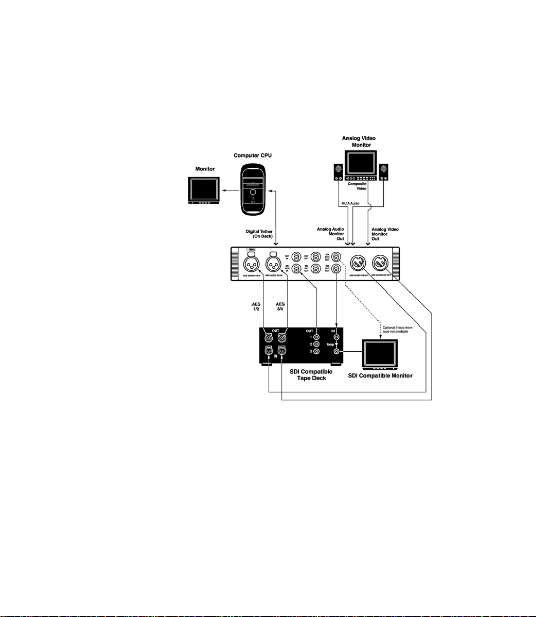
For an example connection diagram with the Pro Digital Plus Breakout Box, refer to this figure:
Pro Digital Plus sample cabling setup
25
Page 26

Chapter 1 Hardware and Software Installation
Connecting The Control Panel (Jog/Shuttle)
Avid Liquid Control
navigating the material already digitized. The jog/shuttle control knob is for quick and easy viewing and
processing of audio/video material in both linear and non-linear mode.
number of freely assignable keys for configuring it to suit your personal needs. A more detailed description on the keyboard layout and operation of
reference manual, chapter Customize, under “Customizing
Avid Liquid Control
tor. The port on
On initial installation of Avid Liquid:
Avid Liquid Control
is a control panel for remote control of the player/recorder connected and for
Avid Liquid Control
Avid Liquid Control
Avid Liquid Control
Control Panel for remote control of the player/recorder
is connected to the USB interface on the PC via the supplied cable and adap-
is an RJ-45 jack. Power is supplied via the USB port.
can be found in the Avid Liquid
”.
has a
1 Connect the Jog/Shuttle device to a USB port of the computer before you run the setup.
2 Check the “Jog/Shuttle” box in the setup dialog (if it is not already checked).
If you want to add the device to your existing setup:
1 Close Avid Liquid (if running).
2 Connect the Jog/Shuttle to a USB port of the computer.
3 From the Avid Liquid installation CD, run the USBJS.Setup.exe application.
(From the Windows Start menu select Run..., then use the Browse button to navigate to the CD
ROM drive and to search for the application. Once found, click OK.)
26
Page 27

Software Setup
This section provides information on the first steps you should take after installing the hardware.
Install the Avid Liquid Chrome HD Software
Avid Liquid must be installed from a Windows account with administrator privileges. This is required
for security reasons because the installation program loads device drivers into the operating system.
1 Exit all running applications.
Software Setup
2 Place the
computer.
Avid Liquid Chrome HD
installation disk into the DVD/CD-ROM drive of your
3 The installation program will automatically open.
If the installation program does not open, double click the DVD/CD
to open it, and then start the installation utility (search for a file named autoplay.exe or liq-
HD
uidchrome.HD.setup.exe, or similar).
The installation program will lead you through a number of screens asking you for information.
Simply provide the necessary information or press
ESC at any time to abort the installation. When the installation is complete, you must restart your
computer before using the application.
If you plan to install Avid Liquid over a existing Avid Liquid installation, use the Windows Control Panel
Add/Remove utility to remove the application. During uninstall a message will be displayed (warning of
shared files to be deleted). Select “Yes to all” and continue.
ENTER to accept the default. You may press
Avid Liquid Chrome
27
Page 28

Chapter 1 Hardware and Software Installation
Graphics Cards Settings
It is strongly recommended to set the display to 32 bit color depth mode (Windows Control Panel > Display Properties > Settings > Color).
In a dual monitor setup, we suggest to select a desktop view that positions the Source and Master Viewers
on the left (or „primary“) monitor
video.
: viewers on the right may cause dropped frames when playing back
Turn Off Windows and BIOS Power Management Options
All power management options, particularly sleep, hibernate and standby modes provided by Windows
OS or the computer’s BIOS should be turned off. Never enable the Windows Turn off hard disks option.
Check the the current settings in Windows Start menu > Settings > Control Panel Power Options and in
the BIOS.
Internet Explorer
Microsoft Internet Explorer 5.0 (or higher) is required for using the HTML Online Help.
Install it on the personal computer if it is not already installed with Windows.
Adobe Acrobat Reader
Adobe Acrobat Reader is required for viewing the Reference Manual online files (PDF).
Install it on the PC, if it isn’t already on your computer.
Launching Avid Liquid Chrome HD
To ru n
Avid Liquid Chrome HD
trator status).
28
, a user must log on with Windows power user status (or adminis-
Page 29

Genlock (Reference) and Device Remote Control (RS 422) Settings
Genlock (Reference) and Device Remote Contro l
(RS 422) Settings
After you have installed the software there are two more preconditions to establish: a correct synchronisation of your editing environment, and remote control of connected players and recorders.
Genlock Routing (Reference Signal)
There are two ways to set up a correct sync lock for
with house sync (reference signal provided by external sync generator)
without house sync (reference signal provided by video input)
A word on reference signals and genlocking: Most tape decks that are locked to an external reference signal display a warning when a reference problem occurs. This machine warning is passed on via the driver
and becomes visible in Avid Liquid’s Logging Tool and Record to Tape tool.
A missing or bad reference is always a severe problem because it can damage editing accuracy. What
actually happens depends much on the device. Some have a fallback mechanism that forces the machine
to rely on input (analog) video. Some machines allow you to switch off the reference warning, but then
be aware that editing accuracy may not be guaranteed anymore.
Avid Liquid Chrome HD
:
With House Sync
1 Connect reference signal generator to RefIn of tape deck.
2 Loop RefOut of tape deck and connect to RefIn of Breakout Box (Pro Digital Plus, Combo SD/
HD box).
3 Video Out of Breakout Box feeds Video In of deck.
4 Video Out of tape deck connects to selected Video In of Breakout box.
5 In
Avid Liquid Chrome HD
source (go menu bar Edit > Control Panel > Site >
Tab Video Output > Ref Src).
’s Calibration dialog, select Input Reference as reference signal
Avid Liquid Chrome HD
Calibration >
29
Page 30

Chapter 1 Hardware and Software Installation
Without House Sync
1 Connect reference signal generator to RefIn of tape deck and terminate (switch or plug).
2 No RefIn at the Pro HD Digital Plus and Combo SD/HD Breakout boxes.
3 Video Out of Breakout Box feeds Video In of deck.
4 Video Out of tape deck connects to selected Video In of Breakout box.
5 In
Avid Liquid Chrome HD
source (go menu bar Edit > Control Panel > Site >
Video Output > Ref Src).
The Pro HD Digital Breakout Box always uses the video input as reference source. Video input must be
connected at all times for proper operation of the Pro Digital box.
’s Calibration dialog, select Video Input as reference signal
Avid Liquid Chrome HD
Calibration >
30
Page 31

Genlock (Reference) and Device Remote Control (RS 422) Settings
Device (Remote) Control via RS 422
Avid Liquid Chrome HD
Chrome HD
(recorder), respectively.
If the device has a remote control capability, the device control signals can be transmitted through the
RS-422-to-RS-232 serial cable that came with your
standard used is the Betacam protocol.
card (player) and/or receiving output signals from the card or the Breakout box
provides device control for the device inputting to the
Avid Liquid Chrome HD
. The transmission
Avid Liquid
1 Plug the serial cable RS-232 connector to one of the serial ports labelled COM1 or COM2 on
your computer.
2 Plug the RS-422 connector to the jack labelled “Remote” on the back of the deck to be controlled.
3 Last, verify the Remote/Local switch on your deck is set to Remote so the deck accepts
RS-422 device control commands.
In Avid Liquid, open Edit > Control Panel > Site > Player Settings > Connections. Select your device and
assign the COM port to which the remote cable is connected. See “Player Settings” on page 47 for details
on configuring devices and connections.
Do not assign more than one device to the same COM port. You can, however, assign two different
devices to two different COM ports, e.g. to use one as a dedicated player and the other one as a recorder.
31
Page 32

Chapter 1 Hardware and Software Installation
Technical Specifications
The specifications are divided into four sections:
Avid Liquid Chrome HD
Pro HD Digital Breakout Box ( page 34)
Combo SD/HD digital and analog Breakout Box ( page 36)
Pro Digital Plus SD Breakout Box ( page 42)
(All specifications subject to change without notice)
Card only (below)
32
Page 33

Avid Liquid Chrome HD Card
General
Card Size 7.5" x 5.0" (19,05 x 12,7 cm)
Bus Interface PCI slot (64 bit, non-shared PCI interrupt)
Power Consumption 4.7 Watts max
-- 0.12 A @ +12V DC
-- 0.00 A @ -12V DC
-- 0.5 A @ +5 V DC
-- 0.45 A @ +3,3 V DC
Regulatory Compliance FCC Class A and CE
Connector two HD 36-pin Digital Tether Female Receptacles
Memory
Frame Buffer Memory 128 MB SDRAM
Color Tables
Color Correction Tables 256 x 15 bits for each primary
Technical Specifications
Video Processor
Video Resizer 2D sub-pixel filter
Video Compositor 1024 levels
Color Space Converter 10-bit transparent
Supported Clock Rates
Standard Definition (SD) 27 MHz clock frequency
High Definition Video (HD) 74,176 MHz clock frequency
High Definition Video (HD) 74,250 MHz clock frequency
33
Page 34

Chapter 1 Hardware and Software Installation
Pro HD Digital Breakout Box
General
Width x Height x Depth 3,4 x 1,75 x 5,5” (8,63 x 4,44 x 13,97 cm)
Weight 20 oz. (0,56 Kg)
Power Supply Power is suppled from digital tether cable;
1.8 watts typical
-- 0.06 A @ +12 V DC
-- 0.00 A @ -12 V DC
-- 0.75 A @ +5 V DC
-- 0.31 A @ +3.3 V DC
Ambient Temperature Operating at 0 to 40° C
Ambient Humidity Operating at 0 to 90% non-condensing
Video Input
Standards Conformance ITU-R BT.656; SMPTE 292M; 296M; 274M (incl.
progressive segmented frame, psf)
SDI Input impedance at 75 Ω
Return loss less than 15dB from 5 MHz to 1500 MHz
Resolution at 8/10 bits
Clock rate at 74.25 MHz or 74.176 MHz
34
Video Output
Standards Conformance ITU-R BT.656; SMPTE 292M; 296M; 274M (incl.
progressive segmented frame)
SDI Amplitude at 800 mV p-p, ± 10% into 75 Ω
Overshoot at 10%
Rise and fall times at less than 270ps
Jitter 0.2 UI p-p total for all frequencies above 10 Hz
Resolution at 8/10 bits
Clock rate at 74.25 MHz or 74.176 MHz
Page 35

SDI Embedded Audio Input
Standards Conformance SMPTE 299M
Number Of Channels 8 channels in 2 groups
Frequency 48 kHz
Resolution 20 bits/sample
SDI Embedded Audio Output
Standards Conformance SMPTE 299M
Number Of Channels 8 channels in 2 groups
Frequency 48 kHz
Resolution 20 bits/sample
Technical Specifications
35
Page 36

Chapter 1 Hardware and Software Installation
Combo SD/HD Breakout Box
General
Width 17.25" ( 19.0" w/rack mount bracket)
Height 5.00"
Depth 7"
Weight 10.9 lbs
Power Supply Power is supplied from external desktop supply
Input Current
0.5A @ +15vDC
0.3A @ -15vDC
3.3A @ +5v DC
Ambient Temperature Operating at 0 to 40° C
Ambient Humidity Operating at 0 to 90% non-condensing
Sampling Structure I.T.U. 656, 10 Bit, 4:2:2, Component
Sampling Frequency Y: 27 MHz decimated to 13.5 MHz
B-Y, R-Y: 13.5 MHz decimated to 6.75 MHz
Output levels are based on NTSC 100% white 75% amplitude fully saturated bars.
36
HD-SDI Video Input
Standards Conformance -
HD serial digital interface (SMPTE 292M) with embedded audio @ 20-bit/48 KHz Supports 1080i/30,
1080i/29.97, 1080i/25, 1080p/24, and even true 1080p/23.98 fps, 720p
SDI Input impedance at 75 Ω
Return loss less than 15dB from 5 MHz to 1500 MHz
Resolution at 8/10 bits
Clock rate at 74.25 MHz or 74.176 MHz
Page 37

Technical Specifications
HD-SDI Video Output
Standards Conformance -
HD serial digital interface (SMPTE 292M) with embedded audio @ 20-bit/48 KHz Supports 1080i/30,
1080i/29.97, 1080i/25, 1080p/24, and even true 1080p/23.98 fps, 720p
SDI Amplitude at 800 mV p-p, ± 10% into 75 Ω
Overshoot at 10%
Rise and fall times at less than 270ps
Jitter 0.2 UI p-p total for all frequencies above 10 Hz
Resolution at 8/10 bits
Clock rate at 74.25 MHz or 74.176 MHz
SDI Embedded Audio Input
Standards Conformance SMPTE 299M
Number Of Channels 8 channels in 2 groups
Frequency 48 kHz
Resolution 20 bits/sample
SDI Embedded Audio Output
Standards Conformance SMPTE 299M
Number Of Channels 8 channels in 2 groups
Frequency 48 kHz
Resolution 20 bits/sample
Video Inputs
SDI Input impedance at 75 Ω
Return loss greater than 15dB from 5 MHz to 270 MHz
Resolution at 8/10 bits
Bit rate at 270 Mb/sec
Standards Conformance is: ITU-R BT.656; SMPTE 125M; 259M
CV, Y/C
10 bit, 4:2:2 spatial resolution
Gain and offset controls
Saturation controls
CV input passes through a 3 line adaptive comb filter
CV 1.0 V p-p, 75 Ω, BNC
37
Page 38

Chapter 1 Hardware and Software Installation
S-Video Y: 1.0V p-p
C: 627mV p-p
BNC shared with B-Y, R-Y inputs
Component
(Y, B-Y, R-Y) 10 bit, 4:2:2 spatial resolution
Gain and offset controls
Y 1.0 V p-p, 75 Ω BNC
B-Y +/- 350mV p-p,
R-Y +/- 350mV p-p,
Genlock Reference
Input is 1Vpp, 75 Ω, BNC (REF)
Supported Formats:
Composite (NTSC, NTSC-J, NTSC-MII, NTSC-SMPTE, PAL)
S-Video (NTSC, NTSC-J, NTSC-MII, NTSC-SMPTE, PAL)
Y,B -Y, R- Y (N TS C B et aca m, N TS C B et aca m-J, NTS C- MII ,NT SC -SM PT E,
SMPTE/EBU)
Video Output
SDI
Amplitude at 800 mV p-p, ± 10% into 75 Ω
Overshoot at 10%
Rise and fall times at 0.4 to 1.5 ns
Jitter 0.2 UI p-p total for all frequencies above 10 Hz
Resolution at 8/10 bits
Bit rate at 270 Mb/sec
Return loss greater than 15 dB from 5 MHz to 270 MHz
Standards Conformance is: ITU-R BT.656; SMPTE 125M; 259M
Supported Formats Composite (NTSC, NTSC-J, NTSC-MII, NTSC-SMPTE, PAL)
S-Video (NTSC, NTSC-J, NTSC-MII, NTSC-SMPTE, PAL)
Y,B -Y, R- Y (N TS C B et aca m, N TS C B et aca m-J, NTS C- MII ,NT SC -SM PT E,
SMPTE/EBU)
CV, Y/C
10 bit DAC resolution
Supports NTSC, NTSC-J, NTSC-MII, NTSC-SMPTE, PAL
Phase, gain, offset, and saturation controls
CV 1.0 V p-p, 75 Ω, BNC
75 Ω, BNC
75 Ω, BNC
38
Page 39

Technical Specifications
S-Video Y: 1.0V p-p
C: 627mV p-p
BNC shared with B-Y, R-Y inputs
Component
10 bit DAC resolution
Gain, offset & saturation control
Y 1.0 V p-p, 75 Ω, BNC
B-Y +/- 350mVp-p,
R-Y +/- 350mVp-p,
* Levels are based on NTSC 100% white, 75% fully saturated bars.
75 Ω, BNC *
75Ω, BNC *
Video Adjustments – Analog
Input:
Independent gain/saturation/contrast/hue adjustments for each for-
mat.
Output: SCH-phase/hue and global gain/contrast/saturation control optimized
for either simultaneous component and composite or S-Video output.
Audio Input
SDI Embedded
SMPTE 299M
8 channels in 2 groups
Clock Rate 48 kHz
20 bits/sample
SPDIF
Channel 1/2 1 x RCA, IEC 958 Type II (SPDIF), 0.5 V p-p, 75 Ω
Rate converted to 48 kHz
AES/EBU
Channel 1/2 1 x XLR, line level, 2-7 V p-p across 110 ± 20%
Channel 3/4 1 x XLR, line level, 2-7 V p-p across 110 ± 20%
+26dBu Full-Scale Digital
20 bits/sample
Rate converted to 48 kHz
TDIF (1-8)
TEAC Digital Audio Interface Format
D-sub 25-pin input/output
Channels 1-8
39
Page 40

Chapter 1 Hardware and Software Installation
+26dBu Full-Scale Digital
I/O is slaved to word clock output
Clock Rate 48 kHz
Balanced Inputs
Channel 1 (left) 1 x XLR, line level, +4dBu, nominal
Channel 2 (right) 1 x XLR, line level, +4dBu, nominal
Channel 3 1 x XLR, line level, +4dBu, nominal
Channel 4 1 x XLR, line level, +4dBu, nominal
Headroom 22 dB above nominal
Input Impedance 10 kΩ
24 bit ADC resolution
Audio to Video Sync < 1mS
Clock Rate 48 kHz
Unbalanced Inputs
Channel 1 (left) 1 x RCA, -10 dBV, nominal
Channel 2 (right) 1 x RCA, -10 dBV, nominal
Headroom 22 dB above nominal
Input Impedance 20 kΩ
24 bit ADC resolution
Audio to Video Sync < 1mS
Clock Rate 48 kHz
40
Audio Output
SDI Embedded
SMPTE 299M
8 channels in 2 groups
Clock Rate 48 kHz
20 bits/sample
SPDIF
Channel 1/2 1 x RCA, IEC 958 Type II (SPDIF), 0.5 V p-p, 75 Ω
Clock Rate 48 kHz
AES/EBU
Channel 1/2 1 x XLR, line level, 2-7 V p-p across 110 ± 20%
Channel 3/4 1 x XLR, line level, 2-7 V p-p across 110 ± 20%
+26dBu Full-Scale Digital
Clock Rate 48 kHz
Page 41

TDIF (1-8)
TEAC Digital Audio Interface Format
D-sub 25-pin input/output
Channels 1-8
+26dBu Full-Scale Digital
I/O is slaved to word clock output
Clock Rate 48 kHz
Balanced Outputs
Channel 1 (left) 1 x XLR, line level, +4dBu nominal to 600 load
Channel 2 (right) 1 x XLR, line level, +4dBu, nominal to 600 load
Channel 3 1 x XLR, line level, +4dBu, nominal to 600 load
Channel 4 1 x XLR, line level, +4dBu, nominal to 600 load
Channel 5 1 x XLR, line level, +4dBu, nominal to 600 load
Channel 6 1 x XLR, line level, +4dBu, nominal to 600 load
Headroom 22 dB above nominal
24 bit DAC resolution
Unbalanced Outputs
Channel 1 (left) 1 x RCA, -10 dBV nominal
Channel 2 (right) 1 x RCA, -10 dBV nominal
Headroom 22 dB above nominal
24 bit DAC resolution
Word Clock Output1 x BNC, 2.0 V p-p into 75 Ω
Clock Rate 48 kHz
Technical Specifications
41
Page 42

Chapter 1 Hardware and Software Installation
Pro Digital Plus Breakout Box
General
Width 9.63"
Height 2.0"
Depth 4.19" (Box compartment only. Handle and BNC length not included.)
Weight 21 lbs. and 20 oz.
Power Supply Power is suppled from Digital Tether™ cable at 6 Watts max.
Input Current
0.09A @ +12vDC
0.01A @ -12vDC
0.6A @ +5v DC
0.47A @ +3.3v DC
Ambient Temperature Operating at 0 to 40° C
Ambient Humidity Operating at 0 to 90% non-condensing
Video Input
Standards Conformance ITU-R BT.656; SMPTE 125M; 259M
SDI
Input impedance at 75 Ω BNC
Return loss greater than 15dB from 5 MHz to 270 MHz
Resolution at 8/10 bits
Bit rate at 270 Mb/sec
Genlock Reference Input is 1Vpp, 75 Ω, BNC (REF)
Supported Formats: Composite (NTSC, NTSC-J, NTSC-MII,
NTSC-SMPTE,
PA L )
42
Page 43

Technical Specifications
Video Output
Standards Conformance ITU-R BT.656; SMPTE 125M; 259M
SDI
Amplitude at 800 mV p-p, ± 10% into 75 Ω 3 x BNC
Overshoot at 10%
Rise and fall times at 0.4 to 1.5 ns
Jitter 0.2 UI p-p total for all frequencies above 10 Hz
Resolution at 8/10 bits
Bit rate at 270 Mb/sec
Return loss greater than 15dB from 5 MHz to 270 MHz
CV 8 bit DAC resolution
Supports: NTSC, PAL
Provided for monitoring of SDI output (No adjustments provided)
CV 1.0 V p-p, 75 Ω, BNC *
* Levels are based on NTSC 100% white, 75% fully saturated bars.
SDI Embedded Audio Input
Standards Conformance SMPTE 272M
Number Of Channels 8 channels in 2 groups; 4 AES/EBU audio pairs
Frequency 48 kHz
Quantization 20 bits/sample
SDI Embedded Audio Output
Standards Conformance SMPTE 272M
Number Of Channels 8 channels in 2 groups; 4 AES/EBU audio pairs
Frequency 48 kHz
Quantization 20 bits/sample
RCA Audio Output
Unbalanced Outputs Channel 1 (left) 1 x RCA (white)
Channel 2 (right) 1 x RCA (red)
18 bit DAC resolution
1.47 dBu full scale
43
Page 44

Chapter 1 Hardware and Software Installation
44
Page 45

Chapter
Site Settings
2
Page 46

Chapter 2 Site Settings
“Site” refers to the computer system on which Avid Liquid is running and the video peripherals connected to it. Among others, the settings include the selection of connected players and recorders.
These settings, which you can access under Avid Liquid´s menu bar > Edit > Control Panel > Site tab,
apply to all system users and, therefore, are not saved for an individual user but are called each time the
system is restarted.
The Site tab contains the following elements:
Player Settings
Parameters of connected players/recorders/breakout boxes and other devices page 47
System Settings
Video and audio input and output parameters, software settings page 62
Media Management Settings
Here you can define the drives and directories that should be used for digitizing.
For a detailed description of these parameters and options please refer to the Reference Manual, chapter
“Administration”, page 346.
Codec Presets
These topic is also covered in the Reference Manual, chapter “Administration”, page 333.
FX Editors Settings
Settings for render and preview quality, etc. page 68
46
Plug-In Settings
Information on the storage location for third-party effects and Effect Editors page 70
Avid Liquid Chrome HD Calibration Control
Controlling video and audio inputs and outputs page 71
Other Special Features of Avid Liquid Chrome HD
Facts and functions not found in the Liquid Reference Manual page 80
Page 47

Player Settings
Icon
Player Settings
Actual selections may differ depending on the Breakout Box that is currently connected to your system.
Changing Parameters
How to change default values page 48
Settings tab
Device-specific settings such as drive ballistics, available inputs and outputs, etc. page 49
Connections tab
Here you can define the communication and signal interfaces used by your hardware page 58
Player Settings
Double-click the icon Player Settings (via Avid Liquid´s menu bar Edit > Control
Panel > Site) to specify players and recorders connected to the system and video,
audio and control connections. The dialog box that appears offers two tabs: Settings
and Connections.
47
Page 48

Chapter 2 Site Settings
How to Change Parameters
This dialog box is similar to Windows Explorer in terms of its organization. The categories that can be
selected appear on the left; to display subcategories, click the plus sign in the box. Use the right-hand
field to adjust the parameters for each category by double-clicking a value, entering one with the keyboard or selecting one from the appropriate drop-down menu.
48
Page 49

Settings Tab
This tab can be used for adjusting the technical parameters of the connected devices.
Avid Liquid recognizes three categories of players and differentiates among them based on the protocols
used for remote control of the devices:
Live -
A virtual player that is not controlled.
i.Link DV -
Controlled via the DV protocol (as per the IEEE 1394 standard). Compatible with all the latest
DV and HDV dev ices.
Betacam driver-
A control protocol that is processed via the serial interface as per the RS 422 (or RS 232) standard. More precise than DV i.Link; used in professional environments.
With Windows XP OS it is possible to connect more than one DV device to your computer. All working
DV devices are listed under System Settings > Inputs/Outputs. The device that is selected there
configured here
Settings dialog ( page 62).
How to assign and configure new devices page 50
Player Settings
can be
, in the Player Settings dialogs. If you want to switch to another device, turn to the System
Live Input page 51
i.Link DV (IEEE 1394) page 52
Æ Timing page 52
Generic Betacam driver (decks controlled via RS 422)
Æ Timing page 53
Æ Functional description page 54
Æ Inputs and Outputs page 55
Æ Options page 56
Æ Tape protection page 57
49
Page 50

Chapter 2 Site Settings
Assign and Configure Devices
The following options allow you to
select player and recording devices
configure these devices.
The devices that appear under Player Settings are available in the Logging Tool, for EZ Capture (DV
devices only) and in the Record to Tape tool (recorders only). In the default configuration, three players
are configured. You can add additional devices.
Assigned Name
For each default setting, a device has either a model, manufacturer or remote control name (e.g. Sony
Device, LIVE, Generic Betacam driver or i.Link DV). Initially, this is the same name as the one listed
under Default parameters matching (see below). Consequently, you should first
match the name.
You can assign an individual name (such as “Player 1”) to each device. Double-click the default name,
enter the individual name in the edit field, then press
Default Parameter Matching / Select Device
Here you can configure your video devices.
First, click the device or connection name on the left of the dialog, then double-check the manufacturer
name on the right-hand side. Select the manufacturer of the connected device from the list.
select the dev ice and then
ENTER.
50
Select manufacturer
Page 51

Player Settings
If necessary, you can enter the exact device name in the line above the manufacturer name. Double-click
this line to edit it and press
Additional device settings are not usually necessary. However, if you have problems controlling the
device, see the information on device timing below.
ENTER to finish editing.
Add Devices/Remove Devices
It is possible to add devices to the list.
1 Right-click somewhere below the list of devices in the left-hand section of the dialog. In the
shortcut menu, select Add.
2 In the submenu, select the matching remote control protocol or an additional Live Player.
3 Select a precalibrated device from the list of devices as described above (Default parameters...)
4 If you like, assign an individual name for the new device (Assigned Name).
To remove a device from the list, right-click that device and select Remove.
Live Input (Virtual Live Player)
Use the Live Player if the video or audio signal is not from a controllable source (such as TV) or if you are
controlling the player source using the controls on the device itself. You can assign a user-defined name
for the Live Player. See also “A ssi gn ed N am e” on page 50.
A remark for users of Avid Liquid in combination with analog input/outputs: Use the Live Player to capture analog signals. With IEEE 1394 (i.Link DV) remote control there is DV in/out exclusively
This restriction does not concern Avid Liquid systems equipped with RS 422 interface. You can use analog inputs in combination with RS 422 control.
.
Options
You can add TC data to the live input signal or use the supplied TC data of the signal.
1 Click the plus (+) symbol,
2 click Options,
3 and, in the right-hand section, double-click the current Val u e .
51
Page 52

Chapter 2 Site Settings
Choose one of three options:
Custom - It defines that a TC value manually specified in the Logging Tool should be used for gen-
erating timecode data. The timecode starts with the value entered in the Position timecode field.
Start/stop the TC counter by clicking Play (toggle button).
Time of day - The system time is used for generating timecode data. “Time of day” is only guar-
anteed with a correctly set system clock.
TC count starts immediately after initialization of the Logging Tool.
Video - TC data embedded in the DV input signal. (VITC cannot be used.)
i.Link DV Devices (IEEE 1394)
i.Link DV is a name for devices connected and remote controlled via a DV interface. Other, more or less
synonymous names are Firewire or IEEE 1394 (the latter is the official standard name). This interface
needs to be integrated in your computer or in the breakout box.
With the exception of timing parameters, there are no further settings to define.
Timing
Double-click the Va l u e you want to edit. Selection varies according to your product version.
52
Wait After Sending Record [ms]
This value defines the length of time from the moment the record command is sent to the recorder until
the actual Timeline play. When it is set to 5000, you automatically receive a black image for 5 seconds
before the film is recorded.
Wait Before Sending Record [ms]
This value defines the length of time from the moment the Record button in the Re co rd To Tap e dialog
box is selected until the record command is actually sent to the recorder.
Almost all devices work perfectly with a value of 0. If your recorder does not record despite numerous
attempts, we advise you to increase this value in steps of 1000 ms until the recorder records.
The reason for this problem is that some DV devices cannot be switched to record mode until an image is
present and an immediate synchronization was not possible with a value of 0.
Max. Duration of Goto [s]
This entry determines the amount of time your DV device may require to go from one position on the
tape to another position, such as a mark-in.
Page 53

Player Settings
Preroll [frames]
This value determines the preroll time for Batch Digitize and Record to Tape.
The higher the value, the longer the preroll time. Some DV devices require a preroll time of at least 15
frames in order to guarantee a successful synchronization between Avid Liquid and the DV device.
If a clip cannot be cleanly digitized with Batch Digitize (e.g. the error message “Preroll Position not
found” is issued), Avid Liquid automatically attempts to digitize this clip up to three times.
Send 2 Step commands [on/off]
Some players step field by field, some frame by frame. This means: Some transport the tape by one field,
some by one frame, when a step command is received. This option forces the fieldsteppers among the
players to move frame by frame, when you click the one frame forward tool button: 2 x field steps = 1
frame step.
Generic Betacam Driver (Controlled via RS 422)
This driver is used to control professional tape decks via a serial cable.
Timing
CAUTION: Change these parameters only when the connected device works inaccurately. A special 232422 cable is needed for RS 422 control. Please contact your Avid Technology, Inc. dealer.
Position Request
This default set value should not be changed.
Play TC Delay [Fields]
Adjust this setting until the video is frame-accurately captured by the Logging Tool at the mark-in point.
Use burned-in timecode instead of the ordinary timecode overlay to ensure the results are not affected by
the construction delay of the timecode overlay. To generate a tape with burned-in timecode simply
record the Monitor (Superimposed) Out signal on a second VCR and use this tape as a reference.
Rec TC Delay [Fields]
Place two successive clips on the Timeline and record (Insert) them to tape. Adjust this parameter until
the hard cut from Clip 1 to Clip 2 appears at the proper position on the tape (same position as on the
Time line).
53
Page 54

Chapter 2 Site Settings
Edit Delay [Fields]
After having adjusted Rec TC Delay, adjust the edit delay until the recording (Insert) starts at the first
frame of Clip 1.
Note: To obtain reproducible results, clean the area around the insert point before each attempt by
recording over it with a different clip.
Encoding delay [fields]
This setting affects tape decks that work with a compressed format (such as DV) but should receive
uncompressed signals. In this case, the uncompressed signal must first be encoded inside the device
before it can be recorded to tape. The result is a delay in the device’s video path (encoding delay). To correct this delay, enter the correction value for the corresponding number of fields here, i.e. for a delay of
two frames, enter a value of 4.
Step Emulation Delay [Fields]
As the protocol does not define a definite single-step command this behavior is emulated with a jog command at a speed of 1/10 for a certain period of time. With this parameter you can control how long the
interface command (1 frame forward / backward) is to be maintained to emulate a one-frame step.
Functional Description
The technical options for the connected devices are described here. All entries in the functional description section simply specify the functional features of the device. They are not intrinsically used by the
driver but serve to help the software identify which features should be available if a specific device is
selected.
You may use these options to configure a taylor-made machine, one, for instance, featuring a YUV-SDI
converter at its output, which therefore can be described as being equipped with a SDI output.
54
Machine Type
The Machine Type property informs the front-end about the recording capabilities of the device. The
following options are available:
Player -
the device does not possess any recording capabilities.
Recorder -
the device is capable of simple recording, i.e. striping and dumping, but no insert edit.
Assemble Recorder -
The device also has assemble mode but not insert mode.
Edit Recorder -
in addition to simple dumping, the device is also able to execute insert edits.
Page 55

Player Settings
Digital Audio
If this parameter is activated, the recording device must be equipped with digital audio tracks which
become visible in the Record to Tape tool's track settings dialog box.
Maximum Shuttle Speed
Defines maximum shuttle speed for a device. This parameter controls the mapping of shuttle values
received from the
(assigned to speed x2) and the maximum shuttle position. If improperly specified (usually too high), the
device usually enters the maximum shuttle speed once the control ring/knob is moved past the x2 lock
position.
Avid Liquid Control
(optional control panel) between the second grid point
SD Compatibility Mode
Make a selection based on your computer’s capabilities and the material you want to play back. See also
“Avid Liquid Chrome HD Control Panel Settings” on page 84.
SD compatible [23.98/25(50)/29.97(59.94)]
HD [24/25(50)/30(60)]
Inputs and Outputs
At this point, make sure your equipment is described correctly. The selection made here determines the
availability of inputs and outputs in conjunction with the
boxes.
This means, for example, that if you set the COMPONENT value to No, you cannot use this input on the
connection box with this computer in conjunction with
Avid Liquid Chrome HD
Avid Liquid Chrome HD
connection
.
Video
Depending on the individual device you find the following outputs, either assigned by default (Ye s ) or
not available (No):
Composite (CVBS, FBAS)
S-Video (Y/C)
Component (Y/R-Y/B-Y)
SDI
SDTI
SDTI x (hyper-speed transfer 2x, 4x)
IEEE
SDI HD
55
Page 56

Chapter 2 Site Settings
The Ye s / N o settings here describe the standard features of the device. You may add outputs according to
your specific studio setup. This serves as cross-references in the Settings > Player Settings > Connection
dialog and defines the inputs that can be assigned to the editing system.
Audio
Mimics the video logic for audio outputs.
Analog
AES/EBU
SDI
SDTI
IEEE
SDI HD
The Ye s / N o settings here describe the standard features of the device. You may add outputs according to
your specific studio setup. This serves as cross-references in the Settings > Player Settings > Connection
dialog and defines the inputs that can be assigned to the editing system.
Options
Minimum Preroll PLAY [s]
Controls the minimum preroll time used by the driver before automatic preroll adjustment has started
during the initial digitization process. If it becomes apparent during the calibration process that the
device will never lock faster than with 3 seconds preroll, this parameter should be set to 3 seconds to
avoid unnecessary retries during the digitization of the first clip. However, this setting will not negatively
influence the behavior of the driver if the value initially specified is too low. If it is too high, the driver will
take longer than necessary to log a clip.
56
Minimum Preroll REC [s]
Controls the minimum preroll time initially used by the driver before automatic preroll adjustment starts
during the first recording. Do not force the driver to use values less than 5 seconds since, unlike with traditional linear editing suites, actual recording occurs rather infrequently and it is not worth performing
unnecessary retries (which take several multiples of 5 seconds) by starting with a too low record preroll
time.
ClipLink Safe Preroll
This setting affects the digitizing of DV tapes to which the ClipLink technique was applied during
recording. If the camera was switched off between two takes, in some cases the cut between the first take
and the second take may not be precisely flush, which can in turn result in timecode breaks in the preroll.
Page 57

Player Settings
To avoid problems when digitizing, you can configure a value for the ClipLink safe preroll here. The
default value is three seconds. During these three seconds of preroll time, no data is digitized.
Record Color Frame Selection
Controls the Color Frame Select command sent to the device before any type of recording.
Timecode
Defines which type of timecode should be used for the device in timecode request. The setting can either
be
VITC (Vertical Interleave Timecode)
LT C (Longitudinal Timecode)
CTL (Control Track)
Aut o (VITC/LTC); recommended setting
TC Monitor Accuracy [Frames]
This parameter is required for detecting TC breaks (see the TC break options in the Logging Tool). The
system compares the target and actual values in the current TC. On an ideally synchronized player, the
value can be 0 frames; in actual practice, however, deviations can also occur. For this reason, the default
setting is 3, meaning that deviations of up to three frames are ignored.
Ignore Reference Warnings
Avid Liquid displays an error message when the player or recording device signals an imminent problem
with the sync or reference signal. Set this value On to ignore these warnings.
However, we recommend to pinpoint the cause of the problem, because it may impede the editing accuracy.
Tape Protection
Standby Off After (Active)
Controls the time in Still mode (Shuttle 0 or normal STOP) after which the device is switched to Standby
Off when the device is being actively used (i.e. it is currently selected as the active dev ice in the Logging or
Re co rd ToTa pe Too l and at least one of these is visible on screen).
Standby Off After (Inactive)
Controls the time in Still mode (Shuttle 0 or normal STOP) after which the device is switched to Standby
Off when the device is not being actively used (i.e. it is currently not selected as the active device in either
the Logging or Record Tool = normal background operation).
57
Page 58

Chapter 2 Site Settings
Connections Tab
Use this function to combine video and audio inputs and outputs of the editing system with the outputs
and inputs of the connected players, recorders and live sources. Also select the remote control settings for
connected devices.
Begin by specifying (click on device name) in the left field to which recorder, player or live source the
subsequent settings are to apply.
Actual selections may differ depending on the Breakout Box that is currently connected to your system.
Up to three breakout boxes can be connected to your
Avid Liquid PRO Box
the
inputs and outputs - can become quite extensive.
Communication Port (IEEE 1394 or COM for RS 422 control) page 58
Video and Audio Inputs page 59
Video and Audio Outputs page 61
Communication Port
COM 1 [2] - Choose this option to define the device connected to the COM ports of your com-
puter (RS-422 interface) as player or recorder.
Do not assign more than one device to the same COM port. You can, however, assign two different
devices to two different COM ports, e.g., to use one as a dedicated player and the other one as a recorder.
Avid Liquid Chrome HD
on USB. Thus, the number of possible connections - different signal
system, including
58
IEEE 1394 - If you have connected a controllable DV device (camera or recorder/player) via the
IEEE 1394 interface (as opposed to a non-controllable live source), click the device name or
i.Link DV/1394 in the left-hand box and check that IEEE 1394 appears as a Communication Port.
This selection refers to the device that was selected in System Settings > Inputs/Outputs > Video inputs (in
case that more than one device is connected).
None - Choose this option if you want to control the player/recorder directly on the device itself
and not via Avid Liquid.
Page 59

Player Settings
Video Inputs
Liquid: IEEE 1394 - Video input via one of the IEEE 1394 (DV) interfaces on the computer
Avid Liquid PRO Box
(or
The system detects which breakout box or boxes are connected and offers available inputs and outputs
for selection, arranged by box type: ProDA: Composite, for example, stands for the CV in and out of the
Pro Digital & Analog connection box. It is also used for the SD inputs/outputs of the Combo SD/HD
box. The connections for the high definition signals have the prefix “HD”.
Also note that the inputs offered for selection here depend on the Functional description > Inputs/Outputs
of the particular computer (see “Inputs and Outputs” on page 55).
HD: SDI [resolution@frame rate] - Select the format that you use to play via the SDI input of the
Pro HD Digital connection box. Make sure that the player’s output format and the format
selected here are precisely matched.
Note: HD SDI 1080/23.98 PSF means “p
in which the individual fields are created at the exact same time. When combined, they result in a
true progressive frame.
CVBS (Composite) - Choose this option if you have connected the selected device via the com-
posite input.
Component (YUV) - Choose this option if you connected the selected player via the component
input.
).
rogressive segmented frame”. This is an interlaced format
Y/C (S-video) - Choose this option if you connected the selected players via the S-video input.
SDI - Choose this option if you connected the selected player via the SDI-input (SD).
None - Choose this option to operate the selected device without a video interface.
59
Page 60

Chapter 2 Site Settings
Audio Inputs
If you selected one of the HD formats as a video input, the audio is transmitted as an embedded signal of
the HD-SDI input
Selection is based on the same principle described above under Video Inputs. The connection box is displayed with its actual inputs, meaning that some of the options described here may not appear in your
configuration.
Liquid: IEEE 1394 - Choose this option if you want Avid Liquid to use the embedded audio signal
at the DV connector. The video input switches automatically to IEEE 1394 as well.
This selection refers to the device that was selected in System Settings > Inputs/Outputs > Video inputs (in
case that more than one device is connected).
AES/EBU - Choose this option if you want Avid Liquid to use the audio signal at the AES/EBU
connectors. In the Logging Tool, up to four inputs can be simultaneously controlled and adjusted.
Balanced -
Audio signals connected at the XLR connectors of the Breakout Box.
Unbalanced / Ch1-Ch2 -
Audio Signals connected at the RCA connectors of the Breakout Box.
S/PDIF and TDIF -
only with the Combo SD/HD Box; S/PDIF also with the
Avid Liquid PRO Box
.
60
SDI embedded - Choose this option if you want Avid Liquid to use the audio signal at the SDI
connector (max. 8 channels simultaneously). In the Logging Tool, up to four inputs can be simul-
taneously controlled and adjusted.
Note: If you select SDI embedded, the video input automatically changes to SDI. One is not possi-
ble without the other.
HD: SDI embedded - same as above (SDI).
None - Choose this option to operate the selected device without an audio interface.
Page 61

Video Output
Player Settings
These settings relate to the actual video outputs on the computer or
(dependig on type(s)).
Box
HD: Video Output - HD SDI out
[
Avid Liquid Chrome HD Box
Liquid: IEEE 1394 - DV out
LiquidPro: [Output type] - select one
This setting is important for the Record to Tape module.
name]: Video Output - signal on all non-HD outputs
Avid Liquid Chrome HD
Audio Output
Similar to Video Output above. Assign the selected device the appropriate audio output.
Sound Device: Sound Device -
If you like, you can also connect your recorder to the sound card. In this case, however, examine
the Output Mapping in the Audio Editor to make sure the channel assignment is correct.
61
Page 62

Chapter 2 Site Settings
System Settings
Systems Settings contains parameters which affect the system itself, such as the still
image display or the render file storage location. Double-click the icon Systems Set-
tings to open the dialog box.
Icon Systems
Settings
Changing Parameters
Procedure for changing default values page 62
General Tab
Contains the Reference Level, Video Display and Rendering areas page 63
Inputs/Outputs Tab
Audio and video inputs and outputs available in the system page 64
Changing Parameters
This dialog box is similar to Windows Explorer in terms of its organization. The categories that can be
selected appear on the left; to display subcategories, click the plus sign in the box. Use the right-hand
field to adjust the parameters for each category by double-clicking a value, entering one with the keyboard or selecting one from the appropriate drop-down menu.
Restore Initial State - Click this button to restore the settings that were activated when you first opened
the item.
62
Page 63

General Tab
General
Digital Audio Reference Level -
You can set the audio reference level in single steps in a range from -9 dBFS to -20 dBFS. The red
range (start of overload limit) of the Avid Liquid audio level meters is adapted accordingly (for
instance in the Audio Tool).
Video Display
Still Display (Inlay) - Select one of three options:
Both (fields)
Odd (field)
Even (field)
Double-click a value to open a selection menu. Odd is default; this setting avoids the flickering of an
interlaced still image on the video monitor (the inlay is not affected).
These settings have no effect on progressive video.
Viewer Mode - Choose Overscan or Underscan. Overscan is the default setting; it roughly corre-
sponds to the picture area that normally appears on a TV monitor.
Unde rscan and Overscan affect all video inlays of the software. If you select Individual, you can
use the tool buttons of each Viewer to toggle Unde rscan and Overscan.
System Settings
Rendering
Destination Volume - Enter the directory for saving rendered files. To change directories, double-
click the default path (R:\Render, for example).
Holdoff - The value entered here defines the time in seconds, after which rendering should begin
after the last processing step of an effect. If you enter 3 seconds, the system begins rendering 3
seconds after the effect was last processed.
63
Page 64

Chapter 2 Site Settings
Inputs/Outputs Tab
On this tab, you can configure inputs and outputs. The options offered by your software depend on the
configuration of your system.
(Recorders and players are assigned on the Player Settings > Connections tab.)
Video inputs page 64
Video outputs page 65
Audio inputs page 67
Audio outputs page 67
Video Inputs
IEEE 1394 -
each available DV device is listed here with its manufacturer name and a number; if no device is
connected, it says so: No device.
The system receives this information directly from the Windows operating system, which in turn
checks all i.Link (DV, Firewire, IEEE 1394) connections of the computer.
If more than one device is connected, you can select one. The device you select here
that is controlled by the DV remote interface. It can be used with EZ Capture and in the Logging
To o l for clip logging and capturing of AV data to the system’s hard disks.
Please note: the software does not list DV interfaces but devices connected to an interface: a DV
interface remains invisible until an operating DV device is connected.
is the one
64
Only for users of
Avid Liquid PRO Box
Y/C -
PA L Setup: B,G,H or SECAM
NTSC Setup: NTSC M or NTSC M-J; Hue
CVBS -
PA L Setup: B,G,H or SECAM
NTSC Setup: NTSC M or NTSC M-J; Hue
Component YUV -
see CVBS; and: Level (Beta, SMPTE, MII)
Component RGB -
see CVBS; and: Level (Beta, SMPTE, MII).
versions:
Page 65

System Settings
Video Outputs
IEEE 1394 > Selected Device -
same functionality and setting as described above.
IEEE 1394 > DV Output Format -
Select either DV or DVCPro 25.
If you want to output DV captured material via Record to Tape on a DVCPro device, you need to
switch formats (and v.v.). Be aware that Timeline clips will be rendered to the other format before
the recording can start.
IEEE 1394 > MPEG output format -
These options are important for outputting MPEG2 video (HDV) via the IEEE-1394 interface.
First select an output format that the connected device can record:
- Micro MV (PAL or NTSC frame rate)
- DVH S (25 or 30 fps)
- HD 1 or 2 (50 or 60; see remarks below)
- ProHD/25 or ProHD/30
The output interface is now ready.
The following is a brief overview of the subsequent procedure:
Call the Record to Tape module, check whether the correct recorder is selected, and click Start. The Time -
line Sequence is rendered in the format configured in the Timeline Properties.
If this format is not supported by the selected recorder, an error message will appear. Select a different
Time line format. Refer to the manual for your recorder to determine which formats (based on resolution,
frame rate and interlacing) are permitted. It is generally best to configure a suitable format before beginning the Timeline editing process.
Following a tape query, recording begins. Because no image is displayed in the inlay and no sound is
played via the sound card, it is recommended that you connect a monitor and speaker to the recorder
(looped signal).
The recorder stops when the entire Sequence has been played.
65
Page 66

Chapter 2 Site Settings
HDV variants
In many ways, the HDV field is still under development. Standards have not yet been established, not
even under specific names, and different manufacturers are pursuing different interests, even though
they all refer to it as “HDV”.
As a rule of thumb, select HD2 for a Sony device and HD1 for a JVC device. Additional criterion: HD1
for up to 1280x720 pixels; HD2 is always 1440x1080. The numbers 50 and 60 refer to the (former) PAL
and NTSC regions. If in doubt, test your devices using one of the two settings.
CVBS, Y/C and Component (with analog outputs only, depending on current video signal and
product) -
- Under Setup, you will find the NTSC and PAL modes;
- Level (Beta, SMPTE, MII)
- Loopthru ...
This option applies (in the Logging Tool/EZ Capture) to the video display on a video monitor
connected to the breakout box (Pro Box, MovieBox, AV/DV):
If the LIVE output (“Monitor” icon on the taskbar) is set to Liquid: None, either the signal from
the connected player (Loopthru = On)
or from the standard color bars (Loopthru = Off) can be displayed.
- Quarter resolution ...
This option reduces the load on the USB interface by reducing the video signal to a quarter of its
original resolution. Image quality is somewhat compromised.
This option is recommended if, for example, only a USB-1.1 interface is available (generally,
however, the USB-2.0 interface is recommended!).
- HD Output ...
directs a downscaled HD video image to the
that scan frequencies are not converted; so be sure to use an appropriate 25/50 or 30/60 Hz monitor, depending on HD material. The monitor should also be able to display 16:9 video.
Avid Liquid PRO Box
’s ana log ou tputs . Note
66
Component > Mode -
Avid Liquid PRO Box
- YUV (normal)
- RGB (RGB signal output)
- Y/C (Y and C separated on two connectors).
: several options for the component output:
Page 67

System Settings
Audio Inputs
IEEE 1394 - Here you can mute the incoming audio signals (On), provided that the player is not
in play mode.
Audio Outputs
Sound device > Selected Device -
If you have a choice here, select the sound card or driver that you would like to use for your sys-
tem’s audio output.
You may use high-quality audio cards based on the ASIO standard, e.g. for 5.1 or 7.1 sound.
Make sure that the ASIO version is 2.0 or higher.
For ASIO drivers, manufacturer-specific editing options are available that vary with regard to
their scope.
Normally, you will find your DirextX sound card or the sound chip on the motherboard here.
Many current models support 5.1 sound.
Your selection here will affect what you see in the Output Mapping of the Audio Editor.
Digital > Mode -
Applies to
output via the optical digital audio interface.
Avid Liquid PRO Box
: Select either the SPDIF or ADAT mode that should be
67
Page 68

Chapter 2 Site Settings
FX Editors Settings
These settings influence the quality of effects, both in finished sequences and in the
preview in the (Classic) Effect Editors. Double-click the icon FX Editors Settings to
open the dialog box.
Icon
FX Editors
Settings
Please be aware that these settings apply only to rendered (Classic) effects. Realtime effects are not
affected by these parameters.
Render Quality Tab
Select either Best, High or Preview Quality for rendering effects. Preview delivers the fastest results, but
the lowest quality. Always use Best for masters.
Preview Quality Tab
68
Use this tab to specify the quality of the effect preview display. Keep in mind that the system has to do a
lot of processing to display clips at maximum resolution. Therefore, clips in the effect preview display
may appear a bit jerky, especially if the effects are complex - even at maximum quality.
If you choose Fast Preview First and Best Quality Last, the effect preview will first appear with a
low resolution. This gives you a quick look at the effect. Maximum resolution is then used for the
final preview so that you can ultimately see the effect at maximum quality.
Whether or not Fast Preview First and Best Quality Last can be selected depends on which pre-
view quality you selected. With Best, Best Quality Last is automatically selected. With Fast Pre-
view, Fast Preview First is automatically selected. With High Quality, either Best Quality Last or
Fast Preview First can be selected.
First click the required main preview quality: Best, High or Fast Preview and then the corresponding
options Best Quality Last or Fast Preview First.
Page 69

System Tab
Video Draw Method - Bitmap (BMP) is the default setting. Other options are Video Driver, Video
for Windows and Bitmap (DIB).
Image Cache Size - used for specifying cache size. Default setting: 64megabytes. If your system is
well equipped with RAM, increase the setting to achieve higher performance.
Avid Liquid supports the MMX function of Pentium processors. If your computer can handle
MMX extensions, activate this function to increase system performance.
SSE1/2 relates to a subset of Intel processor commands. If you’re using one or more SSE capable
CPU(s) in your system, check these options to enhance system performance.
Advanced Settings
Use Advanced Settings to fine tune effect rendering parameters. You should, however, edit those parame-
ters only if you’re knowledgeable in the field of render mathematics. We recommend consulting specialized literature before you make any changes here, since a detailed description is beyond the scope of this
reference manual.
FX Editors Settings
69
Page 70

Chapter 2 Site Settings
Plug-In Settings
Icon
Plug-In Settings
To remove a plug-in directory, select the path and click Remove. If you remove a plug-in from the directory window, only the path to this plug-in is deleted and not the plug-in itself.
Use the Move Up and Move Down arrows to change the order of the paths in the plug-in directory window.
Whenever you add a plug-in or delete a plug-in from this directory window, you must restart Avid Liquid in order for the changes to take effect. To save time, therefore, make several changes in a single procedure before confirming your actions by clicking OK.
Once you have followed this procedure to add new plug-ins, Avid Liquid identifies each plug-in as either
a Trans it ion Pl ug -In or a Clip Plug-In and stores it in the Project window on the
These settings are used for specifying which folder contains the additional filters and
effects to be used with Avid Liquid. The plug-in files must be compatible with the
“Adobe Premiere interface for plug-ins” (*.prm). Double-click this icon to open the
Plug-In Settings dialog box.
Click Add and select the directory containing the plug-in you want to add. As soon
as you confirm your selection by clicking OK, the path is entered in the plug-in directory window.
Library
tab.
70
Page 71

Avid Liquid Chrome HD Calibration Controls
Avid Liquid Chro me HD Calibration Controls
The
Avid Liquid Chrome HD
to adjust various SD video and audio settings for capture and playback.
The control panel has four tabs that group related controls together for
video input, video output, audio input, and audio output.
On the HD side, however, there is nothing to calibrate.
Calibration: Parameters page 73
Settings for video and audio connections (input and output)
Standard Tab: Select HD and SD Output Formats page 79
Selecting HD output formats and SD formats for monitors
The actual controls that appear under each tab will vary depending on which breakout box you are using
with your system.
If you have connected more than one box, the following applies:
- Up to two SD boxes: The box connected to port 1 (on the connection plate of the
Avid Liquid Chrome HD
is ignored.
- One SD box and one HD box: The HD box must be connected to port 2 and the SD box connected to
port 1.
The Combo SD/HD box has two Digital Tether connectors. The HD tether goes to port 2 of the card, the
SD tether to port 1.
card, the socket closest to the contact strip) is calibrated. The other box
Calibration control panel can be used
Accessing the Calibration Controls
Select menu bar > Edit > Control Panel > Site >
the icon to open the dialog.
Notice that the title bar of the dialog box will show what breakout box is connected to your system, and
the video standard, NTSC or PAL, that you are using. The Combo SD/HD box identifies itself as Pro
Digital and Analog.
When the Logging Tool is open, click the button shown here to call up the calibration tools. You may then
adjust incoming video signals (but only analog signals).
Avid Liquid Chrome HD
Calibration. Double-click
Editing Controls
Move the sliders or double-click in the scale to make the slider jump to that position.
If you prefer to enter values numerically in the edit boxes, type in a number, confirm with
TAB key to confirm and jump to next edit box.
the
ENTER, or use
71
Page 72

Chapter 2 Site Settings
Accepting or Rejecting Changes / Restoring Values
When you have finished making your changes to the settings, you can accept your changes and close the
dialog box by clicking on the large checkmark button in the bottom portion of the box. Alternatively, you
can hit the
To close the dialog and reject all of the changes you have made since opening it, you can click on the large
X button. Alternatively, you can hit the
The Restore Initial State button can also be used to undo all of the changes you have made to controls.
This is equivalent to hitting X or
Next to the Restore Initial State button is the Restore to Factory Default button. Hitting this button will
cause all values in all four of the dialog’ s tabs to be set to their default values.
Slider controls can be set back to their default value on a per-control basis. There is a circular grey “dimple” to the right of the Contrast and Brightness controls. To return a slider to its default value, simply click
on the “dimple”.
ENTER (RETURN) key.
ESCAPE key. Note that changes in all four tabs will be undone.
ESCAPE, except that the dialog box will remain open.
72
Page 73

Calibration Control Settings
In the following sections we describe all parameters tab by tab:
Video Input page 73
Video Output page 75
Audio Input page 77
Audio Output page 78
Video Input
Input Source
This menu allows you to select which video input you want to change settings for. The set of parameters
changes when you change the input source.
The Combo SD/HD Breakout box, for example, supports three video inputs, “Composite”, “YUV”, and
“S-Video”. The settings for each of the three inputs can be changed independently. For example, you
might set the Contrast setting to 25 for your composite video input, but leave the Contrast setting at 0,
the default, for YUV.
Avid Liquid Chrome HD Calibration Controls
Contrast
In a video waveform this is how far the whitest whites are from the blackest blacks. If the peak white is far
away from the peak black, the image is said to have high contrast. If the peaks are close together, the
image will have low contrast (i.e., the image will look “washed out”). Think of contrast as the overall gain
control.
Saturation
The degree of colorfulness from neutral gray through pastel to saturated colors. Saturation does not
mean the brightness of a color, just how much “pigment” is used to make the color. The lower the white
content, the more saturated or pure is the color.
Brightness
This is the amount of overall luminance perceived. Brightness is the intensity of the video level and refers
to how much light is emitted by the display.
73
Page 74

Chapter 2 Site Settings
Hue
The property or wavelength of a color. Hue is the attribute of a color perception for base colors such as
red, yellow, green, and blue. Hue is completely separate from the intensity or saturation of a color. A hue
has only one wavelength associated with it while a blend of hues, such as white, has multiple wavelengths.
Therefore, white and black are colors but not hues. The Hue control adjusts the subcarrier phase so that
the displayed “color” agrees with your conception. An example is the flesh tone of a person. This can be
adjusted over a “gamut” of red to green, but the “colors” within that gamut would have the same hue.
B-Y Gain
Adjustments made here increase or decrease the peak-to-peak amplitude of the B-Y (blue minus luminance) color channel.
R-Y Gain
Adjustments made here increase or decrease the peak-to-peak amplitude of the R-Y (red minus luminance) color channel.
B-Y Offset
Adjustments made here cause a change in the DC level of the B-Y input, which will increase or decrease
the balance of color in the B-Y color components.
74
R-Y Offset
Adjustments made here cause a change in the DC level of the R-Y input, which will increase or decrease
the balance of color in the R-Y color components.
Horizontal Delay
Horizontal Delay defines the timing relationship between video horizontal sync and a reference horizontal sync. The horizontal delay of the Breakout Box video output can be adjusted relative to the horizontal
sync of the Breakout Box reference.
Page 75

Avid Liquid Chrome HD Calibration Controls
Video Output
The available video output controls will vary depending on which breakout box is attached.
Brightness
This is the amount of overall luminance perceived. Brightness is the intensity of the video level and refers
to how much light is emitted by the display.
B-Y Gain
Adjustments made here increase or decrease the peak-to-peak amplitude of the B-Y (blue minus luminance) color channel.
R-Y Gain
Adjustments made here increase or decrease the peak-to-peak amplitude of the R-Y (red minus luminance) color channel.
B-Y Offset
Adjustments made here cause a change in the DC level of the B-Y input, which will increase or decrease
the balance of color in the B-Y color components.
R-Y Offset
Adjustments made here cause a change in the DC level of the R-Y input, which will increase or decrease
the balance of color in the R-Y color components.
75
Page 76

Chapter 2 Site Settings
ScH Phase
Used to align color information in your video signals, and will require a vectorscope. Color information
is carried in the part of the signal called burst. The burst is composed of a carrier frequency of 3.58 MHz
for NTSC and 4.43 MHz for PAL. For NTSC, the ScH phase refers to the phase relationship between the
leading edge of horizontal sync at the 50% amplitude point, and the zero crossings of the color burst by
extrapolating the color burst back to the leading edge of sync. This is expressed in degrees of subcarrier
phase. The definition for PAL is slightly different, but similar. This control slider only affects the composite and S-Video outputs.
Horizontal Delay
Horizontal Delay defines the timing relationship between video horizontal sync and a reference horizontal sync. The horizontal delay of the Breakout Box video output can be adjusted relative to the horizontal
sync of the Breakout Box reference.
Ref Src
Used to select reference source for genlocking
Free Run No genlocking will be done. Use this setting if no reference source is connected to the breakout box. You
can capture and play in this mode, but accurate record to tape cannot be guaranteed in this mode.
Video Input -
Avid Liquid Chrome HD
before sending the signal to output. Use this setting if the reference source is the same as the current
video input used for logging or record to tape preview.
Input Reference
Avid Liquid Chrome HD
kout box. For house reference, either a master timing device can be attached to each device to be synchronized, or a second device’s video output can be connected to the “REF” input on the Breakout box.
Avid Liquid Chrome HD
genlocks to the signal from the selected video input of the Breakout box
genlocks to a house reference connected to the “REF” input of the Brea-
during playback.
76
Y/C Mode
The Combo SD/HD box can also output and accept an S Video (Y/C) signal. This requires an adapter
cable with two BNC connectors at one end and one normal S-Video connector (4-pole) at the other end.
The BNC connectors are connected to the box’s component input/output. In the Calibration dialog box,
activate Y/C Mode to assign the connections accordingly.
You can process either
component signals or Y/C signals.
Page 77

Avid Liquid Chrome HD Calibration Controls
Connect the cable and sockets as follows:
For S-Video input -
Y connector to the box’s PbIN
C connector to the box’s Pr IN
For S-Video output -
Y connector to the box’s PbOUT
C connector to the box’s Pr OUT
Adapter cables are available from specialized dealers.
Audio Input
The “Audio Input” subtab allows adjustments to be made to the audio signal being sent as input to the
Breakout Box before that audio signal is digitized by the
The digital input level defaults to -9 dbFS and cannot be changed.
This means that if a 0 VU tone is played from a VTR and input at the
- balanced audio inputs, a -9 dbFS clip is captured, and at the
- digital inputs, a -20 dBFS clip is captured.
Avid Liquid Chrome HD
Input Source
This drop down menu allows you to select which audio input you want to change settings for. Different
BOBs will support different audio inputs. The Pro-Digital/Analog BOB supports Balanced, Unbalanced,
AES/EBU, S/PDIF, and TDIF audio.
card.
Attenuation
For analog audio inputs choose the correct Attenuation:
Balanced XLR (-1, 0, +4, +6, +9 +12 dBU)
Unbalanced RCA (-15, -14, -10, -8, -5, -2dBV)
For digital audio inputs, a slider control is provided to change the Gain.
77
Page 78

Chapter 2 Site Settings
Audio Output
The Audio Output tab allows adjustments to be made to the audio signal being sent as output to the Breakout Box. Note that all audio outputs are always active at all times.
Output
Select which channel’s settings you wish to view and edit. You can select between Analog
(Ch 1-2) and Analog (Ch 3-4). Note that there are no settings for digital audio output. Analog settings
will affect channels 1 and 2 (3 and 4) for both Balanced and Unbal anced audio.
Attenuation/Gain
Select the Atte nuation for the analog audio outputs of the BOB. The first number (dBU units) refers to
balanced outputs, the second number (dBV) to unbalanced outputs).
The digital outputs have a Gain control. Select the desired value from the list.
78
Page 79

Standard Tab
You can combine clips in a wide variety of formats on the Time line and view them in the software viewers
(Master, Source, Clip Viewer). For video output via the system hardware, however, you must make a
selection so that the signal from the card is simultaneously output via SD box and HD box (for example,
if you want to view an HD master concurrently on a standard NTSC monitor and no HD monitor is
avai lable).
SD Standard
PA L or NTSC -
Make a selection based on the connected monitors: PAL (25 fps) or NTSC (29.97 fps). Activate
16:9 display on the monitor or use a 16:9 monitor.
HD Standard
This list box depends on the SD Standard field above:
If PA L was selected, the HD output format is permanently set to 1080/50i.
This results in a format of 1920x1080 with 50 fields (interlaced).
If NTSC was selected, two options are available:
1080/59.94i (1920x1080, 50 frames interlaced)
720/59.94p (1280x720, progressive mode)
Avid Liquid Chrome HD Calibration Controls
79
Page 80

Chapter 2 Site Settings
Other Special Features of Avid Liquid Chrome HD
High Definition Workflow
To ensure an efficient workflow, as far as possible edit your media data in the same format from recording
to master, especially with regard to the frame rate (this is also often referred to as “sample rate” or “frequency”).
Although conversions are possible, they usually involve sacrifices in terms of quality or time spent.
The following is an overview of the settings required for working with HD (not HDV):
1
Avid Liquid Chrome HD
Base your selection on the output format (master) you plan on using: All recordings should be in
the same format.
(Edit > Control Panel > Site > Chrome HD Calibration > Standard > HD Standard; for more information, see “HD Standard” on page 79)
2 Player Settings -
Select exactly
rate must match. Naturally, a Live source can also supply the necessary signals.
Audio is automatically received as SDI-Embedded.
(Edit > Control Panel > Site > Player Settings > Connections > Video Input; see “Video Inputs” on
page 59.)
At this time, you can also define the video and audio outputs for the recorder.
the same HD format that is to be provided by the player. The resolution and frame
: Output HD Standard -
80
3 Capture: Logging Tool -
Select the previously configured computer/live source as the play source.
HD video is always recorded in the uncompressed media format [Uncompressed 2VUY(HD)].
Audio is recorded in 16-bit PCM or 32-bit PCM Floating Point mode (check Edit > Control Panel
> User > Audio Settings).
4 Edit: Timelin e -
Select the appropriate Timeline Format for the Sequences to be generated from your previously
imported material. The easiest way to do this is to create a new sequence.
Example: If the play source is set to HD: SDI 1080@50i, use the corresponding Timeline Format,
i.e. 1080/50i.
The software viewers (Master, Clip, Source) play all types of HD material. Use Fullscreen mode to
display HD video on the entire screen of the computer monitor.
Page 81

Other Special Features of Avid Liquid Chrome HD
5 External Monitor: Output SD Standard -
The HD video signal can also be routed to an SD monitor (NTSC or PAL, 4:3 or 16:9) via the
analog output of an SD connection box.
(Edit > Control Panel > Site > Chrome HD Calibration > Standard > SD Standard; see “SD Standard” on page 79)
Connect an HD monitor to the Pro-HD box or to the HD recorder (looped).
6 Primary Output and Genlock -
The “primary output” is optimized for synchronized output (Genlock). The recorder must be
connected via this output. Click the monitor icon in the bottom right-hand corner on the taskbar. Then select, for example, HD > Digital Output from the submenu displayed.
If the reference signal is fed in from an external source (e.g. studio clock/house sync), specify this
in the Calibration dialog box, Video Output tab, under Ref Source (Ref In or Vide o).
7 Output: Record to Tape -
This module is used for RS-422-controlled recording. Select the recorder (under Player Settings)
and define the outputs used, such as HD: Digital Outputs.
Also check whether the output is defined as “primary” as described under item 6 above to ensure
synchronization.
(File > Record to Tape > bottom list box > Edit Player)
Different Frame Rates
Different frame rates in video clips will not cause any software playback problems. For output via the
hardware (i.e. card and connection box), a matching is performed in real time that cannot always be
optimal.
Within certain limits, it helps to use Linear Timewarp at 100% speed on the Timeline clips. Nevertheless,
it’s best to convert to the desired editing format using suitable devices before performing the capture.
Different Image Resolutions
Images of different sizes (i.e. with different aspect ratios and different horizontal/vertical resolutions)
can be adapted by means of scaling. In individual cases, however, this requires certain compromises.
Thus, for example, parts of images may be clipped or the entire image squashed or stretched. You’ll find
the scaling options in the clip’s Properties. You can also use a 2D or 3D editor.
81
Page 82

Chapter 2 Site Settings
Audio Output Mapping: chrome HD Audio Driver
Output Mapping in the Audio Editor affects the distribution of audio signals, such as those from the Time-
line to the physical system outputs (for example, the connections on Combo SD/HD box) via the Mixer.
For this purpose, the system uses an audio driver that can administer up to eight channels. All eight
channels of this chrome HD Audio Driver appear in the Output Mapping matrix.
Analog Outputs -
You can route up to six channels (A1 to A6) to the box connections (e.g. 6 XLR outputs on the
Combo SD/HD box or up to four on AES/EBU 1/2 and 3/4).
Digital Outputs -
You can output up to eight channels via the TDIF interface or using SDI Embedded.
Playback/Capture/Render Formats
These formats are relevant to capture (in the Logging Tool), Timeline settings, and the render or Fuse pro-
cess. The available selection is large but not as confusing asmay appear.
Capture (native) -
DV [dif], DVCPro 25 [dif], MPEG 2 IPB (mp@ml/hl), HD MPEG 2 IPB (= HDV, MicroMV, DVHS)
Native capture means that the video and audio signals are not transcoded but are, instead, copied
from tape (usually) to a hard disk one bit at a time. For this reason, you cannot change the signal
during the capture process. Native transfer is possible only with IEEE-1394 and SDTI inputs.
82
Capture (via encoder) -
DV [dif], DVCPro 25 [dif], MPEG 2 IPB, MPEG 2 I Frame, SD Uncompressed, HD Uncompressed, IMX
An analog or digital (SDI) signal can be saved in a number of different formats. For Analog-In,
the image signal can already be adjusted at input (Video Tool).
Realtime Playback (Timeline, Viewer) -
DV [dif], DVCPro 25 [dif], DVCPro 50, MPEG 2 IPB @ml/hl, MPEG 2 I-Frame, HD MPEG 2
IPB, SD Uncompressed, HD Uncompressed, IMX
Time line clips (as well as clips in the Source and Clip Viewers) are played back using software
codecs. This means that these images are not necessarily available for immediate viewing on the
connected hardware (such as a video monitor). They may need to be rendered in a hardwarecompatible format.
Page 83

Other Special Features of Avid Liquid Chrome HD
Render -
DV [avi, dif, mxf], DVCPro 25 [avi, dif, mxf], DVCPro 50, MPEG 2 I-Frame*, MPEG 2 IPB*, SD
Uncompressed, HD Uncompressed, IMX
You can select a format for files created during effect rendering. Uncom pressed is recommended
for complex, multilayered effect constructions and MPEG2 IPB is recommended for Timelines
output to DVD or for HD-MPEG2 Sequences (HDV). Generally speaking, the render format
should not be of a poorer quality than the clip’s media format. Example: For uncompressed clips,
do not select a DV render format.
Fuse -
DV and DVCPro 25 [mxf, dif, avi], DVCPro 50 [mxf, dif], MPEG 2 IPB*, HD MPEG 2 IPB,
MPEG 2 I-Frame* [m2v, mxf, sometimes avi], SD Uncompressed, HD Uncompressed [yuv,
2yuv], IMX [m2v, mxf]
From entire Sequences or parts thereof, the fuse process renders video and audio files that are
usually intended for further processing in other programs. Select a codec or format suitable for
your particular needs.
* Render and Fuse: MPEG2 I-Frame as 422p@ML and 422p@HL; MPEG2 IPB formats as MP@HL and
MP@ML.
Note that the different codecs place different demands on the computer system. Uncompressed video, for
example, requires very high data throughput (hard disks!), whereas HD formats require very high CPU
performance. The fact that a codec is available does not mean it will function well in your particular system.
Dynamic Availability
The list under Codec Presets (Edit > Control Panel > Site > etc.) is a complete listing of all existing codecs
in Avid Liquid. This does not mean that these codecs are available in all cases and in every product or
module. The list of available codecs is compiled dynamically and made available as a function of the particular module, Timeline Format and input signal.
Some codecs can be edited individually (such as MPEG2 I-Frame, for which you can define the bit rate
(Mbit/s)). For more information, see the “Administration” chapter under “Codecs” on page 333.
83
Page 84

Chapter 2 Site Settings
Settings overview
Settings for HD editing
Settings in the
When performing Capture or Record to Tape, the current Timeline should always match the format of the
incoming/outgoing video signal.
Avid Liquid Chrome HD
Control Panel for HD formats:
Avid Liquid Chrome HD Control Panel Settings
23.98 24 50 59.94 60
CHD Calibration > Standard
> SD Standard
CHD Calibration > Video
Output > Ref Src
Player Settings >
Connections > [Deck] >
Video Input
Player Settings >
Connections > [Deck] >
Functional Description > SD
Compatibility Mode
Physical reference connections to the hardware for Record to Tape and Capture of HD formats:
(Some decks may provide an internal reference for multiple frame rates; here, we assume the deck does
not provide internal reference.)
n/a n/a PA L NTSC n/a
Video In Video In Input Ref Input Ref Video In
HD: SDI 1080
23.98p
SD HD SD or HD SD HD
HD: SDI 1080
24p
HD: SDI 1080
50i
HD: SDI 1080
59.94i
HD: SDI 1080
60i
84
Page 85

Physical Connections for HD formats
23.98* 24* 50 59.94 60*
Reference to
ChromeHD
BOB
Reference to
Deck
Ref Type HD SDI HD SDI
Place HD SDI in* HD SDI in* Ref In Ref In HD SDI in*
Frame Rate 23.98 24 50 (25) 59.94 (29.97) 60
Ref Type HD analog HD analog SD analog SD analog HD analog
Place Ref In HD Ref In HD Ref In SD Ref In SD Ref In HD
Frame Rate 23.98 24 50 (25) 59.94 (29.97) 60
* Indicates the Record to Tape set up. For capturing/logging from these frame rates the HD SDI OUT
from the deck would be connected to the HD SDI IN on the ChromeHD BOB.
Other Special Features of Avid Liquid Chrome HD
PA L
(composite)
NTSC
(composite)
HD SDI
85
Page 86

Chapter 2 Site Settings
For HDV and DV formats
Settings in the
and DV formats:
Avid Liquid Chrome HD
software for the various NTSC and PAL compatible HDV
Avid Liquid Chrome HD Control Panel Settings (NTSC)
HDV 1080 59.94i HDV 720 30p DV DVCPro
CHD Calibration >
Standard > SD Standard
CHD Calibration > Video
Output > Ref Src
Player Settings >
Connections > [i.Link DV]
> Video Input
Player Settings > Settings
> [i.Link DV] > Default
Parameters matching
System Settings > Inputs/
Outputs > Video Inputs >
IEEE 1394 > MPEG
Output Format
NTSC NTSC NTSC NTSC
Video In Video In Video In Video In
IEEE 1394 IEEE 1394 IEEE 1394 IEEE 1394
Sony Devices JVC Devices
HD2/60 HD1/60
[Manufacturer]
Devices
[Manufacturer]
Devices
86
Page 87

Other Special Features of Avid Liquid Chrome HD
Avid Liquid Chrome HD Control Panel Settings (PAL)
HDV 1080 50i HDV 720 25p DV DVCPro
CHD Calibration >
Standard > SD Standard
CHD Calibration > Video
Output > Ref Src
Player Settings >
Connections > [i.Link DV]
> Video Input
Player Settings > Settings
> i.Link DV > Default
Parameters matching
System Settings > Inputs/
Outputs > Video Inputs >
IEEE 1394 > MPEG
Output Format
PA L PA L PA L PA L
Video In Video In Video In Video In
IEEE 1394 IEEE 1394 IEEE 1394 IEEE 1394
Sony Devices JVC Devices
HD2/50 HD1/50
Physical connections for HDV and DV formats
HDV 1080 HDV 720 DV DVCPro
Connection to IEEE
1394 (Computer or
Avid Liquid
PRO Box
)
i.Link i.Link i.Link i.Link
[Manufacturer]
Devices
[Manufacturer]
Devices
Ref In to ChromeHD
BOB
n/a n/a n/a n/a
87
Page 88

Chapter 2 Site Settings
88
Page 89

I
Index
A
Advanced Settings (FX) 69
AES/EBU
Audio Input 60
Audio Output (Player Settings) 56
Analog
Audio Output (Player Settings) 56
Audio Reference Level
Adjusting 63
Auto (VITC/LTC, Player
Settings) 57
B
Breakout Boxes (overview) 17
C
Capture Preroll 53
Component
Video Input (Connections) 59
Video Output (Player Settings) 55
Composite
see CVBS 59
Connections 58
see also Inputs/Outputs
Audio Inputs
Communication Port
(IEEE 1394)
Communication Port (RS 422) 58
Remote IEEE 1394 58
Remote RS422 58
Video Inputs 59
Control Panel
Site Settings 45
60
58
Control Panel (jog/shuttle)
installation 26
CTL (Player Settings) 57
Customize
Site Settings 45
CVBS
Video Input (Connections) 59
Video Output (Player Settings) 55
D
Destination Volume
Rendering (System Settings) 63
Digital Audio
Player Settings 55
DV Output format
(System Settings) 65
D-VHS 65
E
Edit Delay 54
Effect
Render Quality 68
Effect Editors
Properties 68
Effect Settings
Advanced 69
Encoding delay 54
G
Genlock setting 29
Graphics card settings 28
H
HDV (Output) 65
Hold Off
(Rendering, System Settings) 63
I
IEEE 1394
Interface (Connections) 58
Image Cache Size
(Render Options) 69
Inputs
see also Connections
60
Audio
Video 59
Inputs Audio (Connections) 60
AES/EBU 60
SDI Embedded 60
Inputs Audio (System) 67
Inputs Video (Connections)
Component/YUV 59
CVBS (Composite) 59
SDI 59
Y/C 59
Install Liquid chrome software 27
L
Live
Player Settings 51
LTC (Player Settings) 57
M
Max. Duration of Goto 52
MicroMV 65
MMX (Render Options) 69
MPEG2 65
Page 90

Index
O
Outputs
Audio (Player Settings) 56
Video (Player Settings) 55
see also Connections
Outputs Audio (System) 67
Outputs Video (System) 65
Overscan
System Settings 63
P
PC system recommendation 13
Play TC Delay 53
Player Settings 47
Assigned Name 50
Changing Parameters 48, 62
Default Parameter
Matching
Functional Description 54
Live Source 51
Options 56
Remote IEEE 1394 58
Remote RS 422 58
Tape Protection 57
Timecode 57
Timing 53
Players/Recorders, Settings 49
Plug-In
Settings 70
Position Request 53
Preroll
Player Settings 56
Pro Digital X2 Breakout Box 23
Pro HD Digital Breakout Box 18
Properties
FX Editors 68
psf (progressive segmented
frame) 59
50, 51
R
Rec TC Delay 53
Recorders/Players, Settings 49
Reference signal setup 29
Remote control setup 29
Rendering
Hold Off 63
RS 422
Interface (Connections) 58
RS 422 remote control 29
S
SDI
Audio Input (Connections) 60
Audio Output (Player Settings) 56
Video Input (Connections) 59
Video Output (Player Settings) 55
SECAM 64
Send 2 Step commands 53
Site (Control Panel, system-specific
Settings) 45
Sound Device ASIO Output 61
Specifications (technical) 32
SSE1/2 69
Step Emulation Delay 54
Still
Display (Odd/Even/Both) 63
S-VHS
see Y/C
S-Video
see Y/C
System Settings 62
DV output format 65
Holdoff 63
Restore Initial State 62
Still Display 63
Underscan/Overscan 63
T
TC Monitor Accuracy
(Player Settings) 57
Technical specifications 32
Timecode
Live Source (System Clock) 51
Player Settings 57
VITC/LTC/CTL/Auto 57
U
Underscan
System Settings 63
V
Video Inputs (Connections) 59
VITC 52
VITC (Player Settings) 57
W
Wait After 52
Wait Before 52
Y
Y/C
Video Input (Connections) 59
Video Output (Player Settings) 55
Y/C Modus 76
YUV
see Component 59
90
Page 91

Avid Liquid Chrome HD
Installation
Deutsch
.
Page 92

© 2006 durch Pinnacle Systems GmbH. Alle Rechte vorbehalten.
März 2006 / Pinnacle Systems GmbH Dokumentation München
liquid.documentation@Pinnacle Systems GmbH
Urheber- und Schutzrechte
Diese Veröffentlichung, bzw. die darin beschriebene Software darf ohne ausdrückliche schriftliche Genehmigung
von Pinnacle Systems GmbH weder teilweise noch als Ganzes in irgendeiner Form oder auf irgendeine Art repro-
duziert, übersetzt oder in einem abrufbaren System gespeichert werden.
Pinnacle Systems GmbH GEWÄHRLEISTET KEINERLEI GARANTIE BEZÜGLICH DES INHALTES DIESER
VERÖFFENTLICHUNG BZW. BEZÜGLICH DER DARIN BESCHRIEBENEN SOFTWARE UND VERNEINT
INSBESONDERE JEGLICHE ANGEDEUTETEN GEWÄHRLEISTUNGEN DER MARKTFÄHIGKEIT ODER
DER EIGNUNG DES INHALTES DIESER VERÖFFENTLICHUNG ODER DER SOFTWARE FÜR IRGENDEI-
NEN BESTIMMTEN ZWECK. P
BARE SCHÄDEN, FOLGESCHÄDEN ODER ANDERE SPEZIELLE SCHÄDEN, AUßER BEI VORSATZ ODER
GROBER FAHRLÄSSIGKEIT, DIE WEGEN ODER IN VERBINDUNG MIT DEM INHALT DIESER ANLEI-
TUNG ODER DER DARIN BESCHRIEBENEN SOFTWARE ENTSTANDEN SIND, SEI ES AUF GRUNDLAGE
UNERLAUBTER HANDLUNG, VERTRAGS- ODER ANDEREN GEGENSTANDES.
Pinnacle Systems GmbH behält sich das Recht vor, das Design und den Inhalt dieser Anleitung jederzeit ohne Vor-
ankündigung zu ändern.
Die in dieser Anleitung beschriebene Software kann außerdem separaten Lizenz- und Nutzungsbedingungen
unterliegen.
ES IST IHNEN GESTATTET, MIT HILFE DIESER SOFTWARE MATERIAL ZU KOPIEREN, DESSEN URHE-
BERRECHTSINHABER SIE SIND BZW. FÜR DAS SIE VOM URHEBERRECHTSINHABER EINE KOPIERER-
LAUBNIS ERHALTEN HABEN. WENN SIE NICHT DER URHEBERRECHTSINHABER SIND BZW. KEINE
KOPIERERLAUBNIS VOM URHEBERRECHTSINHABER ERHALTEN HABEN, VERLETZEN SIE MÖGLI-
CHERWEISE DAS URHEBERRECHT UND UNTERLIEGEN EVENTUELL SCHADENSERSATZANSPRÜ-
CHEN UND/ODER KRIMINALSTRAFEN.
INNACLE SYSTEMS GMBH ÜBERNIMMT KEINERLEI HAFTUNG FÜR MITTEL-
92
Page 93

Marken
©Avid Liq uid,
Avid Liquid PRO
Pinnacle Systems GmbH und Pinnacle Systems, Inc.
Pinnacle Systems und das Pinnacle Systems Logo sind registrierte Warenzeichen der Pinnacle Systems, Inc.
Sony, ClipLink, DV, DVCAM, Digital Betacam, Betacam SP, Betacam SX, Hi8, Video8, HDCAM, D2, Digital8, D8,
i.LINK und das i.LINK Logo sind Warenzeichen von Sony Corperation; D3, D5, Panasonic und DVCPRO sind
Warenzeichen von Matsushita Electric Industrial Company; D9, Digital-S und D-VHS sind Warenzeichen von
JVC; Dolby A, B, C, SR und Dolby Surround sind Warenzeichen von Dolby Laboratories; Manufactured under
license from Dolby Laboratories. © 1992-2003 Dolby Laboratories. All rights reserved. Dolby is a trademark of
Dolby Laboratories; OMF
Warenzeichen von Terran Interactive - eine Tochtergesellschaft von Media 100, Inc.; FaderMaster Pro ist Warenzei-
chen von JL Cooper - eine Abteilung der Sound Technology; Java ist Warenzeichen von Sun Microsystems; Photo
CD ist Warenzeichen von Eastman Kodak Company; Acrobat Reader und Adobe AfterEffects sind Warenzeichen
von Adobe Systems, Inc.; Microsoft
mouse sind eingetragene Warenzeichen von
Business Machines Corporation; Intel
Matrox DigiSuite ist Warenzeichen von Matrox Electronic Systems Ltd.
Teile dieses Produkts wurden unter Verwendung von LEADTOOLS
RIGHTS RESERVED hergestellt.
Teile dieses Produkts basieren auf der Arbeit der unabhängigen JPEG-Group.
Alle sonstigen national oder international anerkannten Warenzeichen und Warennamen werden hiermit anerkannt
und sind Eigentum der jeweiligen Inhaber..
Avid Liquid Chrome HD, Avid Liquid Blue, Avid Liquid
sind Logos und Warenzeichen der
, Avid, MediaLog
, Windows XP
sind Warenzeichen von Avid Technology, Inc.; Media Cleaner ist
, Wind ows
©Microsof t Corporation ; VGA
und Pentium sind eingetragene Warenzeichen von Intel Corporation;
, Windows 2000, MS-DOS und Intelli-
ist Warenzeichen von International
©1991-2000, LEAD Technologies Inc. ALL
und
93
Page 94

94
Page 95

Inhaltsverzeichnis
Kapitel 1 Hardware- und Software-Installation....................................................9
Sicherheitshinweise...............................................................................10
Ergänzende Anweisungen...................................... .. ... ....................10
Sicherheits-Standards......................................................................10
Bestimmungsgemäße Verwendung ................................... ... ...........10
Hinweise zu Piktogrammen und Symbolen......................................11
Sicherheitshinweise zur Erstinbetriebnahme...................................12
Sicherheitshinweise zum Betrieb.....................................................12
Lieferumfang..........................................................................................13
PC System: Empfehlungen....................................................................14
Die Avid Liquid Chrome HD PCI-Steckkarte..........................................15
Installation der Avid Liquid Chrome HD PCI-Steckkarte..................16
Avid Liquid Chrome HD Anschluss-Boxen.............................................18
Pro HD Digital Anschluss-Box..........................................................19
Die Combo SD/HD Anschluss-Box............................................... ...22
Pro Digital Plus Anschluss-Box........................................................24
Control Panel (Jog/Shuttle) anschließen................................................27
Software-Setup......................................................................................29
Avid Liquid Chrome HD Software installieren ..................................29
Einstellungen der Grafikkarte...........................................................30
Windows und BIOS Energie-Optionen ausschalten.........................30
Internet Explorer ..............................................................................30
Adobe Acrobat Reader......................................... ... .. .......................30
Avid Liquid Chrome HD starten........................................................30
Genlock, Referenz und Fernsteuerung über RS 422.............................31
Genlock, Referenz-Signal und Studiotakt........................................31
Fernsteuerung via RS 422...............................................................33
Page 96

Technische Spezifikationen....................................................................34
Avid Liquid Chrome HD-Karte..........................................................35
Pro HD Digital Anschluss-Box..........................................................36
Combo SD/HD Anschluss-Box.........................................................38
Pro Digital Plus Breakout Box..........................................................44
Kapitel 2 Arbeitsplatz ..........................................................................................47
Geräte-Einstellungen.............................................................................49
Verändern der Einstellungen............................................................50
Register Einstellungen.....................................................................51
Register Anschlüsse ........................................................................62
System-Einstellungen............................................................................66
Parameter verändern ........................... ... ... ......................................66
Register Allgemein...........................................................................67
Register Ein-/Ausgänge.........................................................................68
FX-Editoren-Einstellungen.....................................................................72
Register Renderqualität ...................................................................72
Register Vorschau-Qualität ..............................................................72
Register Einstellungen-System........................................................73
Erweiterte Einstellungen ..................................................................73
96
Plug-In-Einstellungen.............................................................................74
Avid Liquid Chrome HD Kalibr ation.............................................. ..........75
Kalibration: Die Parameter...............................................................77
Register Standard............................................................................83
Weitere Besonderheiten von Avid Liquid Chrome HD ...........................84
Playback/Capture/Render Formate..................................................86
Einstellungen für HDV- und DV-Formate........................................ ..90
Index......................................................................................................93
Page 97

Kapitel
Hardware- und Software-Installation
1
Page 98

Kapitel 1 Hardware- und Software-Installation
Sicherheitshinweise
Diese Anleitung ist ein wesentlicher Bestandteil des Editing Systems
sollte ständig in der Umgebung von
werden, die auf dem System arbeiten wollen oder mit der Systempflege zu tun haben.
Ergänzende Anweisungen
Das Handbuch ist vom Betreiber um Betriebsanweisungen aufgrund bestehender nationaler Vorschriften zur Unfallverhütung und zum Umweltschutz zu ergänzen, einschließlich der Informationen zu Aufsichts- und Meldepflichten zur Berücksichtigung betrieblicher Besonderheiten, z.B. hinsichtlich
Arbeitsorganisation, Arbeitsabläufen und eingesetztem Personal.
Neben dem Handbuch und den im Verwenderland und an der Einsatzstelle geltenden verbindlichen
Regelungen zur Unfallverhütung sind auch die anerkannten fachtechnischen Regeln für sicherheits- und
fachgerechtes Arbeiten zu beachten.
Sicherheits-Standards
Das
Avid Liquid Chrome HD
tender Normen, nach Stand der Technik und nach anerkannten sicherheitstechnischen Regeln entwickelt, produziert und geprüft.
Für Kunden in Europa
Die Konformität zu europäischen Richtlinien und Normen wird durch das CE-Kennzeichen und die CEKonformitätserklärung bestätigt.
Avid Liquid Chrome HD
Avid Liquid Chrome HD
Editing-System mit seinen Komponenten wurde entsprechend gel-
verfügbar sein und von allen gelesen
. Sie
Für Kunden in USA
Das System entspricht den “FCC Standards for home and office use”.
Weitere Informationen zu CE -bzw. FCC -Deklarationen können bei Avid Technology, Inc. angefordert
werden.
Bestimmungsgemäße Verwendung
Avid Liquid Chrome HD
Eine andere oder darüber hinausgehende Benutzung gilt als nicht bestimmungsgemäß. Für hieraus
resultierende Schäden haftet allein der Benutzer/Betreiber.
98
ist ausschließlich für das Video- (und Audio-) Editing bestimmt.
Page 99

Hinweise zu Piktogrammen und Symbolen
Symbole zur Kennzeichnung von besonderen Textstellen
Wa r n u n g
Weist auf folgenreiche Operationen hin, d.h. Situationen, bei denen beispielsweise die Gefahr von Datenverlust besteht.
Hinweis
Gibt praktische Hinweise und Tipps für die Arbeit.
Sicherheitshinweise
99
Page 100

Kapitel 1 Hardware- und Software-Installation
Sicherheitshinweise zur Erstinbetriebnahme
Gefahr
Arbeiten an elektrischen Anlagen dürfen nur von einer Elektrofachkraft oder von unterwiesenen Personen unter Leitung und Aufsicht einer Elektrofachkraft gemäß den elektrotechnischen Regeln vorgenommen werden.
Um Feuergefahr und die Gefahr eines elektrischen Schlages zu vermeiden, darf die Anlage weder Regen
noch Feuchtigkeit ausgesetzt werden.
Stellen Sie die Anlage mit den
von Warmluftquellen wie Heizungen oder Warmluftauslässen! Setzen Sie die Anlage nicht dem direkten
Sonnenlicht, starker Staubentwicklung, mechanischen Vibrationen oder Stößen aus.
Avid Liquid Chrome HD
Hinweis auf besondere Gefahrenarten
Gefahr
Gefahr eines elektrischen Schlages und Zerstörung von
nenten durch Überspannung und Blitzschlag möglich.
Die örtlichen Vorschriften zur Erdung und zum Blitzschutz der Anlage sind einzuhalten.
Avid Liquid Chrome HD
-Systemkomponenten nicht in die Nähe
-Systemkompo-
Sicherheitshinweise zum Betrieb
Warnung
Dies ist eine Einrichtung der Klasse A und kann unter bestimmten Umständen im Wohnbereich Funkstörungen verursachen. Der Betreiber der Einrichtung ist verpflichtet, angemessene Gegenmaßnahmen
zu ergreifen.
Bei Funkstörungen das System sofort ausschalten und durch Ziehen des Netzsteckers stromlos machen!
Ziehen Sie dazu stets am Stecker und niemals am Kabel! Störungen umgehend beseitigen lassen.
100
 Loading...