

Marantz NR1604 Owners Manual

Basic instructions
Advanced instructions
Information
DVD
AV Surround Receiver
NR1604
Owner’s Manual
SAFETY PRECAUTIONS
Basic instructions
Advanced instructions
Information
DVD
n
IMPORTANT SAFETY
FCC INFORMATION (For US customers)
CAUTION
RISK OF ELECTRIC SHOCK
DO NOT OPEN
CAUTION:
TO REDUCE THE RISK OF ELECTRIC SHOCK, DO NOT REMOVE
COVER (OR BACK). NO USER-SERVICEABLE PARTS INSIDE.
REFER SERVICING TO QUALIFIED SERVICE PERSONNEL.
The lightning flash with arrowhead symbol, within an equilateral
triangle, is intended to alert the user to the presence of
uninsulated “dangerous voltage” within the product’s enclosure
that may be of sufficient magnitude to constitute a risk of
electric shock to persons.
The exclamation point within an equilateral triangle is intended
to alert the user to the presence of important operating
and maintenance (servicing) instructions in the literature
accompanying the appliance.
WARNING:
TO REDUCE THE RISK OF FIRE OR ELECTRIC SHOCK, DO NOT
EXPOSE THIS APPLIANCE TO RAIN OR MOISTURE.
CAUTION:
HOT SURFACE. DO NOT TOUCH.
The top surface over the internal heat sink may become hot
Hot
surface
mark
when operating this product continuously.
Do not touch hot areas, especially around the “Hot surface
mark” and the top panel.
INSTRUCTIONS
1. Read these instructions.
2. Keep these instructions.
3. Heed all warnings.
4. Follow all instructions.
5. Do not use this apparatus near water.
6. Clean only with dry cloth.
7. Do not block any ventilation openings.
Install in accordance with the manufacturer’s instructions.
8. Do not install near any heat sources such as radiators, heat registers,
stoves, or other apparatus (including amplifiers) that produce heat.
9. Do not defeat the safety purpose of the polarized or grounding-type plug. A
polarized plug has two blades with one wider than the other. A grounding
type plug has two blades and a third grounding prong. The wide blade or the
third prong are provided for your safety. If the provided plug does not fit into
your outlet, consult an electrician for replacement of the obsolete outlet.
10. Protect the power cord from being walked on or pinched particularly at
plugs, convenience receptacles, and the point where they exit from the
apparatus.
11. Only use attachments/accessories specified by the manufacturer.
12. Use only with the cart, stand, tripod, bracket, or table
specified by the manufacturer, or sold with the apparatus.
When a cart is used, use caution when moving the cart/
apparatus combination to avoid injury from tip-over.
13. Unplug this apparatus during lightning storms or when
unused for long periods of time.
14. Refer all servicing to qualified service personnel.
Servicing is required when the apparatus has been damaged in any way,
such as power-supply cord or plug is damaged, liquid has been spilled or
objects have fallen into the apparatus, the apparatus has been exposed to
rain or moisture, does not operate normally, or has been dropped.
15. Batteries shall not be exposed to excessive heat such as sunshine, fire or
the like.
CAUTION:
To completely disconnect this product from the mains, disconnect the plug
from the wall socket outlet.
The mains plug is used to completely interrupt the power supply to the unit
and must be within easy access by the user.
1. COMPLIANCE INFORMATION
Product Name: AV Surround Receiver
Model Number: NR1604
This product complies with Part 15 of the FCC Rules. Operation is subject
to the following two conditions: (1) this product may not cause harmful
interference, and (2) this product must accept any interference received,
including interference that may cause undesired operation.
Marantz America, LLC.
(a D&M Holdings Company)
100 Corporate Drive,
Mahwah, NJ, 07430, U.S.A.
Tel. 201-762-6500
2. IMPORTANT NOTICE: DO NOT MODIFY THIS PRODUCT
This product, when installed as indicated in the instructions contained
in this manual, meets FCC requirements. Modification not expressly
approved by Marantz may void your authority, granted by the FCC, to use
the product.
3. IMPORTANT
When connecting this product to network hub or router, use only a
shielded STP or ScTP LAN cable which is available at retailer.
Follow all installation instructions. Failure to follow instructions could void
your authority, granted by the FCC, to use the product.
4. NOTE
This product has been tested and found to comply with the limits for
a Class B digital device, pursuant to Part 15 of the FCC Rules. These
limits are designed to provide reasonable protection against harmful
interference in a residential installation.
This product generates, uses and can radiate radio frequency energy and,
if not installed and used in accordance with the instructions, may cause
harmful interference to radio communications. However, there is no
guarantee that interference will not occur in a particular installation. If this
product does cause harmful interference to radio or television reception,
which can be determined by turning the product OFF and ON, the user
is encouraged to try to correct the interference by one or more of the
following measures:
•Reorientorrelocatethereceivingantenna.
•Increasetheseparationbetweentheequipmentandreceiver.
•Connect the productintoan outlet on a circuit differentfrom that to
which the receiver is connected.
•Consultthelocalretailerauthorizedtodistributethistypeofproductor
an experienced radio/TV technician for help.
For Canadian customers:
This Class B digital apparatus complies with Canadian ICES-003.
I
NOTES ON USE
Basic instructions
Advanced instructions
Information
DVD
n
n CAUTIONS ON INSTALLATION
WARNINGS
•Avoid high temperatures.
Allow for sucient heat dispersion when installed in a rack.
•Handle the power cord carefully.
Hold the plug when unplugging the cord.
•Keep the unit free from moisture, water, and dust.
•Unplug the power cord when not using the unit for long periods of time.
•Do not obstruct the ventilation holes.
•Do not let foreign objects into the unit.
•Do not let insecticides, benzene, and thinner come in contact with the unit.
•Never disassemble or modify the unit in any way.
•Ventilation should not be impeded by covering the ventilation openings
with items, such as newspapers, tablecloths or curtains.
•Naked flame sources such as lighted candles should not be placed on
the unit.
•Observe and follow local regulations regarding battery disposal.
•Do not expose the unit to dripping or splashing fluids.
•Do not place objects filled with liquids, such as vases, on the unit.
•Do not handle the mains cord with wet hands.
•When the switch is in the OFF (STANDBY) position, the equipment is not
completely switched o from MAINS.
•The equipment shall be installed near the power supply so that the power
supply is easily accessible.
•Do not keep the battery in a place exposed to direct sunlight or in places
with extremely high temperatures, such as near a heater.
z
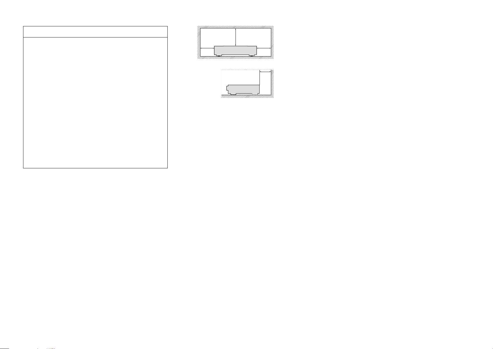
z z
z
Wall
z For proper heat dispersal, do not install this unit in a confined
space, such as a bookcase or similar enclosure.
•More than 12 in. (0.3 m) is recommended.
II
Getting started
Basic instructions
Advanced instructions
Information
DVD
Thank you for purchasing this Marantz product. To ensure proper operation, please read this owner’s manual carefully before using the product.
After reading this manual, be sure to keep it for future reference.
Contents
Getting started ·············································································· 1
Accessories ··················································································2
Features ························································································ 2
Cautions on handling ····································································3
Basic instructions ··································································4
Connections ··················································································· 5
Important information ··································································· 5
Connecting HDMI devices ···························································· 7
Connecting other devices ··························································· 12
Connecting to a home network (LAN) ········································ 20
Connecting the power cord ························································ 21
Setup ···························································································· 22
Set up speakers (Audyssey® Setup)············································22
Making the network settings (Network) ····································· 28
Playback (Basic operation) ························································· 29
Important information ································································· 29
Playing a Blu-ray Disc player/DVD player ···································· 30
Playing a CD player ····································································· 30
Playing an iPod············································································31
Playing a USB memory device ····················································34
Listening to FM/AM broadcasts ·················································37
Network content ········································································· 46
Listening to Internet Radio ·························································46
Playing back files stored on a PC and NAS ································· 49
Using online services ·································································· 53
Convenient functions ·································································· 64
AirPlay function ··········································································· 70
Selecting a listening mode (Sound Mode) ·······························72
Selecting a listening mode··························································72
Advanced instructions ······················································78
Installation/connection/setup of speakers (Advanced) ··········79
Speaker installation ····································································· 79
Speaker connection ···································································· 81
Set up speakers ·········································································· 91
Connections (Advanced connection)·········································93
Connecting the REMOTE CONTROL connectors ·······················93
Connecting an external control device ········································94
Playback (Advanced operation) ················································· 95
HDMI control function ································································ 95
Sleep timer function ···································································96
Web control function ·································································· 97
Dual backup memory function ···················································· 99
Panel lock function······································································99
Remote lock function································································100
Various memory functions ························································ 100
Playback in ZONE2 (Separate room) ······································· 101
Audio output ············································································· 101
Playback ···················································································· 101
Sleep timer function ·································································102
How to make detailed settings ················································ 103
Menu map ················································································103
Examples of menu screen displays ·········································· 105
Examples of menu and front display ········································106
Inputting characters ·································································· 107
Audio·························································································108
Video ························································································· 114
Inputs ························································································ 119
Speakers ··················································································· 123
Network ···················································································· 127
General ·····················································································131
Information ···········································································137
Part names and functions·························································138
Front panel ················································································ 138
Display ······················································································ 139
Rear panel ················································································· 140
Remote control unit ·································································· 141
Other information ·····································································143
Trademark information ······························································143
Surround ··················································································· 144
Relationship between video signals and monitor output ·········· 148
Explanation of terms ································································· 150
Troubleshooting ········································································ 153
Resetting the microprocessor ··················································157
Specifications ············································································158
1
Accessories
Basic instructions
Advanced instructions
Information
v See overleaf
DVD
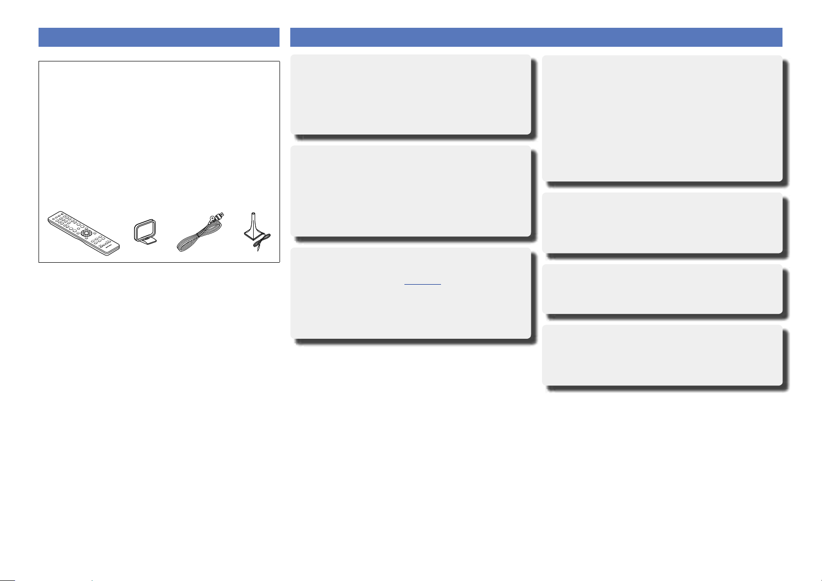
Check that the following parts are supplied with the product.
q Getting Started ........................................................................ 1
w CD-ROM (Owner’s Manual) .................................................... 1
e Safety Instructions .................................................................. 1
r Warranty card (for USA) .......................................................... 1
t Warranty card (for CANADA) ................................................... 1
y Power cord .............................................................................. 1
u Remote control unit (RC021SR) .............................................. 1
i R03/AAA batteries ................................................................... 2
o AM loop antenna ..................................................................... 1
Q0 FM indoor antenna .................................................................. 1
Q1 Setup and measurement microphone ..................................... 1
(ACM1HB)
Q2 Cable label ............................................................................... 1
u Q1o Q0
Features
Digital video processor upscales analog video
signals (SD resolution) to HD (720p/1080p) and 4K
This unit features a sophisticated video processor that can upscale
standard definition (SD) analog video content from legacy sources
such as a VCR to HD and is able to output at 4K resolution (3840
x 2160 pixels) for compatibility with newly available resolution 4K
TVs.
With discrete circuit technology, the power
amplifier provides identical quality for all 7
channels (50 Watts x 7 channels)
For optimum realism and stunning dynamic range, the power
amplifier section features discrete power devices (not integrated
circuitry).
By using high current, high power discrete power devices, the
amplifier is able to easily drive high quality speakers.
Supports Internet Radio, music, and photograph
streaming
Supports AirPlay® (vpage70)
You can enjoy a wide variety of content, including listening to
Internet Radio, playing audio files stored on your PC, and displaying
photographs stored on your PC on our television.
This unit also supports Apple AirPlay which lets you stream your
music library from an iPhone®, iPad®, iPod touch® or iTunes®.
Compatible with “Marantz Remote App” for
performing basic operations of the unit with an
iPad, iPhonez or Android smartphone
“Marantz Remote App” is application software that allows you to
perform basic operations with an iPad, iPhone, Android smartphone
or Android tablet such as turning the unit ON/OFF, controlling the
volume, and switching the source.
z Download the appropriate “Marantz Remote App” for iOS
and Android devices. This unit needs to be connected to your
LAN and the iPhone/iPod touch or other device needs to be
connected to the same network by Wi-Fi (wireless LAN).
“Setup Assistant” provides easy-to-follow setup
instructions
First select the language when prompted. Then simply follow the
instructions displayed on the TV screen to set up the speakers,
network, etc.
Easy to use Graphical User Interface
This unit is equipped with an easy to see Graphical User Interface
that uses menu displays and features colorful icons and easy to
understand controls for maximum ease of use.
HDMI connections enable quick connection to
various digital AV devices (7 inputs, 1 output)
The unit is equipped with 7 HDMI input connectors for connecting
devices with HDMI connectors, such as a Blu-ray Disc player,
game console, HD digital camcorder, HDTVs, etc.
2

Features
Basic instructions
Advanced instructions
Information
DVD
Supports HDMI (3D, ARC, Deep Color, “x.v.Color”,
Auto Lip Sync, 4K) and HDMI control function
(vpage7)
Advanced HDMI features are supported, including 3D passthrough,
Audio Return Channel, Auto Lip Sync, Deep Color and “x.v.Color”,
and HDMI CEC control functions. If a 4K digital video signal is input,
it is passed through the unit unchanged, and the GUI overlay will
adjust the resolution accordingly.
Direct play for iPod and iPhone via USB
(vpage16)
Music data from an iPod or iPhone can be played back if you
connect the USB cable supplied with the iPod via the USB port of
this unit, and also an iPod can be controlled with the remote control
that comes with this unit.
Multi-Room audio
Enjoy audio playback in your home theater and another room at
the same time.
M-XPort (Marantz-eXtension Port) (vpage19)
This unit is equipped with the M-XPort, a Marantz original innovation
that provides outstanding expandability. You can connect the
Wireless Receiver RX101 (sold separately) to this port.
Cautions on handling
•Before turning the power on
Check once again that all connections are correct and that there are
no problems with the connection cables.
•Power is supplied to some of the circuitry even when the unit is
set to the standby mode. When going on vacation or leaving home
for long periods of time, be sure to unplug the power cord from the
power outlet.
•About condensation
If there is a major dierence in temperature between the inside of
the unit and the surroundings, condensation (dew) may form on
the operating parts inside the unit, causing the unit not to operate
properly.
If this happens, let the unit sit for an hour or two with the power
turned o and wait until there is little dierence in temperature
before using the unit.
•Cautions on using mobile phones
Using a mobile phone near this unit may result in noise. If that
occurs, move the mobile phone away from this unit when it is in use.
•Moving the unit
Turn o the power and unplug the power cord from the power
outlet. Next, disconnect the connection cables to other system units
before moving the unit.
•About care
•Wipe the cabinet and control panel clean with a soft cloth.
•Follow the instructions when using a chemical cleaner.
•Benzene, paint thinner or other organic solvents as well as
insecticide may cause material changes and discoloration if brought
into contact with the unit, and should therefore not be used.
3

Basic instructions
Basic instructions
Advanced instructions
Information
Basic instructions
DVD
Basic instructions
Here we explain the connections and basic operation methods for this unit.
F Connections vpage5
F Setup vpage22
F Playback (Basic operation) vpage29
F Network content vpage46
F Selecting a listening mode (Sound Mode) vpage72
For speaker connections, see page81.
4
Connections
Basic instructions
Advanced instructions
Information
Basic instructions
DVD
Important information
Make connections before using this unit.
To create a home theater that can play back higher quality video and audio by fully utilizing the
capabilities of this unit and your video devices, connect this unit to each of your video devices with
HDMI cables.
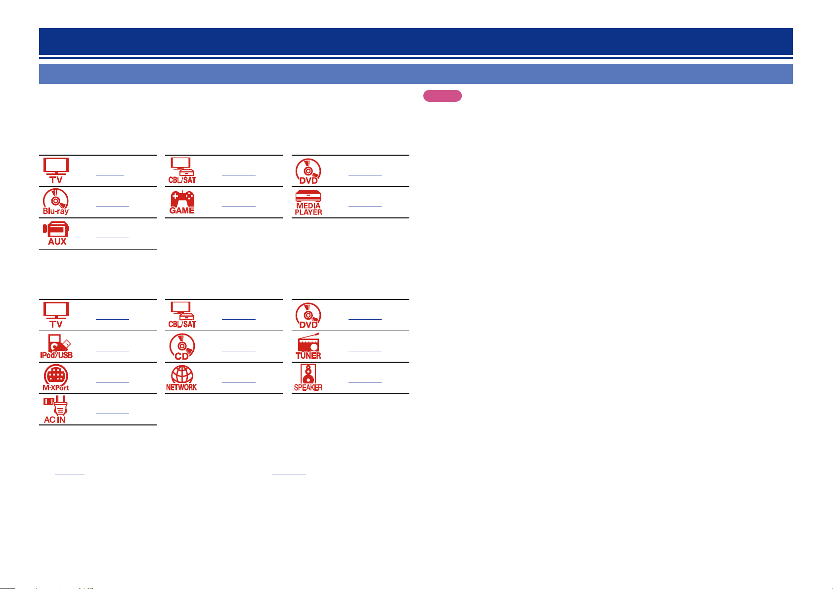
n HDMI devices
vpage9 vpage10 vpage10
vpage10 vpage10 vpage10
vpage10
If your video device does not support HDMI connections, use the following connection.
n Other devices
vpage13 vpage14 vpage15
NOTE
•When video signals are being upscaled to 4K output resolution, the menu screen is only displayed
on a 4K display that is connected to this unit via HDMI.
•Do not plug in the power cord until all connections have been completed. However, when the
“Setup Assistant” is running, follow the instructions in the “Setup Assistant” (C page 7) screen
for making connections. (During “Setup Assistant” operation, the input/output connectors do not
conduct current.)
•When running the “Setup Assistant” (C page 7), turn o the power supply of connected devices.
•When making connections, also refer to the operating instructions of the other devices being connected.
•Be sure to connect the left and right channels properly (left with left, right with right).
•Do not bundle power cords together with connection cables. Doing so can result in noise.
vpage16 vpage17 vpage18
vpage19 vpage20 vpage81
vpage21
This unit can change the source that is assigned to the DIGITAL AUDIO IN, ANALOG AUDIO IN,
COMPONENT VIDEO IN and VIDEO IN connectors.
For details on assigning a source to connectors, see “Changing the source assigned to connectors”
(vpage12). For the setting method, see “Input Assign” (vpage120).
5
Important information
Basic instructions
Advanced instructions
Information
Basic instructions
DVD
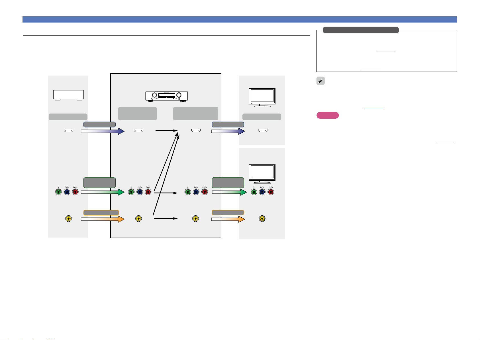
Converting input video signals for HD output (Video conversion function)
This unit is equipped with three types of video input connectors (HDMI, component video and composite video) and three types of video output
connectors (HDMI, component video and composite video).
This function automatically converts various formats of video signals input to this unit into the formats used to output the video signals from
this unit to a monitor.
GFlow of video signals for the MAIN ZONEH
Video device
Output
HDMI connector
This unit
Input
(IN)
HDMI signal HDMI signal
HDMI connector
Component video
signal
Output
(MONITOR OUT)
Component video
signal
HDMI-compatible TV
Input
HDMI connectorHDMI connector
HDMI-incompatible
TV
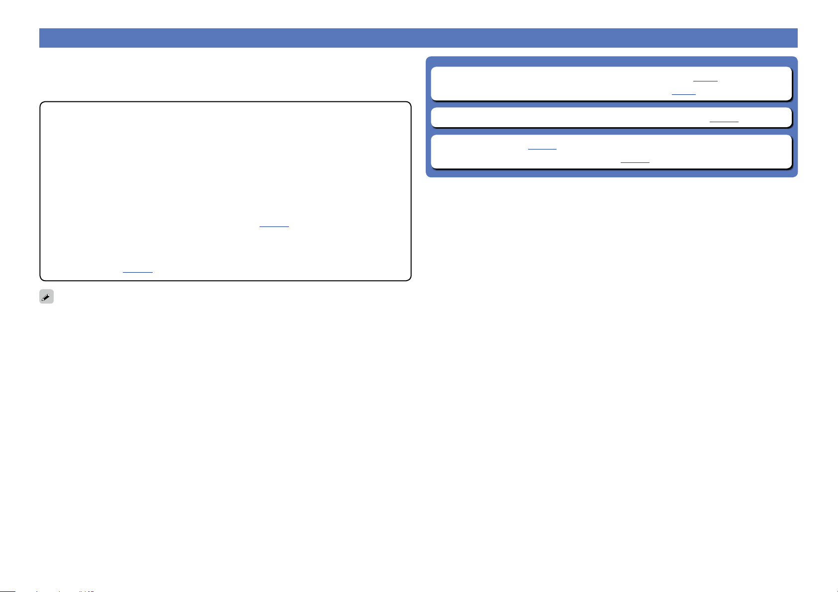
Make Settings as Necessary
•If you do not want this unit to convert video signals automatically,
use the following setting item to disable this function.
“Video Conversion” (vpage116)
•If you want to change the resolution of video signals output to
the TV, use the following setting item to do so.
“Resolution” (vpage117)
•The video conversion function supports the NTSC, PAL, SECAM,
NTSC 4.43, PAL-N, PAL-M and PAL-60 formats.
•Resolutions of HDMI-compatible TVs can be checked at “Video” –
“HDMI Monitor” (vpage134).
NOTE
•When a non-standard video signal from a game console or some
other source is input, the video conversion function might not
operate.
•HDMI signals cannot be converted into analog signals (vpage148).
For maximum flexibility with dierent video signal types and resolutions, this unit provides two important video processing functions. First,
it can convert standard definition composite video to digital HDMI. It also provides video upscaling from standard definition to high definition
resolutions, supporting 720p and 1080p HD outputs via HDMI, including 4K. If you have older legacy video sources such as a VCR and/or an
analog video camcorder, connect via the composite video connectors (yellow jacks). If you have an older DVD or HD player that is not equipped
with HDMI output but is equipped with component output, connect the player to the unit’s component video input. Pay attention to the
component video connection (it’s a three wire connection) so as to ensure that the jacks on the player match the component video input jacks
on this unit, otherwise you may not see a picture, or the picture will have distorted colors.
Component video
connectors
Video connector
Video signal
Component video
connectors
Video connector Video connector
Component video
connectors
Component video
connectors
Video signal
Video connector
6
Connecting HDMI devices
Basic instructions
Advanced instructions
Information
Basic instructions
DVD
You can connect up to eight HDMI-compatible devices (7-inputs/1-output) to the unit.
If the device connected to this unit is equipped with an HDMI connector, it is recommended to use HDMI
connections. Connections with an HDMI cable oer the following benefits that can not be achieved with
other connection methods.
n Before connecting this unit to TV via HDMI connections (vpage8)
n Connecting this unit to a TV via HDMI connections (vpage9)
•High quality playback by transmitting audio and video via digital signals
HDMI connections can transmit high definition video and high quality audio formats adopted by Bluray disc players (Dolby Digital Plus, Dolby TrueHD, dts-HD, dts-HD Master Audio).
HDMI connections also convey information required for playback between devices. The information
is used for copyright protection and TV resolution recognition, the ARC function, the HDMI control
function, etc.
•Transmission of audio and video signals with a single HDMI cable
Previous connections required multiple audio and video cables, but HDMI connections require only a
single HDMI cable to transmit audio and video signals. This allows wires in a home theater system,
which tend to be complicated, to be more easily organized.
•Mutual control through the HDMI control function (vpage95)
This unit and the HDMI device connected via HDMI can be linked to perform operations such as
power control, volume control, and input source switching.
•Other video and audio functions, such as 3D video playback, Content Type, the ARC function,
are supported (vpage11).
•There is more than one version of the HDMI standard. The supported functions and the performance
vary according to the version. This unit complies with the HDMI standard that supports the ARC and 3D
playback functions. To enjoy these functions, the HDMI device connected to this unit also needs to use
the same version of the standard. For the version of the HDMI standard on the device connected to this
unit, see the device’s manual.
•Some TVs do not support audio input via HDMI connections. For details, see your TV’s manual.
n Connecting this unit to video devices via HDMI connections (vpage10)
n HDMI function (vpage11)
n Settings related to HDMI connections (vpage11)
7
Connecting HDMI devices
Basic instructions
Advanced instructions
Information
Basic instructions
DVD
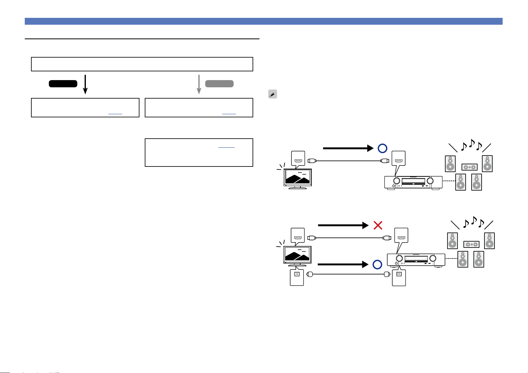
Before connecting this unit to TV via HDMI connections
There are 2 methods to connect an HDMI-compatible TV to this unit.
Use the connection method that suits your TV.
Does the TV to be connected to this unit support the ARC function?
Yes No
Connecting this unit to a TV via
HDMI connections (vpage9)
Connecting this unit to a TV via
HDMI connections (vpage9)
+
Connecting a TV (vpage13)
For audio connections, use a method other
than HDMI connections.
n About ARC (Audio Return Channel) function
This function plays TV audio on this unit by sending the TV audio signal to this unit via the HDMI cable.
If a TV without the ARC function is connected via HDMI connections, video signals of the playback
device connected to this unit are transmitted to the TV, but this unit can not play back the audio from
the TV. If you want to enjoy surround audio for TV program, a separate audio cable connection is
required.
In contrast, if a TV with the ARC function is connected via HDMI connections, no audio cable connection
is required. Audio signals from the TV can be input to this unit through the HDMI cable between this
unit and the TV. This function allows you to enjoy surround playback on this unit for the TV.
When the ARC function is used, connect a device with a “Standard HDMI cable with Ethernet” or “High
Speed HDMI cable with Ethernet” for HDMI.
Refer to the owner’s manual for your TV for details about TV connection and settings.
GConnection to a TV with the ARC functionH
Audio signals from the TV
IN OUT
HDMI cable
This unit SpeakersTV
GConnection to a TV without the ARC functionH
Audio signals from the TV
Audio from the TV
Audio from the TV
IN OUT
HDMI cable
Audio signals from the TV
Optical cable
This unit Speakers
INOUT
8
Connecting HDMI devices
Basic instructions
Advanced instructions
Information
Basic instructions
DVD
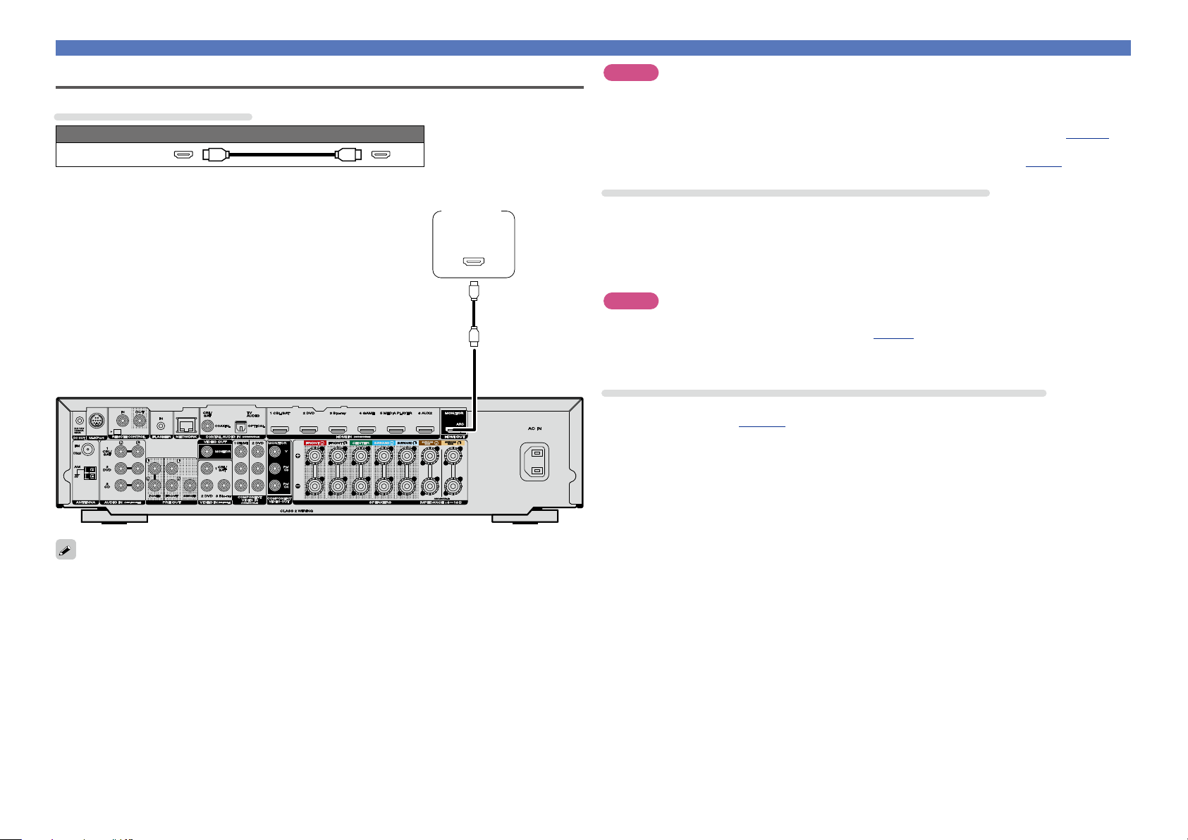
Connecting this unit to a TV via HDMI connections
Cables used for connections
Audio and video cable (sold separately)
HDMI cable
•This interface allows transfer of digital video signals and digital audio signals over a single HDMI cable.
TV
HDMI
IN
(ARC)
NOTE
•The audio signal from the HDMI output connector (sampling frequency, number of channels, etc.) may be
limited by the HDMI audio specifications of the connected device regarding permissible inputs.
•When connecting a TV that does not support the ARC function, an audio cable connection is
required in addition to the HDMI cable. In this case, refer to “Connecting a TV” (vpage13) for
the connection method.
For the ARC function, see “About ARC (Audio Return Channel) function” (vpage8).
Connecting to a device equipped with a DVI-D connector
The DVI-D (Digital Visual Interface) method is also used for video transmission via digital signals. This is
developed mainly for computers, and some displays such as projectors are equipped with this interface. To
output HDMI video signals to a DVI-D video input compatible device, use an HDMI/DVI conversion cable
or adapter.
The DVI-D connector can transmit high quality digital video signals, but copy guard and other issues may
hinder normal operations for some device combinations.
NOTE
•No sound is output when connected to a device equipped with a DVI-D connector. Make audio
connections as described in “Connecting a TV” (vpage13).
•Signals cannot be output to DVI-D devices that do not support HDCP.
•Depending on the combination of devices, the video signals may not be output.
Settings required when using a TV that supports the ARC function
When using a TV that supports the ARC function, make the following settings.
•Set “HDMI Control” (vpage116) to “On”.
•Video signals are not output if the input video signals do not match the display’s resolution. In this case,
switch the Blu-ray Disc/DVD player’s resolution to a resolution with which the display is compatible.
•When this unit and monitor are connected with an HDMI cable, if the display or monitor is not compatible
with HDMI audio signal playback, only the video signals are sent to the display or monitor.
9
Connecting this unit to video devices via HDMI connections
Basic instructions
Advanced instructions
Information
Basic instructions
DVD
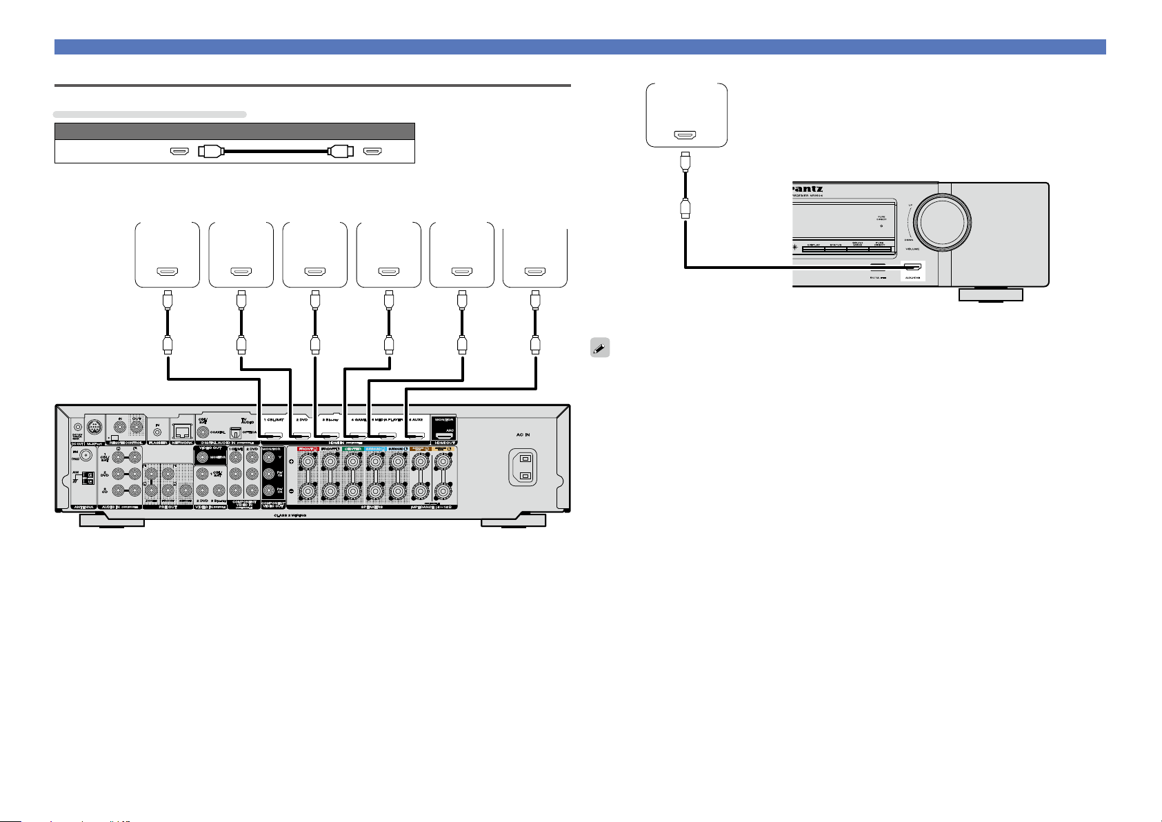
Cables used for connections
Audio and video cable (sold separately)
HDMI cable
Video
camcorder
(Primary)
HDMI
OUT
Connecting HDMI devices
Set-top
box
HDMI
OUT
DVD
player
HDMI
OUT
Blu-ray
Disc
player
HDMI
OUT
Game
console
HDMI
OUT
Media
player
HDMI
OUT
Video
camcorder
(Secondary)
HDMI
OUT
GRear panelH
GFront panelH
•When connecting a device that supports Deep Color or 4K, please use a “High Speed HDMI cable” or
“High Speed HDMI cable with Ethernet”.
•Video signals are not output if the input video signals do not match the display’s resolution. In this case,
switch the Blu-ray Disc/DVD player’s resolution to a resolution with which the display is compatible.
10

Connecting HDMI devices
Basic instructions
Advanced instructions
Information
Basic instructions
DVD
HDMI function
This unit supports the following HDMI functions:
n About 3D function
This unit supports input and output of 3D (3 dimensional) video signals of HDMI.
To play back 3D video, you need a TV and player that provide support for the HDMI 3D function and a
pair of 3D glasses.
NOTE
•When playing back 3D video, refer to the instructions provided in the manual of your playback device
together with this manual.
•When playing back 3D video content, the menu screen or status display screen can be superimposed
over the image. However, the menu screen or status display screen cannot be superimposed over
certain 3D video content.
•If 3D video with no 3D information is input, the menu screen and status display on this unit are displayed
over the playback video.
•If 2D video is converted to 3D video on the television, the menu screen and status display on this unit
are not displayed correctly. To view the menu screen and status display on this unit correctly, turn the
television setting that converts 2D video to 3D video o.
n About 4K function
This unit supports input and output of 4K (3840 x 2160 pixels) video signals over HDMI.
When a device supporting 4K is connected, use a cable compatible with “High Speed HDMI cable” or
“High Speed HDMI cable with Ethernet”.
n HDMI pass through function (vpage115)
Signals input to the HDMI input connector are output to the television or other device connected to the
HDMI output connector, even if the power of this unit is in standby.
n About Content Type
This function was added with the HDMI standard. It automatically makes settings suitable for the videooutput type (content information).
NOTE
To enable the Content Type, set “Video Mode” to “Auto” (vpage116).
n Deep Color (vpage150)
When a device supporting Deep Color is connected (such as an HD camcorder), use a cable compatible
with “High Speed HDMI cable” or “High Speed HDMI cable with Ethernet”.
n Auto Lip Sync (vpage115, 150)
n “x.v.Color”, sYCC601 color, Adobe RGB color, Adobe YCC601 color
(vpage150, 151, 152)
n High definition digital audio format
n ARC (Audio Return Channel) (vpage8)
Copyright protection system
In order to play back digital video and audio such as BD-Video or DVD-Video via HDMI connection, both
this unit and TV or the player need to support the copyright protection system known as HDCP (Highbandwidth Digital Content Protection System). HDCP is copyright protection technology comprised of
data encryption and authentication of the connected AV devices. This unit supports HDCP.
•If a device that does not support HDCP is connected, video and audio are not output correctly. Read
the owner’s manual of your television or player for more information.
Settings related to HDMI connections
Set as necessary. For details, see the respective reference pages.
n HDMI control function (vpage95)
This function allows you to operate external devices from the unit and operate the unit from external
devices.
NOTE
•The HDMI control function may not work depending on the device it is connected to and its settings.
•You cannot operate a TV or Blu-ray Disc player/DVD player that is not compatible with the HDMI control
function.
n HDMI Setup (vpage115)
Make settings for HDMI video/audio output.
•Auto Lip Sync •HDMI Pass Through •Pass Through Source
•HDMI Audio Out •HDMI Control •Power O Control
NOTE
To output audio signals that are input from the HDMI input connector to a TV connected via HDMI, set
“HDMI Audio Out” (vpage115) to “TV”.
Audio signals input via the Analog/Coaxial/Optical input connectors cannot be output from the HDMI
MONITOR output connector.
11

Connecting other devices
Basic instructions
Advanced instructions
Information
Basic instructions
DVD
For highest quality video and surround playback, it is recommended to
use an HDMI cable to connect this unit to TV and other video devices
(vpage7 “Connecting HDMI devices”).
This section describes alternate connection methods when your
device does not support HDMI connections.
Connection methods for various devices
Cables used for connections
Video cable (sold separately)
Component video
cable
Changing the source assigned to
connectors
This unit can change the source that is assigned to the HDMI IN,
DIGITAL AUDIO IN, COMPONENT VIDEO IN, VIDEO IN and AUDIO
IN connectors.
vpage13
vpage14
vpage15 vpage16
vpage17 vpage18
vpage19
vpage20
Video cable
Coaxial digital cable
Optical cable
Audio cable
LAN cable
Audio cable (sold separately)
L
R
Cable (sold separately)
L
R
Let us take a digital audio connection for Blu-ray Disc players for an
example. The rear panel digital audio input connectors do not have the
input connector indication for Blu-ray disc players (Blu-ray). However,
DIGITAL AUDIO IN connectors have the “ASSIGNABLE” indication,
which means that you can change the source assigned to these
connectors. You can assign Blu-ray disc players to these connectors
to use them for Blu-ray disc players. Select “Blu-ray” when switching
functions on this unit to play back the source connected to these
connectors.
n How to change the source assigned to
connectors (vpage120)
12
Connecting other devices
Basic instructions
Advanced instructions
Information
Basic instructions
DVD
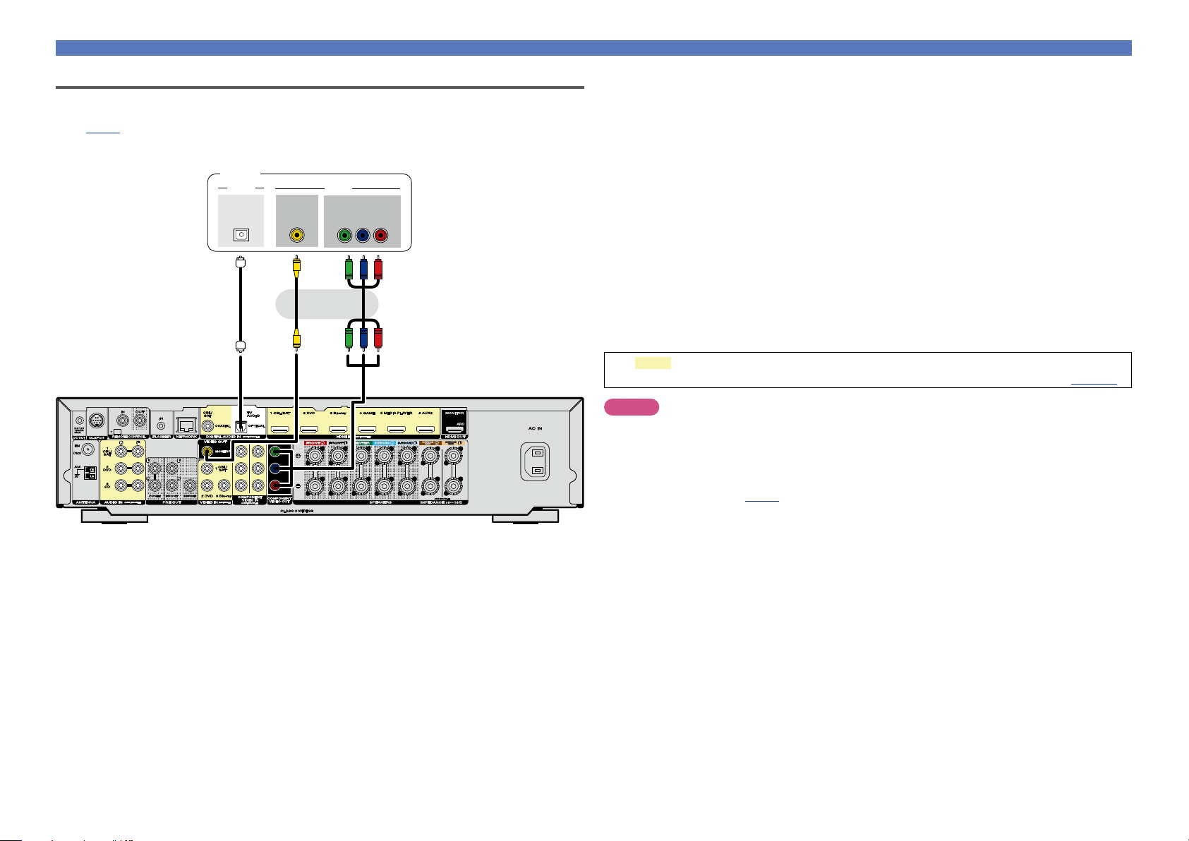
Connecting a TV
•This section describes how to connect when your TV does not support ARC (Audio Return Channel).
For instructions on HDMI connections, see “Connecting this unit to a TV via HDMI connections”
(vpage9).
•To listen to TV audio through this unit, use the optical digital connection.
TV
AUDIO
OPTICAL
OUT
a s a
VIDEO
IN
VIDEO
COMPONENT VIDEO
IN
B PR
Y P
or
n Audio connection
The following methods are available for connecting to this unit.
a DIGITAL AUDIO OPTICAL connector
When a multichannel audio (digital bit stream audio) is input, this unit decodes the audio to play
back surround sound.
n Video connection
The following methods are available for connecting to this unit. Use either of the methods to make
a connection.
The numbers prefixed with connectors indicate the recommendation order. The smaller the number is,
the higher playback quality is achieved.
a COMPONENT VIDEO OUT (MONITOR) connector
This makes an analog video connection. This connection method separates video signals into 3
signals for transmission based on color components, achieving the best quality video playback
among analog video connections, with less signal degradation.
s VIDEO OUT (MONITOR) connector
This makes an analog video connection.
The sections in the connection diagram are also available for connections. To connect devices
to these connectors, you must set up input connectors. For details, see “Input Assign” (vpage120).
NOTE
•The menu screen is only displayed on TV connected to this unit via HDMI. If your TV is connected
to this unit via other video output connectors, perform menu operations while seeing the display
on this unit.
•If you do not connect this unit to your TV via HDMI, do not make HDMI connections for video inputs
from other video devices, either. For details see “Converting input video signals for HD output (Video
conversion function)” (vpage6).
•When content on iPod, USB memory devices, or the network is being played back with your TV connected
to the COMPONENT VIDEO OUT or VIDEO OUT connector, screens output from this unit such as the
playback screen cannot be displayed.
13
Connecting other devices
Basic instructions
Advanced instructions
Information
Basic instructions
DVD
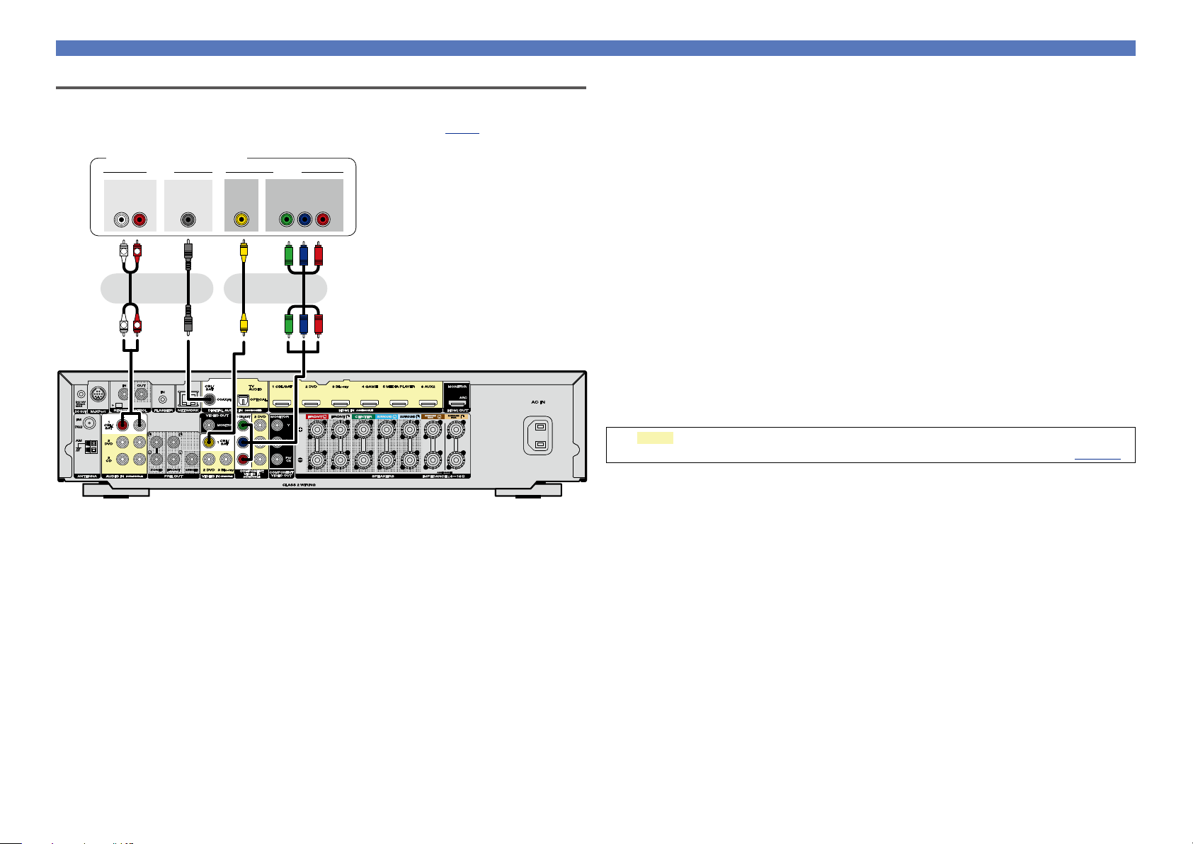
Connecting a set-top box (Satellite tuner/cable TV)
This section describes how to connect when your satellite tuner or cable TV does not support HDMI
connections.
For instructions on HDMI connections, see “Connecting HDMI devices” (vpage7).
Satellite tuner/Cable TV
AUDIO
AUDIO
OUT
L
RL
R
as as
COAXIAL
OUT
or or
R
L
VIDEO
OUT
VIDEO
COMPONENT VIDEO
OUT
B PR
Y P
n Audio connection
The following methods are available for connecting to this unit. Use either of the methods to make
a connection.
The numbers prefixed with connectors indicate the recommendation order. The smaller the number is,
the higher playback quality is achieved.
a DIGITAL AUDIO COAXIAL connector
When a multichannel audio (digital bit stream audio) is input, this unit decodes the audio to play
back surround sound.
s AUDIO IN (CBL/SAT) connector
This makes an analog audio connection.
n Video connection
The following methods are available for connecting to this unit. Use either of the methods to make
a connection.
The numbers prefixed with connectors indicate the recommendation order. The smaller the number is,
the higher playback quality is achieved.
a COMPONENT VIDEO IN (CBL/SAT) connector
This makes an analog video connection. This connection method separates video signals into 3
signals for transmission based on color components, achieving the best quality video playback
among analog video connections, with less signal degradation.
s VIDEO IN (CBL/SAT) connector
This makes an analog video connection.
The sections in the connection diagram are also available for connections. To connect devices
to these connectors, you must set up input connectors. For details, see “Input Assign” (vpage120).
14
Connecting other devices
Basic instructions
Advanced instructions
Information
Basic instructions
DVD
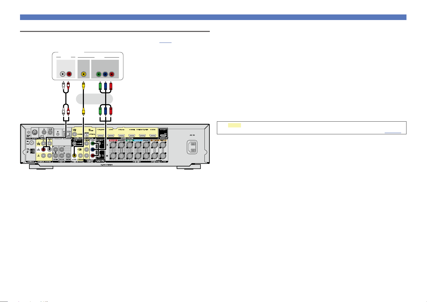
Connecting a DVD player
This section describes how to connect a DVD player that does not support HDMI connections.
For instructions on HDMI connections, see “Connecting HDMI devices” (vpage7).
DVD player
a
AUDIO
AUDIO
OUT
L
L
VIDEO
RL
R
R
OUT
VIDEO
COMPONENT VIDEO
OUT
B PR
Y P
as
or
n Audio connection
The following methods are available for connecting to this unit.
a AUDIO IN (DVD) connector
This makes an analog audio connection.
n Video connection
The following methods are available for connecting to this unit. Use either of the methods to make
a connection.
The numbers prefixed with connectors indicate the recommendation order. The smaller the number is,
the higher playback quality is achieved.
a COMPONENT VIDEO IN (DVD) connector
This makes an analog video connection. This connection method separates video signals into 3
signals for transmission based on color components, achieving the best quality video playback
among analog video connections, with less signal degradation.
s VIDEO IN (DVD) connector
This makes an analog video connection.
The sections in the connection diagram are also available for connections. To connect devices
to these connectors, you must set up input connectors. For details, see “Input Assign” (vpage120).
15
Connecting other devices
Basic instructions
Advanced instructions
Information
Basic instructions
DVD
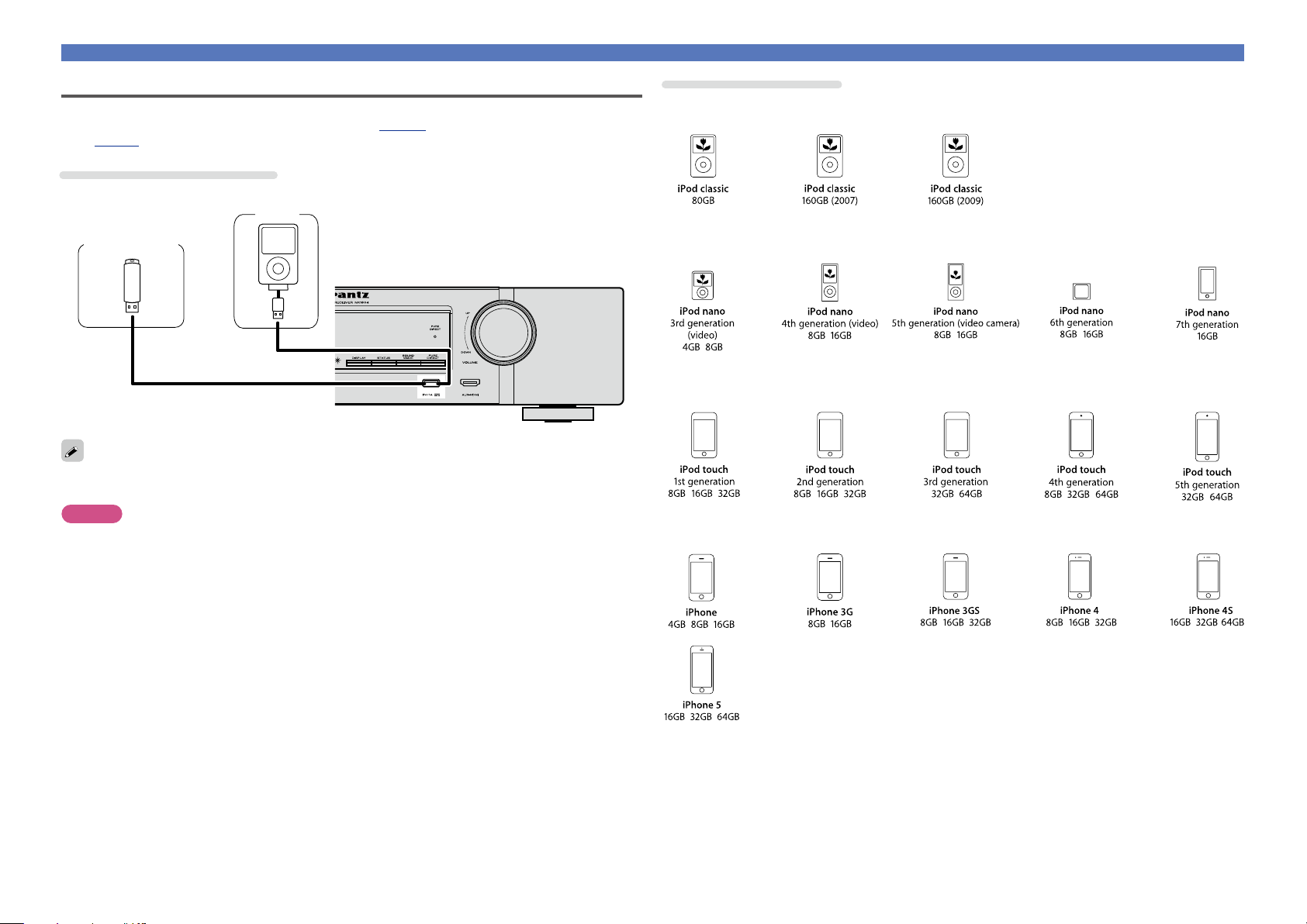
Connecting an iPod or USB memory device to the USB port
•You can enjoy music stored on an iPod or USB memory device.
•For operating instructions see “Playing an iPod” (vpage 31) or “Playing a USB memory device”
(vpage34).
Cables used for connections
To connect an iPod to this unit, use the USB adapter cable that was supplied with the iPod.
iPod
USB memory
device
or
Marantz does not guarantee that all USB memory devices will operate or receive power. When using a
portable USB hard disk drive (HDD) which came with an AC adapter, use that device’s supplied AC adapter.
NOTE
•USB memory devices will not work via a USB hub.
•It is not possible to use this unit by connecting the unit’s USB port to a PC via a USB cable.
•Do not use an extension cable when connecting a USB memory device. This may cause radio interference
with other devices.
•When connecting an iPhone to this unit, keep the iPhone at least 20 cm (8 inches) away from this unit.
If the iPhone is positioned close to this unit and a telephone call is received, noise may be output from
this unit.
•If the iPod is connected using an iPod cable (commercially available) that is longer than 2 meters (6 feet)
sound may not be played correctly. In this case, use a genuine iPod cable, or a cable that is shorter than
1 meter (3 feet).
Supported iPod models
•iPod classic
•iPod nano
•iPod touch
•iPhone
16
Connecting other devices
Basic instructions
Advanced instructions
Information
Basic instructions
DVD
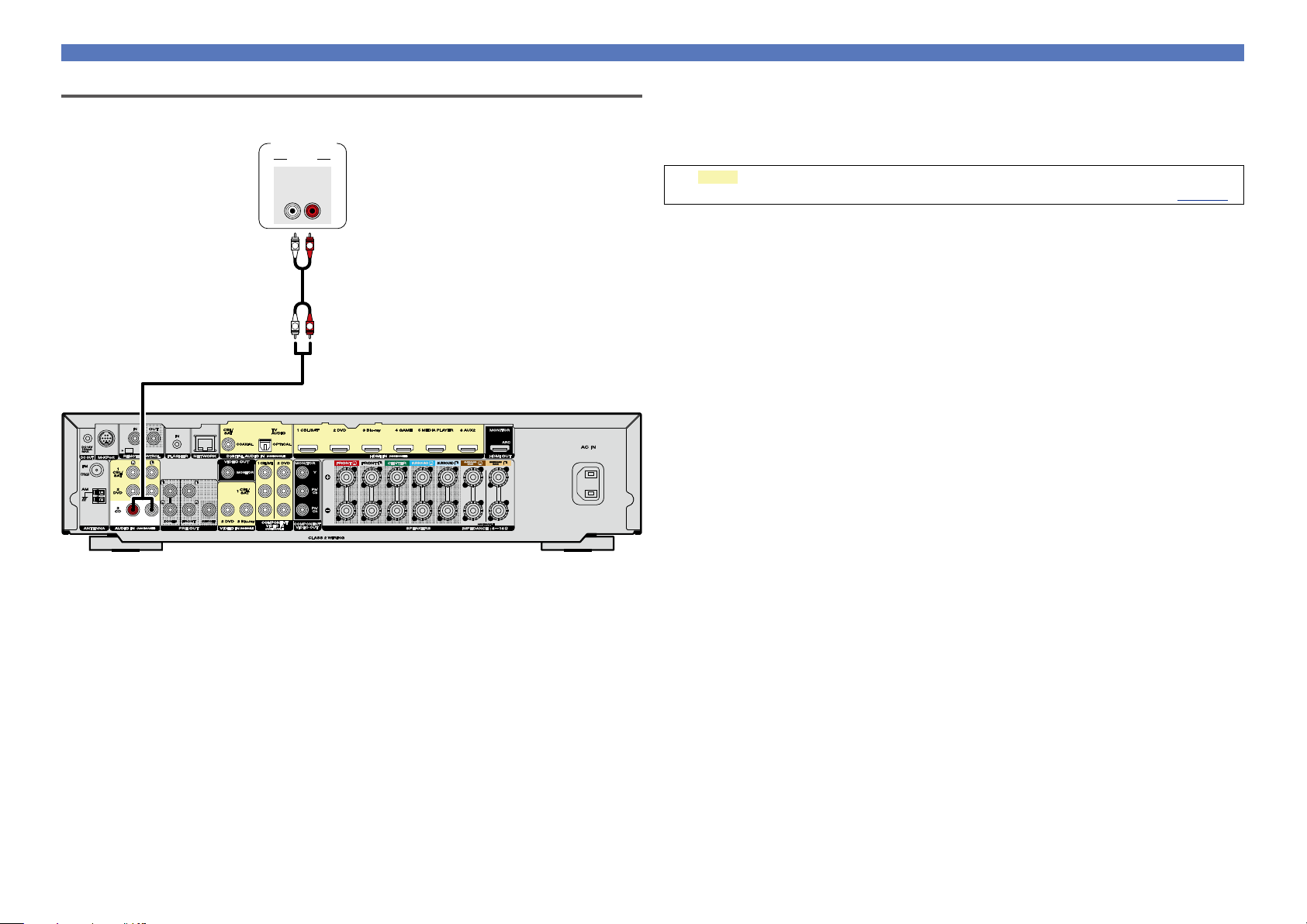
Connecting a CD player
You can enjoy CD sound with the player connected by digital or analog cables.
CD player
AUDIO
AUDIO
OUT
RL
R
L
a
R
L
n Audio connection
The following methods are available for connecting to this unit.
a AUDIO IN (CD) connector
This makes an analog audio connection.
The sections in the connection diagram are also available for connections. To connect devices
to these connectors, you must set up input connectors. For details, see “Input Assign” (vpage120).
17
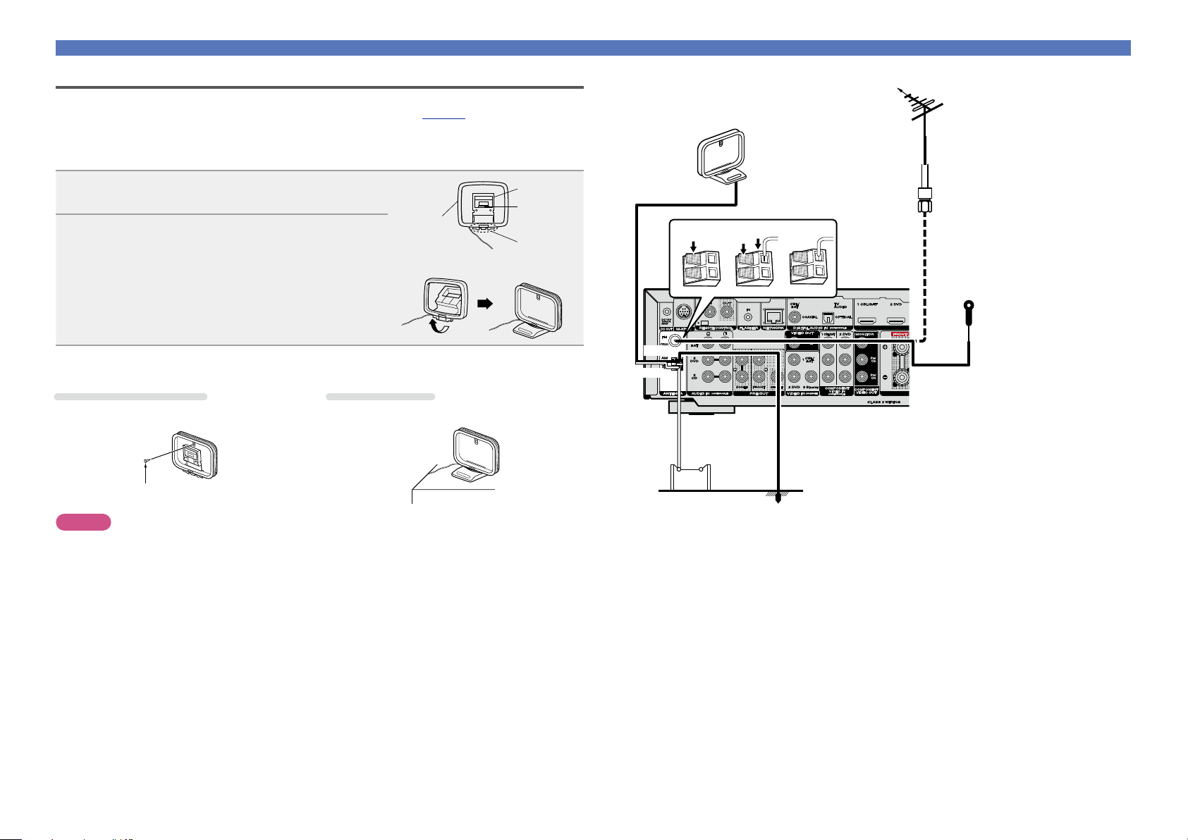
Connecting an FM/AM antenna
Basic instructions
Advanced instructions
Information
Basic instructions
DVD
Connecting other devices
Direction of broadcasting station
•Connect the FM antenna supplied with the unit to enjoy listening to radio broadcasts.
•After connecting the antenna and receiving a broadcast signal (vpage 37 “Listening to FM/AM
broadcasts”), fix the antenna with tape in a position where the noise level becomes minimal.
n AM loop antenna assembly
Put the stand section through the bottom of the
1
loop antenna from the rear and bend it forward.
Insert the projecting part into the square hole in
2
the stand.
Loop
antenna
Stand
Square
hole
Projecting
part
n Using the AM loop antenna
Suspending on a wall
Suspend directly on a wall without assembling.
Nail, tack, etc.
NOTE
•Do not connect two FM antennas simultaneously.
•Even if an external AM antenna is used, do not disconnect the AM loop antenna.
•Make sure the AM loop antenna lead terminals do not touch metal parts of the panel.
•If the signal has noise interference, connect the ground terminal (GND) to reduce noise.
•If you are unable to receive a good broadcast signal, we recommend installing an outdoor antenna. For
details, inquire at the retail store where you purchased the unit.
Standing alone
Use the procedure shown above to assemble.
AM loop antenna
Black
White
AM outdoor
antenna
(supplied)
w eq
FM outdoor
antenna
75 Ω/ohms
coaxial cable
FM indoor antenna
(supplied)
Ground
18
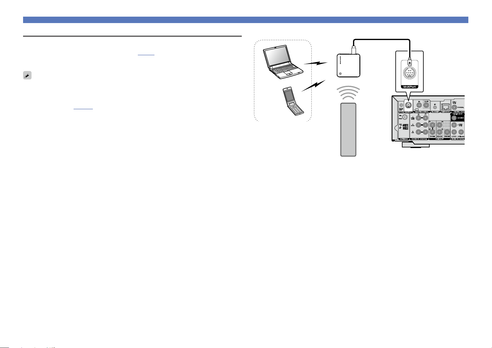
Connecting a wireless receiver (RX101)
Basic instructions
Advanced instructions
Information
Basic instructions
DVD
•You can connect a wireless receiver (RX101, sold separately) to play back music on your Bluetooth device
with this unit.
•To do this, switch the input source to “M-XPort” (vpage29 “Selecting the input source”).
•This unit supports the A2DP standard of the Bluetooth profile.
•See also the manuals for your wireless receiver and Bluetooth device.
•When connecting your Bluetooth device to the wireless receiver for the first time, paring is necessary.
Once paring is completed, the communication between your Bluetooth device and the wireless receiver
can be established just by connecting them. Paring is necessary for each Bluetooth device.
•You can also use the wireless receiver as an IR receiver. In this case, disable the remote control signal
receiving function (vpage100 “Remote lock function”).
Connecting other devices
Wireless receiver
(RX101)
Bluetooth device
(A2DP Compatibility)
Remote control unit
19
Connecting to a home network (LAN)
Basic instructions
Advanced instructions
Information
Basic instructions
DVD
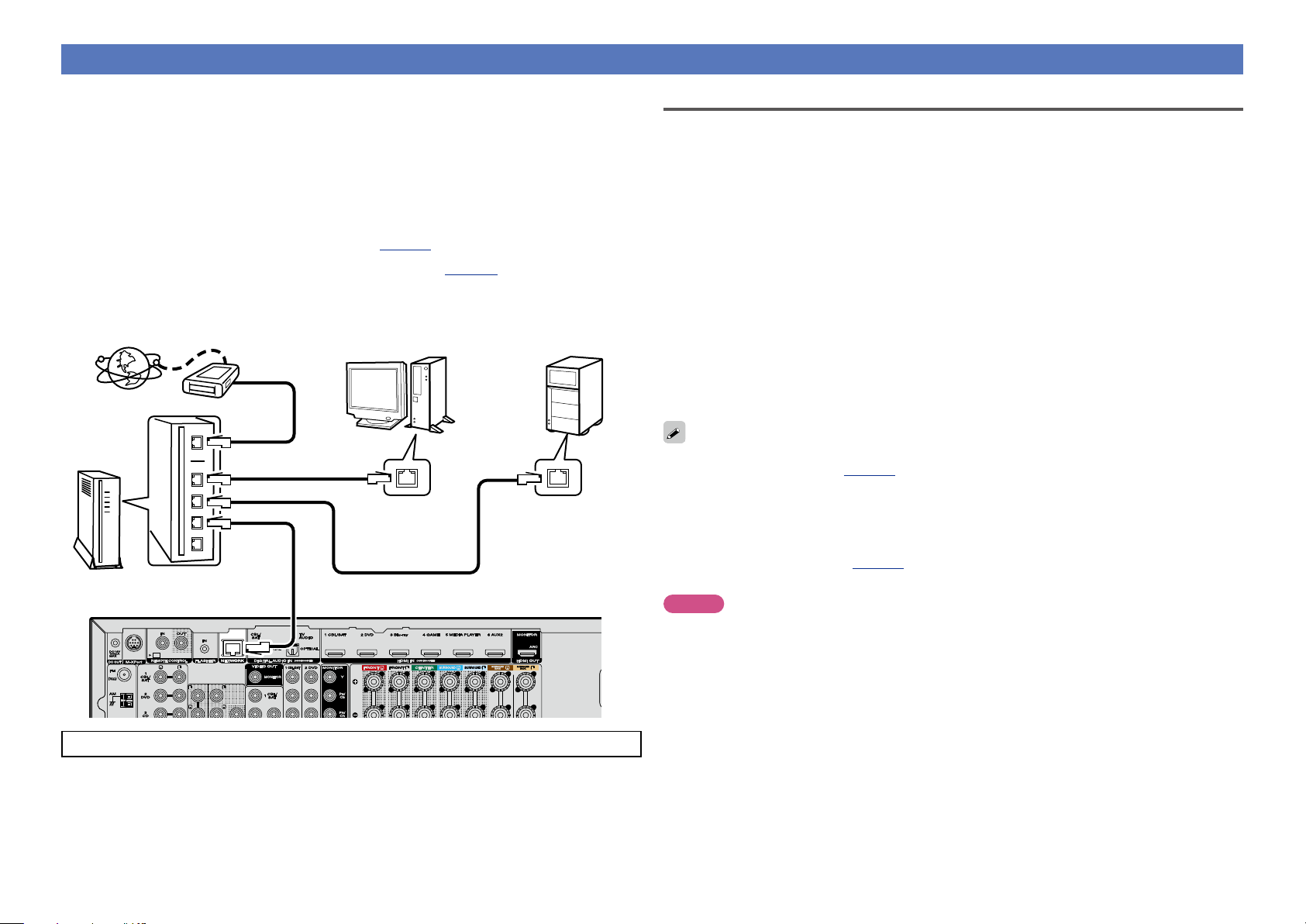
You can connect this unit to your home network (LAN) to perform various types of playbacks and operations
as follows. Make network connections for this unit by carefully reading information on this page.
•Playback of network audio such as Internet Radio and from your media server(s)
•Playback of music content from online streaming services
•Using the Apple AirPlay function
•Operation on this unit via the network
In addition, if updated firmware becomes available for this unit, the updated information is delivered from
us to this unit over the internet via your home network. You can then download and install the latest
firmware.
For more information, on the menu, select “Update” (vpage135).
Network settings are necessary. See “Network” on the menu (vpage 127) for more information on
network setting.
NAS
(Network Attached
PC
Modem
Internet
Storage)
Required system
n Broadband internet connection
n Modem
Device that connects to your broadband internet provider, and is very often supplied with the service .
A type that is integrated with a router is also often available.
n Router
When using this unit, we recommend you use a router equipped with the following functions:
•Built-in DHCP server
This function automatically assigns IP addresses on the LAN.
•Built-in 100BASE-TX switch
When connecting multiple devices, we recommend a switching hub with a speed of 100 Mbps or
greater.
n LAN cable
(CAT-5 or greater recommended)
•Use only a shielded STP or ScTP LAN cable which is easily available at electronics stores.
•The normal shielded-type LAN cable is recommended. If a flat-type cable or unshielded-type cable is
used, other devices could be aected by noise.
Router
For connections to the Internet, contact an ISP (Internet Service Provider) or a computer shop.
To WAN side
To LAN port
To LAN port
LAN port/
Ethernet
connector
LAN port/
Ethernet
connector
•If you have an Internet provider contract for a line on which network settings are made manually, make
the settings at “Network” (vpage127).
•With this unit, it is possible to use the DHCP and Auto IP functions to make the network settings
automatically.
•When using this unit with the broadband router’s DHCP function enabled, this unit automatically performs
the IP address setting and other settings.
When using this unit connected to a network with no DHCP function, make the settings for the IP
address, etc., at “Network” (vpage127).
•When setting manually, check the settings with the network administrator or internet service provider.
NOTE
•A contract with an internet service provider (ISP) is usually required to connect to the Internet.
No additional contract is needed if you already have a broadband connection to the Internet.
•The types of routers that can be used depend on the ISP. Contact your ISP or a computer shop for details.
•Marantz assumes no responsibility whatsoever for any communication errors or troubles resulting from
the customer’s network environment or connected devices.
•This unit is not compatible with PPPoE. A PPPoE-compatible router is required if you have a contract for
a type of line set by PPPoE.
•Do not connect an NETWORK connector directly to the LAN port/ Ethernet connector on your computer.
•To listen to audio streaming, use a router that supports audio streaming.
20
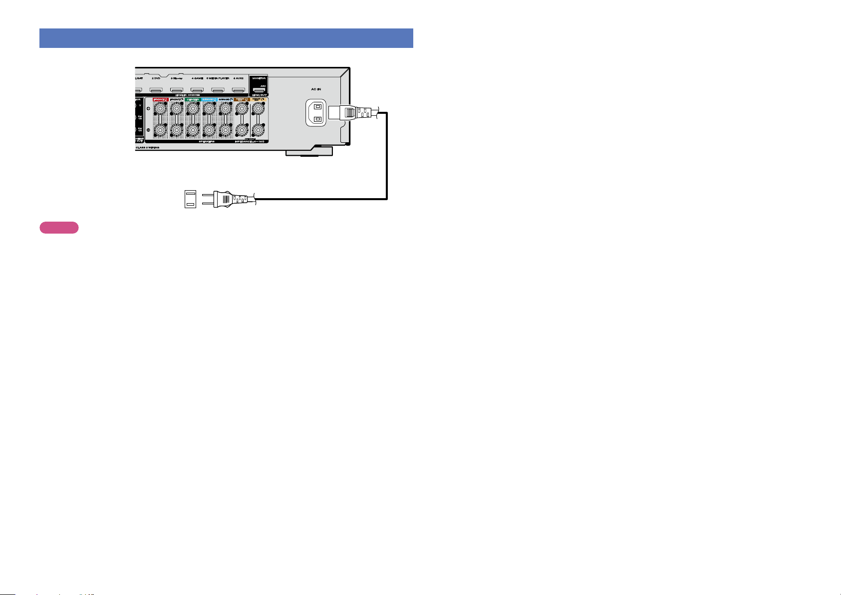
Connecting the power cord
Basic instructions
Advanced instructions
Information
Basic instructions
DVD
After completing all the connections, insert the power plug into the power outlet.
To household power outlet
(AC 120 V, 60 Hz)
NOTE
•Do not plug in the power cord until all connections have been completed. However, when the
“Setup Assistant” is running, follow the instructions in the “Setup Assistant” (C page 7) screen
for making connections. (During “Setup Assistant” operation, the input/output connectors do not
conduct current.)
•Do not bundle power cords together with connection cables. Doing so can result in humming or noise.
Power cord (supplied)
21
Setup
Basic instructions
Advanced instructions
Information
Basic instructions
v See overleaf
DVD
Here, we explain “Audyssey® Setup”, which allows you to automatically
make the optimal settings for your speakers, and “Network”, which
allows you to connect this unit to a home network (LAN).
This unit lets you play via your home network (LAN) music files stored
on a computer and music content such as that from Internet Radio.
n Speaker connection (vpage81)
n Set up speakers (Audyssey® Setup) (vpage22)
n Making the network settings (Network)
(vpage28)
Playback (Basic operation) (vpage29)
Selecting a listening mode (Sound Mode)
(vpage72)
Playback (Advanced operation) (vpage95)
Set up speakers (Audyssey® Setup)
The acoustic characteristics of the connected speakers and
listening room are measured and the optimum settings are made
automatically. This is called “Audyssey® Setup”.
To perform measurement, place the Setup and measurement
microphone in multiple locations all around the listening area.
For best results, we recommend you measure in six positions, as
shown in the illustration (up to six positions).
•When performing Audyssey® Setup, Audyssey MultEQ®/
Audyssey Dynamic EQ®/Audyssey Dynamic Volume® functions
become active (vpage112, 113).
•To set up the speakers manually, use “Speakers” (vpage123)
on the menu.
NOTE
•Make the room as quiet as possible. Background noise can disrupt
the room measurements. Close windows and turn o the power on
electronic devices (TVs, radios, air conditioners, fluorescent lights,
etc.). The measurements could be aected by the sounds emitted
by such devices.
•During the measurement process, place cell phones outside the
listening room. Cell phone signals could disrupt the measurements.
•Do not unplug the Setup and measurement microphone from the
main unit until Audyssey® Setup is completed.
•Do not stand between the speakers and Setup and measurement
microphone or allow obstacles in the path while the measurements
are being made. This will cause inaccurate readings.
•During the measurement process, audible test tones will come from
the speakers and subwoofer(s), but this is part of normal operation.
If there is background noise in the room, these test signals will
increase in volume.
•Operating
control unit or VOLUME on the main unit
during the measurements will cancel the
measurements.
•Measurement cannot be performed when
headphones are connected. Unplug the
headphones before performing Audyssey®
Setup.
VOLUME df on the remote
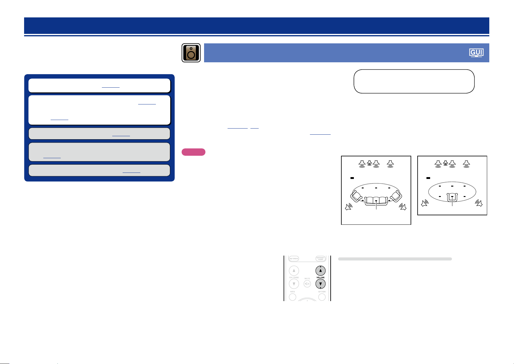
About Setup and measurement
microphone placement
•Measurements are performed by placing the Setup and measurement
microphone successively at multiple positions throughout the entire
listening area, as shown in GExample qH. For best results, we
recommend you measure in six positions, as shown in the illustration
(up to six positions).
•Even if the listening environment is small as shown in GExample wH,
measuring at multiple points throughout the listening environment
results in more eective correction.
GExample qH GExample wH
FL SW C FR
( : Measuring positions)
M
*
FL Front speaker (L) SW Subwoofer
FR Front speaker (R) SL Surround speaker (L)
C Center speaker SR Surround speaker (R)
SRSL
FL SW C FR
( : Measuring positions)
M
*
SRSL
About the main listening position (*M)
The main listening position is the position where listeners would
normally sit or where one would normally sit alone within the listening
environment. Before starting Audyssey® Setup, place the Setup and
measurement microphone in the main listening position. Audyssey
MultEQ® uses the measurements from this position to calculate
speaker distance, level, polarity, and the optimum crossover value for
the subwoofer.
22
Set up speakers (Audyssey® Setup)
Basic instructions
Advanced instructions
Information
Basic instructions
v See overleaf
DVD
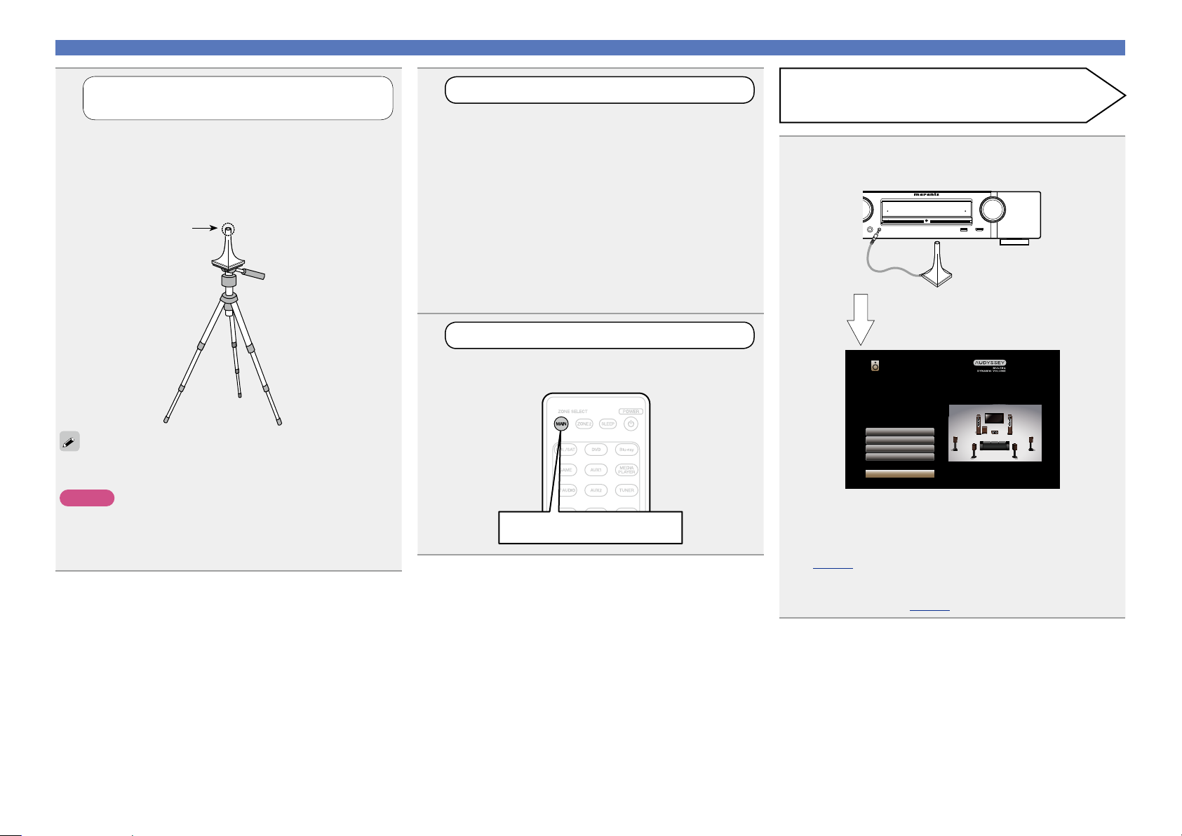
1
Prepare the included Setup and
measurement microphone
Mount the Setup and measurement microphone on
a tripod or stand and place it in the main listening
position.
When placing the Setup and measurement microphone, adjust
the height of the sound receptor to the level of the listener’s
ear.
Sound receptor
If you do not have a tripod or stand, set up the microphone on, for
example, a seat without a back.
NOTE
•Do not hold the Setup and measurement microphone in your hand
during measurements.
•Avoid placing the Setup and measurement microphone close to a
seat back or wall as sound reflections may give inaccurate results.
Setup and
measurement
microphone
2
Set up the subwoofer
If using a subwoofer capable of the following
adjustments, set up the subwoofer as shown below.
For details, see your subwoofer’s manual.
n When using a subwoofer with a direct mode
Set the direct mode to “On” and disable the volume adjustment
and crossover frequency setting.
n When using a subwoofer without a direct mode
Make the following settings:
•Volume : “12 o’clock position”
•Crossover frequency : “Maximum/Highest Frequency”
•Low pass filter : “O”
•Standby mode : “O”
3
Set up the zone mode
Press MAIN to switch the zone mode.
MAIN lights.
Press MAIN
Preparation
Connect the Setup and measurement microphone to
4
the SETUP MIC jack of this unit.
When the Setup and
measurement microphone is
connected, the following screen is
displayed.
Audyssey Setup
Your AV receiver can automatically measure the acoustics of
your room then optimize your speakers using the included
microphone.
Set the following items
if necessary.
Amp Assign
Channel Select
Check Results
Restore...
Start
•Here, we explain setup using the example of 7.1-channel speaker
playback.
For settings other than 7.1-channel speaker playback, select
“Amp Assign” and perform step 3 to 6 of “Set up “Amp Assign””
(vpage91).
If unused channels are set with “Channel Select”, measuring time
can be shortened. For setting, perform steps 7 to 12 of “Set up
“Channel Select”” (vpage92).
23
Set up speakers (Audyssey® Setup)
Basic instructions
Advanced instructions
Information
Basic instructions
v See overleaf
DVD
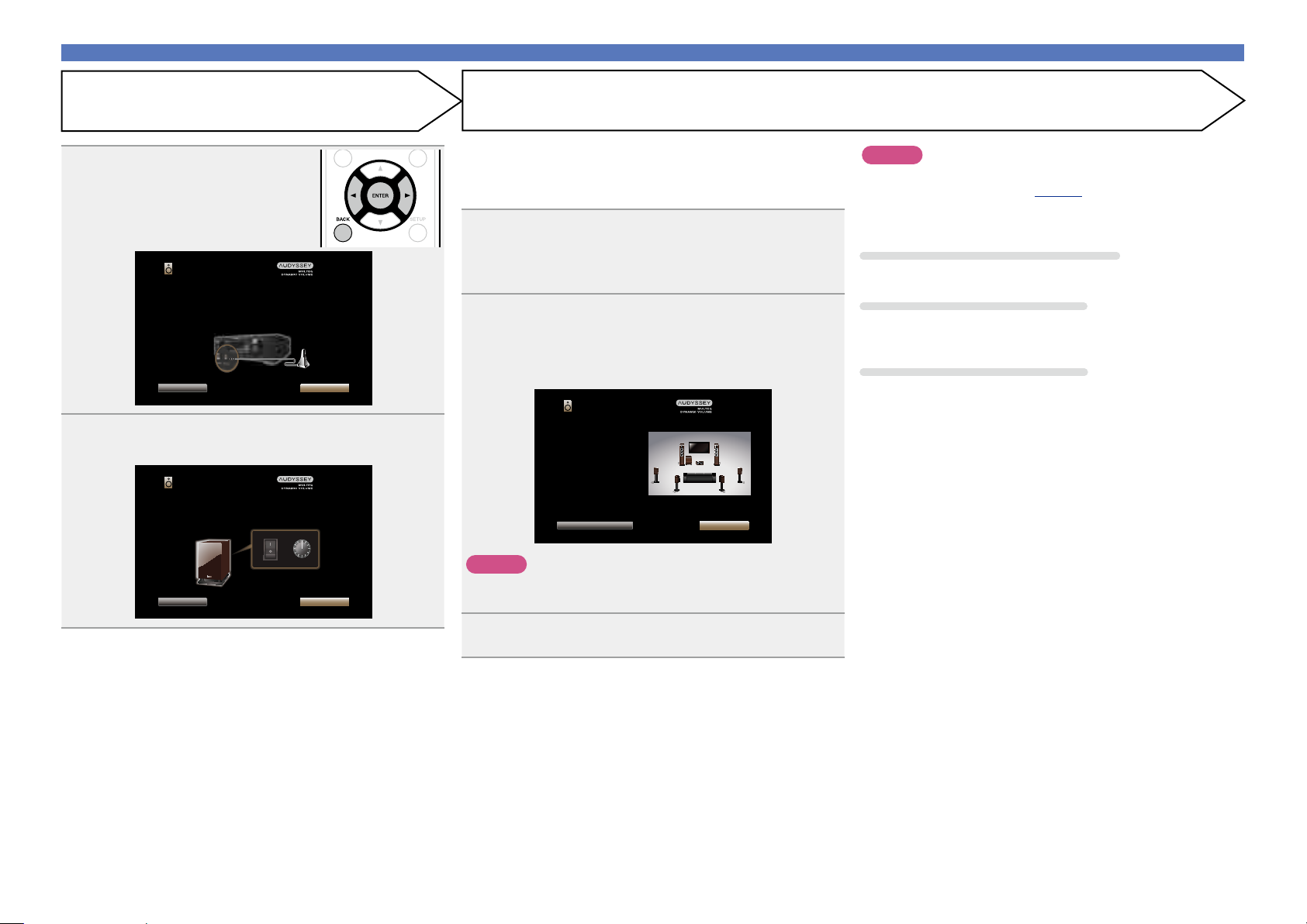
Preparation (Continued)
Select “Start” and then press
5
ENTER.
Audyssey Setup
Connect the calibration microphone to the SETUP MIC input
on the front the AV receiver.
Back Next
Select “Next” and then press ENTER.
6
The subwoofer volume setting screen is displayed.
Audyssey Setup
Make sure your subwoofer is plugged in and turned on. If your
subwoofer has a volume control on it, please set it at 50%...
VOLUMEPOWER
ON
MIN
OFF
Back Next
MAX
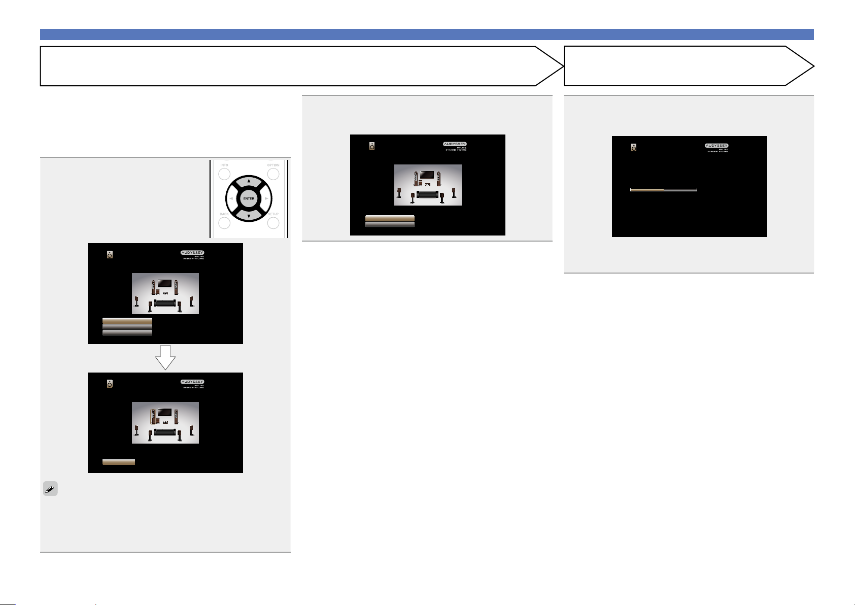
Detection & Measurement (Main)
This step automatically checks the speaker configuration and speaker
size, and calculates the channel level, distance, and crossover
frequency.
It also corrects distortion in the listening area.
Select “Begin Test” and then press ENTER.
7
When measuring begins, a test tone is output from each
speaker.
•Measurement requires several minutes.
The detected speakers are displayed.
8
•The illustration below shows an example of when the front
speakers, center speaker, subwoofer, surround and surround back
speakers have been detected.
Audyssey Setup
Speaker Detection
Front
Center
Subwoofer
Surround
Surr. Back
Repeat Last Test Next
NOTE
If a connected speaker is not displayed, the speaker may not be
connected correctly. Check the speaker connection.
:Yes
:Yes
:Yes
:Yes
:2spkrs
NOTE
If “Caution!” is displayed on TV screen:
Go to “Error messages” (vpage 27). Check any related items,
and perform the necessary procedures.
If the problem is resolved, return and restart “Audyssey® Setup”.
Going back to the previous screen
Select “Back” and then press ENTER.
When measuring has stopped
q Press BACK to display the popup screen.
w Press o to select “Yes”, and then press ENTER.
Setting up the speakers again
Repeat the operation from step 4.
Select “Next” and then press ENTER.
9
24
Set up speakers (Audyssey® Setup)
Basic instructions
Advanced instructions
Information
Basic instructions
v See overleaf
DVD
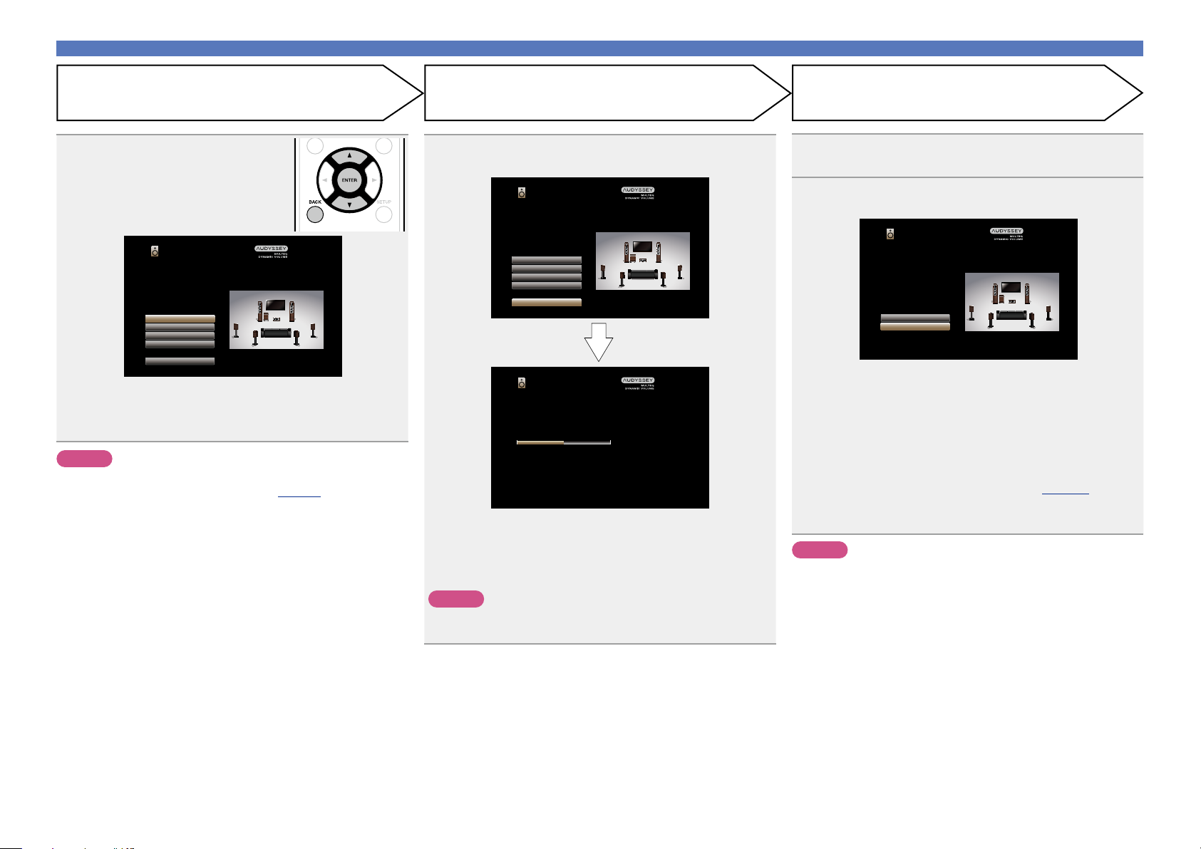
Measurement (2nd – 6th)
•In this step, you will perform measurements at multiple positions
(one to five additional positions) other than the main listening
position.
•Just one listening position can be measured if you so choose, but
measuring multiple positions increases the accuracy of the correction
of acoustic distortion within the listening area.
Move the Setup and
10
measurement microphone to
position 2, select “Continue”,
and then press ENTER.
The measurement of the second
position starts. Measurements can be
made in up to six positions.
Audyssey Setup
Place the microphone at ear level at the 2nd listening position,
then select “Continue”...
Continue
Calculation
Back
Repeat step 10, measuring positions 3 to 6.
11
When measurement of position 6 is completed, a
“Measurements finished.” message is displayed.
Audyssey Setup
Measurements finished.
Calculation
Repeat Last Test
Calculation
Select “Calculation” and then press ENTER.
12
Measuring results are analyzed, and the frequency response of
each speaker in the listening room is determined.
Audyssey Setup
Calibration completed! Now calculating...Please wait.
50%
•Analysis takes several minutes to complete. The more speakers
and measurement positions that there are, the more time it takes
to perform the analysis.
•To skip measuring the second and subsequent listening position,
use i to select “Calculation” and press ENTER to proceed to step
13.
•To measure the second position again, use i to select “Repeat
Last Test” and press ENTER.
Audyssey Setup
Measuring the LEFT FRONT SPEAKER...
Cancel
25
Set up speakers (Audyssey® Setup)
Basic instructions
Advanced instructions
Information
Basic instructions
DVD
Store FinishCheck
Use ui to select the item you
13
want to check, and then press
ENTER.
Audyssey Setup
Check processing results. To proceed, press “Store”.
Speaker Config.
Distances
Levels
Crossovers
Store
•Subwoofers may measure a greater reported distance than
the actual distance due to added electrical delay common in
subwoofers.
•If you want to check another item, press BACK.
NOTE
•If the result diers from the actual connection status, or if “Caution!”
is displayed, see “Error messages” (vpage 27). Then carry out
Audyssey® Setup again.
• If you change speaker positions or orientation, perform Audyssey®
Setup again to find the optimal equalizer settings.
Select “Store” and then press ENTER.
14
Save the measurement results.
Audyssey Setup
Check processing results. To proceed, press “Store”.
Speaker Config.
Distances
Levels
Crossovers
Store
Audyssey Setup
Now storing...Please wait.
50%
•Saving the results requires about 20 seconds.
•During saving of measurements results, “Now storing...Please
wait.” is displayed. When saving is completed, “Storing complete.
Audyssey® Setup is now finished. Please unplug microphone.” is
displayed.
NOTE
During saving of measurement results, be sure not to turn o the
power.
Unplug the Setup and measurement microphone
15
from the unit’s SETUP MIC jack.
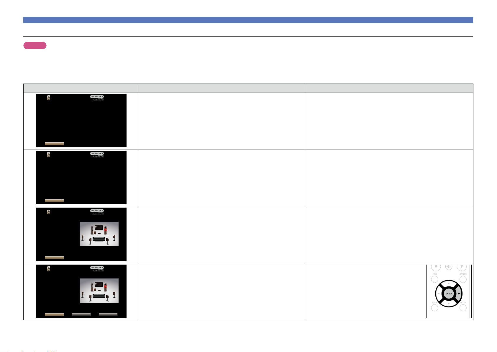
Set Audyssey Dynamic Volume®.
16
Audyssey Setup
You can set Dynamic Volume function, which automatically
adjust volume level for all content.
Do you want to enable?
Yes
No
•This feature adjusts the output volume to the optimal level while
constantly monitoring the level of the audio input to the unit.
Optimal volume control is performed automatically without any
loss in the dynamism and clarity of the sound when, for example,
the volume suddenly increases for commercials shown during
television programs.
n When turning Dynamic Volume on
•Press u to select “Yes”, and then press ENTER.
The unit automatically enters “Medium” (vpage113) mode.
n When turning Dynamic Volume o
•Press i to select “No”, and then press ENTER.
NOTE
After performing Audyssey® Setup, do not change the speaker
connections or subwoofer volume. In event of a change, perform
Audyssey® Setup again.
26
Set up speakers (Audyssey® Setup)
Basic instructions
Advanced instructions
Information
Basic instructions
DVD
Error messages
NOTE
•An error message is displayed if Audyssey® Setup could not be completed due to speaker placement, the measurement environment, etc. If an error message is displayed, check the relevant items and perform the
necessary measures. Then perform Audyssey® Setup again.
•If the result still diers from the actual connection status after re-measurement or the error message still appears, it is possible that the speakers are not connected properly. Turn this unit o, check the speaker
connections and repeat the measurement process from the beginning.
•Be sure to turn o the power before checking speaker connections.
Examples Error details Measures
Audyssey Setup
Caution! : Please check the cable connection and retry.
Microphone or Speaker is None
Retry
•The connected Setup and measurement microphone is broken, or a device
other than the supplied Setup and measurement microphone is connected.
•Not all speakers could be detected.
•Connect the included Setup and measurement microphone to the SETUP
MIC jack of this unit.
•Check the speaker connections.
Audyssey Setup
Caution!
Ambient noise is too high or level is too low
Retry
Audyssey Setup
Caution! : Please check the cable connection and retry.
Front R :None
Retry
Audyssey Setup
Caution! : Please check the cable connection and retry.
Front R :Phase
Retry Skip ErrorPhase Info.
•There is too much noise in the room for accurate measurements to be
made.
•Speaker or subwoofer sound is too low for accurate measurements to be
made.
•The displayed speaker could not be detected.
(The screen on the left indicates that the front right speaker cannot be
detected.)
•The displayed speaker is connected with the polarity reversed.
(The screen on the left indicates that the polarity phases of the front right
speakers are reversed.)
•Either turn o any device generating noise or move it away.
•Perform again when the surroundings are quieter.
•Check the speaker installation and the direction in which the speakers are
facing.
•Adjust the subwoofer’s volume.
•Check the connections of the displayed speaker.
•Check the polarity of the displayed speaker.
•For some speakers, this error message may be
displayed even if the speaker is properly connected.
If you are sure the connection is correct, use p to
select “Skip Error”, then press ENTER.
27
 Loading...