

Page 1
MZK58 User Guide
MZK58
Karaoke Digital Amplifier
卡拉 OK 数码放大器
使用说明书
Page 2
中文
感谢您惠购 MZK58卡拉OK数码放大器。
在使用卡拉OK数码放大器之前,请务必通读本使用手册,以利用好MZK58的所有功能。读完之
后,请将本手册和保修书妥善保管,以备将来查阅。
本手册对于理解卡拉OK数码放大器和解决使用中出现的问题很有帮助。
主要性能
输出功率 150W+150W(8 Ω 10%THD)
●
4 线输入:自动按序优先功能
●
内置高质量数字回音
●
可同时使用 5 支麦克风
●
内置主调遥控器:在 ±6 个方位上允许变换
●
±3 个音调(曲终时自动复原)
低音增强功能
●
无线遥控装置 (可调节音乐音量、麦克风音
●
量、主调控制器)
目录
警告 .......................................................................................................................................................................... 1
安全注意事项 ...................................................................................................................................................... 1
使用注意事项 ...................................................................................................................................................... 2
连接前的准备 ...................................................................................................................................................... 2
部件名称及其功能 ............................................................................................................................................ 3
系统的连接 ........................................................................................................................................................... 8
连接方法 ................................................................................................................................................................ 9
音像转换原理 ................................................................................................................................................... 11
自动音像选择 ................................................................................................................................................... 11
遥控功能 ............................................................................................................................................................. 12
一般操作 ............................................................................................................................................................. 13
要将音量旋钮停在所需位置 ..................................................................................................................... 14
保养注意事项 ................................................................................................................................................... 14
故障的排除 ........................................................................................................................................................ 15
售后服务 ............................................................................................................................................................. 15
使用礼仪 ............................................................................................................................................................. 15
版权 ....................................................................................................................................................................... 16
技术规格 ............................................................................................................................................................. 16
Page 3
警告
NO!
OFFON
OFFON
MUSIC VOLUME
BASS BOOST
DVD
OFFON
POWER
MIN MAX
MIC MASTER VOLUME
MIN MAX
ONOFF
F. B EQ
CD AUX BGM
1/A
DELAYREPEATTREBLEMIDBASSTREBLEMIDBASS
2/B 3 1 2
MIC INPUT3MIC VOLMIC 3 ECHO
ECHOMICMUSICBGM
BALANCE
RL
ECHO VOLUME
MAXMIN
KARAOKE DIGITAL AMPLIFIER
MZK58
♭6♭5♭4♭3♭2♭1♯1♯2♯3♯4♯5♯
6
KEY CONTROL
: :
@
.
rackMZK58
leg leg
- 不要让本器材曝露于雨水或湿气之中。
- 不要移除本器材的外盖。
- 不要从通风孔将任何物品推入本器材内。
- 不要用潮湿的手处理主电源电线。
- 不要使诸如桌布,报纸,窗帘等任何物品遮盖住通风口。
- 不要将诸如点燃的蜡烛等明火火源置于本器材上。
- 当丢弃废旧的电池之前,请遵守当地的政府法规及环
境保护规则。
安全注意事项
万一发现异常
在使用时万一发现有异常的噪音或气味产生,请立即关闭电
源,从插座上拔下电源线,并向经销商或维修中心咨询,要
求做一次检查。
勿擅自打开本体
- 在功放机的各侧保留 0.1 米的空间。
- 切勿将盛有液体的物品,如花瓶,置于本机上。
- 当开关位于 OFF 处时,本设备并未完全与 MAINS 切断 。
- 为使
本产品与主电源完全分离,要求使用时能从电源
插座上拔下插头。
- 使用时,为了完全切断主电源与本产品的连接,请将
本产品的插头放在近旁,使其能够立刻从电源插座上
拔下插头。
严禁水滴和异物
切勿从本体的通气孔或其他开口处插入或掉入象发夹、铁钉
和硬币之类的金属物以及诸如纸张、火柴之类的易燃物,因
为这会引起勿操作或是火灾和电击。万一水滴或异物进入了
本体,请让维修中心或经销商做一次检查。
中文
本体中使用了高压元件。请勿打开外壳,试图检查或改装本
体,以免遭受电击的危险。由于用户的改装而引起机器功能
下降或是误操作,将不属产品质量保证范围之内。
请勿超过最大功率容量
后面板 AC OU TLETS 端的部件与其他立体声系统的部件连
接。但是,请勿连接总功耗超过后面板标出的功率容量的部
件。否则会引起故障或火灾。同时也请注意:电源打开时,
不能将有大电流流过的部件(例如电视机)连接到 AC 输出口,
除非它已经设计成能与这类设备连接。
不要损坏电源线
在插上或是拔下电源线时请握住电源线的插头部分。不要用
湿的手去拔取或触摸电源线,这会导致短路或是触电事故。
不要将电源线铺设在本体和家具之下,物体之间。也不要将
电源线和其他的电源线捆在一起,不要给电源线打结或是将
其放置在人经常走动的地方。
当长期不使用时
当您长时间不在家时,例如外出旅游等,请关掉电源并从电
源插座上拔下电源线。这将防止由于本体的意外情况而引起
的火灾。
使用时的通风
机架尺寸必须遵守下面的测量规定:
MZK58 的 R/L 侧和机架的 R/L 侧之间的距离应大于 5cm。
q
MZK58 上侧和机架之间的距离应大于 10cm。
w
机架后方必须敞开。※请勿拆除支架腿。
e
不能遮挡或遮盖本体的通风口。万一产生这种情形,本体内
部的温度将上升并引起火灾。在本体外壳的上下部都开设有
通风口以防止本体过热。
1
Page 4
2
中文
使用注意事项
勿将本体设置在下列场所:
●
遭受直射阳光或附近有诸如取暖器之类的散热源的
地方。
●
因通风差而不易散热的地方,或是非常潮湿、多尘
的场所。
●
多振动或有斜面的不安稳之处。
●
靠近窗边等有雨水的地方。
●
靠近厨房等散发煤烟、蒸汽或热量的地方。
连接前的准备
连接注意事项
●
在做任何连接之前,确认各有关的电器设备的电源
都处于关闭状态。
●
功放机上“白色”的输入/输出插孔是用来连接左
声道,而“红色”插孔是用来连接右声道的。确认左、
AC 电源输出口的功耗
●
注意,总功耗不能超过后面板标出的瓦数。除系统
部件外,请勿将其他设备连接到本机的电源输出口。
●
请勿将电视机连接至本机,即使电视机标出的功耗
值小于允许值,因为当电视机打开时,功耗会增大。
右声道,是否被正确地连接。
●
将所要连接的导线的插头完全地插入插孔。如果连
接不完全的话。可能不产生音响或是出现噪音。
●
当从电源插座上拔下电源线时,必须握住电源线插
头部分的塑造物拔取。
「根据电子信息产品污染控制管理办法的有毒・有害物质或元素的标识表」
有毒有害物质或元素
零部件名称 对象零部件
电路板组件,安装・插入
电路板
机壳
特定电子零部件
零部件,电路板(不包括
特定电子零部件)
顶盖,底盖,底壳,框架,
垫片,螺丝等(金属,塑
胶),(包含的接合材料)
变压器,插入物,电源插
座,电源用大型电解质电
容器等电子零部件,机内
连结线
铅
(Pb)
X ○ X ○ ○ ○
X ○ ○ ○ ○ ○
X ○ ○ ○ ○ ○
汞
(Hg)
镉
(Cd)
六价铬
(Cr6+)
多溴联苯
(PBB)
多溴二苯醚
(PBDE)
备注
遥控器 /AC 适配器、电源
附件
备注:
○ :在该零部件的所有均质材料中的有毒有害物质的含量不超过在 SJ / T11363 - 2006 标准规定的限量要求
X :在该零部件中至少一种均质材料中的有毒有害物质的含量超过在 SJ / T11363 - 2006 标准规定的限量要求
(× 判定:包括 EU RoHS 的豁免项目)
线、RCA 信号线等附件,
包装
X ○ ○ ○ ○ ○
此标志是根据 2006 / 2 / 28 颁布的「电子信息产品污染控制管理办法」,以及「电子信息产品污染
控制标识要求」,适用于在中国销售的电子信息产品的环保使用期限。只要遵守此产品相关的安全和使
用注意事项,在从生产日期起计算的此年限内,产品中的有害物质不会往外泄漏,或者引起突然变异
而给环境污染,人体或财产带来重大影响。另外,包装在一起的电池等消耗品的环保期限的技术寿命
为 5 年。产品使用终结需废弃时,请遵守当地的电子信息产品回收・再利用相关的法律・规定。
Page 5
3
中文
部件名称及其功能
OFFON
OFFON
MUSIC VOLUME
BASS BOOST
DVD
OFFON
POWER
MIN MAX
MIC MASTER VOLUME
MIN MAX
ONOFF
F. B EQ
CD AUX BGM
1/A
DELAYREPEATTREBLEMIDBASSTREBLEMIDBASS
2/B 3 1 2
MIC INPUT
3
MIC VOLMIC 3 ECHO
ECHOMICMUSICBGM
BALANCE
RL
ECHO VOLUME
MAXMIN
KARAOKE DIGITAL AMPLIFIER MZK58
♭6♭5♭4♭3♭2♭
1
♯1♯2♯3♯4♯5♯
6
KEY CONTROL
1 2 3 4 5 6 7 8 9 10
18 17 16 15 14 13 12 11
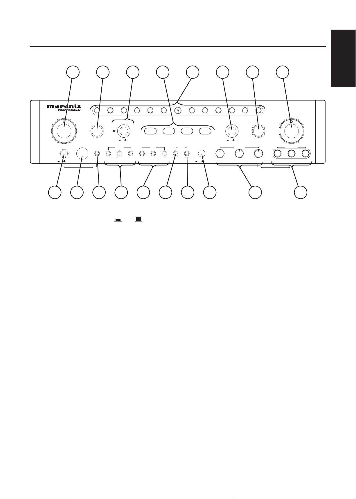
前面板
POWERSwitch电源开关(ON /OFF )
q
按下开关接通电源,再一次按下开关时将切断电
ECHODELAY 回音延迟
u
本控制装置用于调节延迟时间。
源。
MIC 3 ECHO ON/OFF SWITCH 麦克风 3 回音打开 /
i
REMOTESENSOR 遥感器
w
红外线传感器装于此处。用于接收附带的无线遥
控器 (RC58MZK) 发出的信号。
BGM INPUT LEVEL Control 背景音乐输入强度控制
e
装置
调节此控制装置使背景音乐输入强度处于最佳状
态。
关闭开关
按此开关打开麦克风 3 回音。
再按一次此开关关闭麦克风 3 回音。
MICVOLControls麦克风音量控制 (1/A,2/B,3)
o
这些控制装置用于调节MIC INPUT 1/ 2/ 3插孔(前
面板)和 MIC INPUT A/ B 插孔(后面板)的麦克
风输入电平。
注意:背景音乐强度不随前面板上的 MUSIC VOL
MICINPUTJacks(1/2/3)麦克风输入插孔(1/2/3)
控制装置而变。
!0
这些插孔用于连接麦克风。
MUSICTONE(BASS/MID/TREBLE)音乐音质(低音
r
MICMASTERVOLControl麦克风主音量控制装置
/ 中音 / 高音)
本控制装置用于增强或截止音乐的(低频 / 中频
!1
此装置用于调节所有麦克风的总音量。
/ 高频)频率响应。
ECHOVOLControl 回音音量控制
!2
MIC TONE (BASS/MID/TREBLE) 麦克风音质(低音
t
/ 中音 / 高音)
本控制装置用于增强或截止麦克风的(低频 / 中
频 / 高频)频率响应。
ECHOREPEAT 回音重复
y
本控制装置用于调节重复的间隔。
本控制影响混入麦克风输入到 MIC INPUT 1,2 和
3 插孔以及 MIC INPUT A 和 B 插孔的的回音音量。
F.BEQSWITCH 反馈减小器开关
!3
按此开关打开反馈减小。再按一次此开关关闭反
馈减小。
Page 6

4
中文
DIGITALKEYCONTROLLER数字式主调控制器
!4
按下所需的按钮以改变再生音乐的主调。主调将
在上升和下降两个方面各分 6 档、每档半个音调
的量进行变化。(一曲再生结束后音调将自动回复
到标准主调上。)
FUNCTIONDISPLAY 功能显示
!5
本显示点亮当前功能。
BASSBOOSTSwitchandDisplay 低音增强开关
!6
按该开关打开低音增强功能。再按一次该开关关
闭低音增强功能。
低音增强功能开关与表示此开关打开时,绿色指
示灯亮。
BALANCEVOLControl平衡控制装置
!7
此装置用于调解左右声道间的音量平衡。
MUSICVOLControl音乐音量控制装置
!8
此装置用于调节音乐源的音量。
(背景音乐的控制装置在后面板上)
Page 7
5
中文
2
1
R
LL
R
WITH
LOW PASS
FILTER
SUB WOOFER
AUDIO OUTPUT
L
R
PRE
OUT
L
R
IN
MUSIC EFFECTOR
BGMAUX
AUDIO INPUT
DVD CD
R
L
R
L
AUTO SELECTOR MODE
SIGNAL
GROUND
B
MIC INPUT
VIDEO
INPUT
1
BGVCDDVD
32
VIDEO
OUTPUT
SPEAKER SYSTEMS
A
SPEAKER IMPEDANCE
SYSTEM C : 4 - 8 OHMS / SYSTEM A : 4-8 OHMS
SYSTEM C AND A :8-16 OHMS
+L––R+
MAX
L
SENSITIVITY
M H L
SENSITIVITY
M HL
SENSITIVITY
M H
MONO
STEREO
MIN
INPUT LEVEL
BGM
KARAOKE
A&V A&V
CDDVD AUX MODE
AUDIO
1
SERIAL NO.
MZK58
2
VIDEO
REMOTE IN
MAXMIN
INPUT LEVEL
MAXMIN
INPUT LEVEL
开关插头
最大 100W
无开关插头
最大 200W
交 流 输 出
AUDIO VIDEO
1 2 3 4 5 6
16 1415 13 12 11 10
7 8 9
AC OUTLETS
SAME AS LINE VOLTAGE
SWITCHED
MAX 100W
UNSWITCHED
MAX 200W
中国版本
新加坡/马来西亚版本
2
1
R
LL
R
WITH
LOW PASS
FILTER
SUB WOOFER
AUDIO OUTPUT
L
R
PRE
OUT
L
R
IN
MUSIC EFFECTOR
BGMAUX
AUDIO INPUT
DVD CD
R
L
R
L
AUTO SELECTOR MODE
SIGNAL
GROUND
B
MIC INPUT
VIDEO
INPUT
1
BGVCDDVD
32
VIDEO
OUTPUT
SPEAKER SYSTEMS
A
SPEAKER IMPEDANCE
SYSTEM C : 4 - 8 OHMS / SYSTEM A : 4-8 OHMS
SYSTEM C AND A :8-16 OHMS
+L––R+
MAX
L
SENSITIVITY
M H L
SENSITIVITY
M HL
SENSITIVITY
M H
MONO
STEREO
MIN
INPUT LEVEL
BGM
KARAOKE
A&V A&V
CDDVD AUX MODE
AUDIO
1
SERIAL NO.
MZK58
2
VIDEO
REMOTE IN
MAXMIN
INPUT LEVEL
MAXMIN
INPUT LEVEL
开关插头
最大 100W
无开关插头
最大 200W
交 流 输 出
AUDIO VIDEO
17 18 19 20 21 22
26 25
2423
AC OUTLETS
SAME AS LINE VOLTAGE
SWITCHED
MAX 100W
UNSWITCHED
MAX 200W
中国版本
新加坡/马来西亚版本
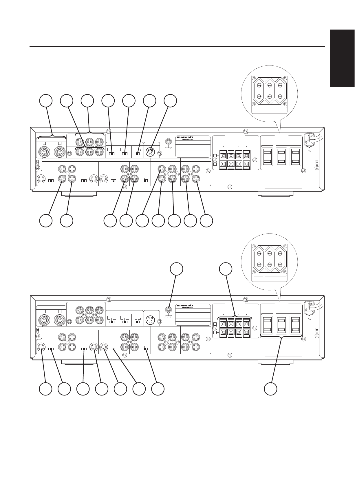
后面板
DVDaudioinputjacksDVD 声音输入插孔
q
将 DVD 设备的输出插孔连接至这些插孔。
CDaudioinputjacksCD 音频输入插孔
w
将 CD 机的输出插孔连接至这些插孔。
AUXaudioinputjacks 辅助音频输入插孔
e
r
将 CD 机、VCR 等的输出插孔连接至这些插孔。
BGMaudioinputjacks 背景音乐输入插孔
将背景音乐功能的输出插孔连接至这些插孔。
Page 8

6
中文
SUBWOOFER jack withlow-pass filter 带低通滤波
t
器的重低音扬声器插孔
直接连接重低音扬声器的输入插孔。该插孔通过
低通滤波器输出单声道信号。
SUBWOOFER jackwithoutlow-passfilter 不带低通
y
滤波器的重低音扬声器插孔
连接 带低通滤波器的 重低音扬声器的输入插孔。
该插孔直接输出单声道信号。
PREoutputjacks 前级输出插孔
u
将扩充功率放大器的输入插孔连接至这插孔。
MUSICEFECTORinputjacks 音效器输入插孔
i
将扩充音效器的输出插孔连接至这插孔。
MUSICEFECTORoutputjacks 音效器输出插孔
o
将扩充音效器的输入插孔连接至这插孔。
EXTREMOTESENSORinputjack 外部遥感器输入插孔
!0
将外部遥感器的输入插孔连接至这插孔。
AUXMODEAUTOSELECTORSwitch 辅助模式自动
!1
选择开关 KARAOKE/BGM 卡拉 OK/ 背景音乐
AUX, KARAOKE BGM 选择开关可以用来选
择自保持状态或非自保持状态。将这些开关设在
KARAOKE 位置为自保持状态;将这些开关设在
BGM 位置为非自保持状态。
KARAOKE: 即使输入卡拉 OK 信号或 DVD 信号,
AUX 功 能 也 不 转 换 到 卡 拉 OK 或
DVD。
BGM: 输入卡拉 OK 和 DV D 信号时,AUX
功能转换到卡拉 OK 和 DVD。
CDAUTOSELECTORSwitchCD 自动选择开关
!2
此开关将选择由自动音像转换功能检测到的信号
类型,以转换输入功能。
AUDIO: 根据音频信号转换
A&V: 根据音频或视频信号转换
VIDEO: 根据视频信号转换
DVDAUTOSELECTORSwitchDVD 自动选择开关
!3
此开关将选择由自动音像转换功能检测到的信号
类型,以转换输入功能。
AUDIO: 根据音频信号转换
A&V: 根据音频或视频信号转换
VIDEO: 根据视频信号转换
VIDEOINPUT 视频输入
!4
将本输出插孔与监视器的视频输出连接。
VIDEOOUTPUT 视频输出
!5
将本输入插孔与 DVD CD 机或摄像机等的视频输
出连接。
MICINPUTjacks 麦克风输入插孔 (A/B)
!6
这些插孔用于连接麦克风。A 插孔连接到与前面
板上 MIC INPUT 1 插孔和 B 插孔连接到与前面板
上 MIC INPUT 2 插孔相同的电路。
DVDINPUTLEVELControlDVD 输入强度控制装置
!7
调节此控制装置以平衡 D VD 输入相对其他输入的
强度。
DVDSENSITIVITYSwitchDVD 灵敏度开关
!8
此开关是设定卡拉 OK 音频信号检测以及输入功
能自动转换至卡拉 OK 源的灵敏度水准。
LOW: 即使在 DVD 再生结束后,功能也不转
换至背景音乐或其他功能的场合。
MIDDLE: 通常设定在此处。
HIGH: DVD 再生过程中,功能被转换至其他功
能的场合。
CDSENSITIVITYSwitchCD 灵敏度开关
!9
此开关是设定 CD 音频信号检测以及输入功能自动
转换至 CD 源的灵敏度水准。
LOW: 即使在 CD 再生结束后,功能也不转换
至背景音乐或其他功能的场合。
MIDDLE: 通常设定在此处。
HIGH: CD 再生过程中,功能被转换至其他功
能的场合。
Page 9

7
中文
CDINPUTLEVELControlCD 输入强度控制装置
@0
调节此控制装置以平衡 CD 输入相对于其他输入的
强度。
AUXINPUTLEVELControl辅助输入强度控制装置
@1
调节此控制装置以平衡辅助输入相对于其他输入
的强度。
AUXSENSITIVITYSwitch 辅助灵敏度开关
@2
此开关是设定辅助音频信号检测以及输入功能自
动转换至辅助源的灵敏度水准。
LOW: 即使在辅助源再生结束后,功能也不转
换至背景音乐或其他功能的场合。
MIDDLE: 通常设定在此处。
HIGH: 辅助源再生过程中,功能被转换至其他
功能的场合。
BGM MONO/STEREO Switch 背景音乐单声道 / 立体
@3
声开关
选择此开关改变背景音乐的单声道或立体声。
ACOUTLETS 交流输出
@4
将此插头插入墙上的交流输出插孔。
SWITCHED 转换(最大总功耗:100W)
本机前面板上的电源开关设为 ON 或 OFF 时,打
开或关闭连接于本机的部件(部件的电源开关设
为 ON)的电源。
UNSWITCHED 不转换(最大总功耗:200W)
无论本机前面板上的电源开关设定如何,电源始
终通过 这些输出插 孔供给。( 在这种情况 下,所
连接部件的电源要用各部件的电源开关打开和关
闭。)
注意: 不要将非系统部件(例如电视机)连接到
这些交流输出插孔。
SPEAKERSYSTEMTerminals 扬声器系统终端
@5
将扬声器系统与这些插孔连接。
SIGNALGROUNDTerminal 信号接地终端
@6
接地线必须接地以减少触电的危险。
Page 10
8
中文
2
1
R
LL
R
WITH
LOW PASS
FILTER
SUB WOOFER
AUDIO OUTPUT
L
R
PRE
OUT
L
R
IN
MUSIC EFFECTOR
BGMAUX
AUDIO INPUT
DVD CD
R
L
R
L
AUTO SELECTOR MODE
SIGNAL
GROUND
B
MIC INPUT
VIDEO
INPUT
1
BGVCDDVD
32
VIDEO
OUTPUT
SPEAKER SYSTEMS
A
SPEAKER IMPEDANCE
SYSTEM C : 4 - 8 OHMS / SYSTEM A : 4-8 OHMS
SYSTEM C AND A :8-16 OHMS
+L––R+
MAX
L
SENSITIVITY
M H L
SENSITIVITY
M HL
SENSITIVITY
M H
MONO
STEREO
MIN
INPUT LEVEL
BGM
KARAOKE
A&V A&V
CDDVD AUX MODE
AUDIO
1
SERIAL NO.
MZK58
2
VIDEO
REMOTE IN
MAXMIN
INPUT LEVEL
MAXMIN
INPUT LEVEL
开关插头
最大 100W
无开关插头
最大 200W
交 流 输 出
AUDIO VIDEO
AC OUTLETS
SAME AS LINE VOLTAGE
SWITCHED
MAX 100W
UNSWITCHED
MAX 200W
中国版本
新加坡/马来西亚版本
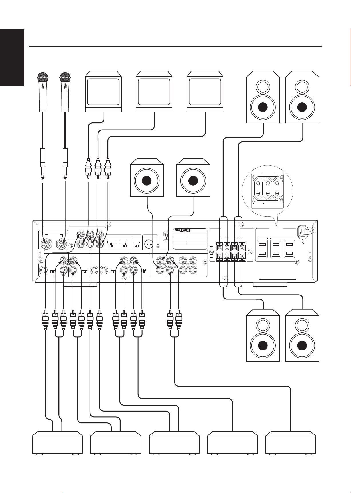
系统的连接
麦克风
MIC
麦克风
MIC
显示器
Monitor TV
显示器
Monitor TV
系统 2
有源重低音扬声器
显示器
Monitor TV
系统 1
有源重低音扬声器
右
系统 1
左
右 左
系统 2
DVD 机 CD 机 录像机或 LD 机 背景音乐 功率放大器
Page 11
9
中文
连接方法
15mm
+
+
−
R L
−
SPEAKER SYSTEMS
1
2
HOT COLD GND
HOT
COLD
GND
HOT
GND
HOT
GND
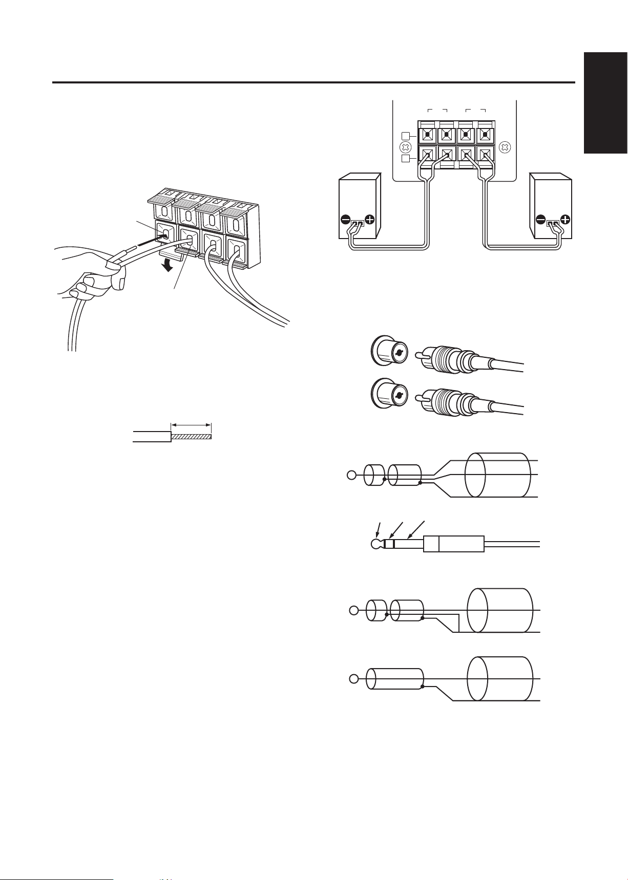
扬声器导线的连接
(1) 按箭头所指方向按下拉杆,将导线插入孔穴的内
部。
(2) 返回拉杆至原处以固定导线。
(+)导线至(+)接线端
(-)导线至(-)接线端
在连接之前,用钳子等剥去各导线顶端约 15mm 长的
被覆。
左扬声器右扬声器
连接 RCA 插头
在连接 RCA 插头时,必须注意将红色插头插入红色插
孔而将白色插头插入白色插孔。
左
白
右
白
红
红
连接至平衡输入端
注意 : 请注意从扬声器插孔露出的导线不要与其他导线接
触。另外,若与其他扬声器导线接触,可能会导致
本机故障。
可以与其连接的扬声器系统的阻抗。
一个系统所使用的扬声器。(1 或 2)
................................................... 4 Ω 到 16 Ω
二个系统所使用的扬声器。(1 和 2)
...................................................8 Ω 到 16 Ω
连接至非平衡输入端
或
Page 12
10
中文
扬声器连接的重要注意事项
+
+
+
+
6767
+
+
+
+
67
67
1. MZK58 的最大输出为 150 W+150 W。因此,需要
最大输出为 150 W 或 150 W 以上的扬声器。
2. MZK58 的最小扬声器阻抗的设计值为 4 Ω。如果
两个 6 Ω 的扬声器系统并联,其阻抗将超过设计值,
因此保护装置将起作用。
当使用两个扬声器系统且保护装置频繁起作用时,
此时您应该将扬声器系统串联。
3. 使用 Marantz 原装扬声器可以防止因误匹配而引起
的任何问题或损坏。
并联
q
(每个扬声器的阻抗应为 8 Ω 或 8 Ω 以上)
6Ω+6Ω → 3Ω
(NG : < 4Ω)
串联
w
(总共 :超过 4 Ω,可用)
6Ω+6Ω = 12Ω
(OK : > 4Ω)
Page 13
11
中文
音像转换原理
DVD
CD
BGV
MIC 1
MIC A
MIC 2
MIC B
MIC 3
CD
AUX
BGM
DVD
BGV
CD
AUX
CD
DVD
DVD
BGM
AUX
CD
DVD
BGM
AUX
VIDEO
INPUTS
MIC
INPUTS
AUDIO
INPUTS
VIDEO 1
VIDEO 2
VIDEO 3
VIDEO
OUTPUTS
MIC VOL. 1/A
MIC VOL. 2/B
MIC VOL. 3
MIC MASTER VOL.
SPEAKER OUTPUTS
PRE-OUT
MUSIC VOL.
自动音像选择
●
本功放机能检测音频和(或)视频信号,并以 1)
DVD、2)CD、3)AUX、4)BGM 的优先顺序自动
转换输入功能。
●
为了转换至 DVD、CD 和 A UX,本功放机能够对导
致输入功能转换的各类信号(音频、视频、音频和
视频)作出选择。
AUDIO : 根据音频信号转换
A & V : 根据音频或视频信号转换
VIDEO : 根据视频信号转换
●
使用 AUX 和 TAPE, KARAOKE BGM 选择开关
可用来选择自保持或非自保持状态。将这些开关设
在 K ARAOKE 位置为自保持状态;将这些开关设在
BGM 位置为非自保持状态。
KARAOKE : 即使输入 DVD 或 CD 信号,AUX 功能
也不转换到 DVD 或 CD。
BGM : 输入 DVD 或 CD 信号时,AUX 功能转
换到 DVD 或 CD。
Page 14

12
中文
遥控功能
CONTROL
KEY
ECHO MIC MUSIC
#5
#4
#3
#2
#11
2
3
4
5
#66
RC58MZK
1
2
4
3
30o
30o
OF
F
ON
OFF
ON
MUSI
C VOLUME
BASS BOOS
T
DV
D
OFF
O
N
W
ER
MAX
MI
C MASTER VOLU
ME
MAX
ON
OFF
F. B EQ
CD
AUX
BGM
1
/
A
DELAY
REPEAT
TREBLE
MID
BASS
T
REBL
E
MI
D
BA
S
S
2/B
3
1
2
NP
UT
3
M
IC VO
L
M
IC 3 ECHO
ECHO
MI
C
MUSIC
B
GM
BALANCE
R
ECHO VO
LUME
MAX
KARA
OKE DIGITAL
AMPLIFIER
MZK58
♭
6
♭
5
♭
4
♭
3
♭
2
♭
1
♯
1
♯
2
♯
3
♯
4
♯
5
♯
6
KEY CONTROL
部件名称及其功能
主调变换按钮
q
●
上升(#1 至 #6)
主调能够以 6 档、每档半个音调从标准主调上升 2.5 个音调;
●
标准( )
按此按钮回复至标准主调;
●
下降(♭1 至♭6)
主调能够以 6 档、每档半个音调从标准主调下降 2.5 个音调;
(一曲结束后,音调自动回复至标准主调)
音乐音量控制按钮
w
●
按其中一个按钮以提高或降低音乐音量。在调节过程中,本
体上的音乐音量控制装置的发光二极管会闪烁。间歇地按
下按钮才能得到良好的微调。
麦克风主音量控制按钮
e
●
按其中一个按钮以提高或降低麦克风的整体音量。在调节
过程中,本体上的麦克风主音量控制装置的发光二极管会
闪烁。间歇地按下按钮才能得到良好的微调。
主回音强度控制按钮
r
●
按其中一个按钮以提高或降低回音量。
遥控器的操作
1. 无线遥控装置
无线遥控器与放大器上的传感器之间的距离不能超
过 5 米。注意,如果遥控器没有对准传感器或在两
者之间存在障碍时,遥控器将不起作用。
2. 安装电池
在正常使用情况下遥控器中的电池寿命约为半年。
如果长期不使用遥控器时,请取出电池。当电池的
电力变弱时,请尽早更换。
不正当地使用电池可能导致漏电和电池破裂。
注意下列事项:
⑴ 装入电池时注意电池的正极(+)和负极(-)
的方向与电池槽内所指示的一致;
⑵ 不要将新旧电池混用;
⑶ 即使是用同样外型的电池,由于型号不同,电
池的电压有所不同。注意不要将不同型号的电
池混用;
⑷ 勿将已使用过的电池作为可燃垃圾处理。
电池 ×2
反面
约 5m
遥控器
电池盖
Page 15

13
中文
一般操作
OFFON
OFFON
MUSIC VOLUME
BASS BOOST
DVD
OFFON
POWER
MIN MAX
MIC MASTER VOLUME
MIN MAX
ONOFF
F. B EQ
CD AUX BGM
1/A
DELAYREPEATTREBLEMIDBASSTREBLEMIDBASS
2/B 3 1 2
MIC INPUT
3
MIC VOLMIC 3 ECHO
ECHOMICMUSICBGM
BALANCE
RL
ECHO VOLUME
MAXMIN
KARAOKE DIGITAL AMPLIFIER MZK58
♭6♭5♭4♭3♭2♭
1
♯1♯2♯3♯4♯5♯
6
KEY CONTROL
2 5 1
43
6
1 连接所需的麦克风。
2 接通放大器及其他组件的电源
。
3 再生卡拉 OK 音乐源组件,并用音乐音量控制装置
调节音量。
4 用麦克风音量控制装置和麦克风主音量控制装置调
节各麦克风音量之间的平衡以及麦克风整体音量与
音量之间的平衡。
5 用主回音音量控制装置调节回音强度。
6 用数字式主调控制器按钮设定所需的音调。
正确使用麦克风的注意事项
●
使用麦 克风时必须使麦克风与口部之间保持 5 〜
10cm 的距离。
●
为保证声音清晰,所握的地方要与麦克风头部留有
一定的间隙。
●
不要阻碍风挡的底部,这会妨碍正确的声音再生,
使低音不清晰,并且容易产生啸声。
与口部保持约 5 〜 10cm 距离
与麦克风头部保留一定的间隙
Page 16

14
中文
要将音量旋钮停在所需位置
顺时针转动音乐旋钮或麦克风旋钮,购机时这些旋钮
停在“10”处。这一设置可以按如下所述改动:
1 从 MZK58 上拆下音量旋钮。
2 拧下音量旋钮上的螺丝。
购机时,停止器设置如下:
音量旋钮可以从 0 转到 10。
3 从音量旋钮上拆下停止器,然
后按下图进行设置。
4 拧紧螺丝,然后将旋钮装回到
MZK58 上。
设置示例
前面板侧
内部
停止位置设在
3 和 4 之间。
停止位置设
在中间。
2
3
停止位置设在
6 和 7 之间。
保养注意事项
当本体表面有污秽时,请用干的软布擦拭干净。在极
为污秽的情况下,用软布沾上稀释了 5.6 倍的洗涤精
后拧干,除去污秽后再用干布擦拭。切勿使用酒精、
稀释剂、苯、杀虫剂或是其他挥发性溶剂,因为这会
有损本体表面涂层或失去光泽。也勿用含有化学药品
的布料擦拭本体或长时间遗放在本体上,这会使表面
处理品质下降或涂层剥落。
Page 17

15
中文
故障的排除
很多场合,由于操作失误引起功放机出错。按照下列
检查方法,用户可以轻而易举地纠正许多错误。
症状 原因 措施
扬声器无音响输出 1. 电源处于关闭状态;
2. 电源线脱落;
3. 音乐音量控制装置设定在最小值。
其中一个扬声器无音响 1. BALANCE 控制装置完全偏于一个极端位置;
2. 未连接某一扬声器导线;
麦克风无音响输出 1. 麦克风插头未被完全插入插孔;
2. 麦克风开关处于关闭状态;
3. 相对应的麦克风音量控制装置或麦克风主音量控
制装置处于最小值状态;
4. 麦克风离口部太远或是麦克风的握持方法不正确;
售后服务
如果发现本机有毛病,当地的经销商会按您的要
q
求收费修理或更换有毛病的零件。
在要求当地的经销商进行修理之前,请先参阅“故
w
障的排除”一节,并再次检查。
致经销商:
如果您的客户要求您为他进行售后服务,请先检查以
下内容。
●
确认故障的细节。
●
检查所有的电缆和连接。
●
为客户讲解使用本系统 的操作注意事项 和使用说
明。
如果发现本机有毛病,且不能修理,请将有毛病的机
器送到最近的 Marantz 授权服务中心。
1. 打开电源;
2. 将电源线稳固地插入电源插座;
3. 调节音乐音量控制装置;
1. 将控制装置设定于中间位置;
2. 将导线稳固地插入接线端;
1. 将插头稳固地插入插孔;
2. 打开麦克风开关;
3. 调节控制装置;
4. 参照有关麦克风的使用说明;
使用礼仪
用户所喜爱的卡拉 OK 娱乐活动也许正在打扰别人。进行卡拉 O K 时,也请考虑到周围的
近邻。卡拉 O K 的音量是由用户决定的,记住即使是很小的声音在宁静的夜晚也能传得
很远,在夜间进行卡拉 OK 时请特别留意。建议用户关上窗户以免声音外漏至近邻,并
且要为他人的舒适生活环境着想。
Page 18

中文
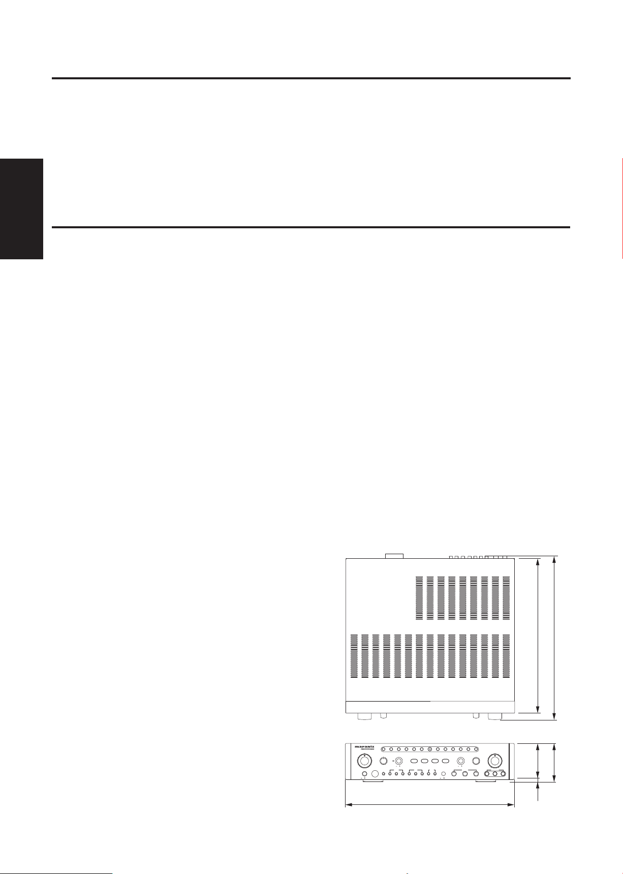
420
6 90
96
381.5
410
OFFON
OFFON
MUSIC VOLUME
BASS BOOST
DVD
OFFON
POWER
MIN MAX
MIC MASTER VOLUME
MIN MAX
ONOFF
F. B EQ
CD AUX BGM
1/A
DELAYREPEATTREBLEMIDBASSTREBLEMIDBASS
2/B 3 1 2
MIC INPUT
3
MIC VOLMIC 3 ECHO
ECHOMICMUSICBGM
BALANCE
RL
ECHO VOLUME
MAXMIN
KARAOKE DIGITAL AMPLIFIER
MZK58
♭6♭5♭4♭3♭2♭1♯1♯2♯3♯4♯5♯
6
KEY CONTROL
版权
●
广播、音源(如录制的音乐磁带)、DVD、录像带、
CD 等受版权法严格保护。
技术规格
功放机
最大输出(1kHz,8Ω) ..........................................150W+150W
总谐调失真..............................................................................0.05%
(1kHz, 70W, 8Ω)
音频输入插孔(灵敏度/阻抗)
DVD、CD、AUX ............................................150mV/27KΩ
BGM .....................................................................450mV/27KΩ
EFFECTOR .........................................................150mV/27KΩ
MIC ...........................................................................4.3mV/5KΩ
音频输出插孔(输出强度/输出阻抗)
PRE ......................................................................... 800mV/1KΩ
EFFECTOR ........................................................... 180mV/1KΩ
SUBWOOFER ...................................................... 800mV/1KΩ
频率响应
MUSIC .............................................20Hz to 15kHz, +4/-2dB
MIC ...................................................40Hz to 15kHz, +4/-2dB
音质控制特性
MUSIC BASS ..................................+13/-10dB(100Hz)
MID .......................................
TREBLE ................................+13/-9dB(10kHz)
MIC BASS ........................................±12dB(100Hz)
MID ............................................. ±13dB(1kHz)
TREBLE ................................+11/-8dB(10kHz)
扬声器阻抗.............................................................. 4 Ω 到 16 Ω
(一个系统所使用 1 或 2)
8 Ω 到 16 Ω
(二个系统所使用 1 和 2)
音调控制范围...............................................13 步 , ±3 个音调
视频输入插孔
(灵敏度/输入阻抗) .......................................1Vp-p/75Ω
视频输出插孔
(灵敏度/输出阻抗) .......................................
+12/-13dB(1kHz)
1Vp-p/75Ω
●
这些资源除用于自己欣赏外,为商业用途而使用、
经销、租借这些音源,或将复制的媒体销售给他人,
都需要有版权拥有者的许可。
电源
电源电压
新加坡 / 马来西亚版本 ................AC 230 - 240V 50Hz
中国版本 ......................................................... AC 220V 50Hz
功率消耗
(IEC 60065)
新加坡 / 马来西亚版本 ........................................140W
中国版本 .....................................................................130W
( 待机 ) ....................................................................................30W
交流输出
UNSWITCHED(最大总功耗:200W) ...........................
2
SWITCHED(最大总功耗:100W)..................................1
尺寸(宽 × 高 × 深) ...............420mm×96mm×410mm
重量 .............................................................................. 毛重 9.3Kg
附属品
使用说明书.........................................................................................1
无线遥控器(RC58MZK) ............................................................1
电池(AAA) ............................................................................... 2支
针标签...................................................................................................1
●
由于改进的关系,以上的规格和外观会不经予告而
有所变更。
尺寸(mm)
16
Page 19

English
Thank you for your purchase of the MZK58 Digital Echo AV Amplifier.
Before using the Digital Echo AV Amplifier, be sure to read this entire operating manual so that
you can take full advantage of the MZK58’s features.
After you finish reading, keep this document and the warranty handy in a safe place in case you
need them in the future. The manual should be very helpful in understanding the microphone re-
ceiver and solving any difficulties that may arise during use.
SPECIAL FEATURES
● Power output 150 W + 150 W
(8 ohms 10% THD)
● 4 Line inputs Auto function in order of priority.
● Built-in high quality digital echo.
● 5 microphones simultaneously available.
● Built-in key controlle allows to be transposed
the key of music over 3 tones, in ±6 positions.
(Automatically resets after use)
● Bass Boost Function
● Wireless remote controller
(Control music level, Microphone level,
Key controller)
Table of Contents
WARNING ................................................................................................................ 1
SAFETY PRECAUTIONS ......................................................................................... 1
HANDLING PRECAUTIONS .................................................................................... 2
BEFORE CONNECTING ......................................................................................... 2
NAMES OF PARTS AND THEIR FUNCTIONS ........................................................ 3
SYSTEM CONNECTIONS ....................................................................................... 8
CONNECTIONS ....................................................................................................... 9
PRINCIPLE OF AUDIO VIDEO SWITCHOVER .............................................. 11
AUTOMATIC AUDIO VIDEO SWITCHING ...................................................... 11
REMOTE CONTROL .............................................................................................. 12
GENERAL OPERATION ........................................................................................ 13
TO STOP THE VOLUME KNOB IN THE DESIRED POSITION ............................. 14
MAINTENANCE ..................................................................................................... 14
TROUBLESHOOTING ........................................................................................... 15
AFTER-SALES SERVICING .................................................................................. 15
ETIQUETTE OF SOUND ....................................................................................... 15
COPYRIGHT .......................................................................................................... 16
SPECIFICATIONS .................................................................................................. 16
Page 20

WARNING
NO!
OFFON
OFFON
MUSIC VOLUME
BASS BOOST
DVD
OFFON
POWER
MIN MAX
MIC MASTER VOLUME
MIN MAX
ONOFF
F. B EQ
CD AUX BGM
1/A
DELAYREPEATTREBLEMIDBASSTREBLEMIDBASS
2/B 3 1 2
MIC INPUT3MIC VOLMIC 3 ECHO
ECHOMICMUSICBGM
BALANCE
RL
ECHO VOLUME
MAXMIN
KARAOKE DIGITAL AMPLIFIER
MZK58
♭6♭5♭4♭3♭2♭1♯1♯2♯3♯4♯5♯
6
KEY CONTROL
: :
@
.
rackMZK58
leg leg
- Do not expose the equipment to rain or moisture.
- Do not place anything closer than 0.1 meters above the top
- Do not remove the cover from the equipment.
- Do not insert anything into the equipment through the ventilation holes.
- Ensure a space of about 0.1 meters is left around the unit.
- No objects filled with liquid, such as vases, should be placed
- Do not handle the mains lead with wet hands.
- Do not cover the ventilation with any items such as table-
- When the switch is in the OFF position, the equipment is not
cloths, newspapers, curtains, etc.
- No sources of naked flame, such as lit candles, should be
- To completely disconnect this product from the mains, dis-
placed on the equipment.
- When disposing of used batteries, please comply with gov-
- The mains plug is used to completely interrupt the power supernmental regulations or applicable public environmental
rules for your country or region.
SAFETY PRECAUTIONS
In case of abnormality.
In case any abnormal noise or smell is generated from the
unit during use, immediately switch the power off, unplug the
power cord from the power outlet, and consult your dealer or
an authorized service center for a check-up.
Do not open the unit.
panel.
on the unit.
completely disconnected from the MAINS.
connect the plug from the wall socket outlet.
ply to the unit and must be within easy access by the user.
Keep away from water and foreign objects.
Do not insert or drop metallic objects, such as hairpins,
nails and coins, or flammable objects, such as paper and
matches, through the ventilation holes or other openings on
the unit, for this will cause a malfunction or fire hazard and
electric shock. In case water or a foreign object enters the
unit, consult an authorized service center or your dealer for
a check-up.
English
High-voltage components are used inside the unit. Do not
open the cabinet to check or modify the unit, for this involves
a risk of electric shock. Any deterioration in performance or
malfunction caused by user modification will be excluded
from the warranty.
Do not exceed the maximum power capacity.
The components equipped with the rear panel AC OUTLETS
accept connections from other stereo system components.
However, do not connect components for which the total power
consumption exceeds the power capacity marked on the rear
panel, for this may cause malfunction or fire hazard. Also note
that components through which a large current flows when the
power is switched on, such as a TV set, cannot be connected
to such an AC outlet unless it has been designed to accept
TV connections.
Do not damage the power cord.
Hold the power plug when plugging or unplugging the power
cord. Do not pull the cord or touch it with wet hands, for this
may cause a short circuit or electrical hazard. Do not leave
the power cord under this unit, or under furniture, or between
objects. Also, never tie the power cord with another cord,
knot it, or leave it in a place exposed to high human traffic.
When the unit is unused for extended periods...
When leaving home for an extended period, for example
when going on a trip, set the power switch to off and unplug
the power plug from the power outlet for safety. This will prevent fire hazard due to unexpected accidents with the unit.
Appliance with ventilation openings
The following rack size measurements must be adhered to:
q Between the R/L side of MZK58 and R/L sides of the rack;
more than 5 cm
w Between the upper side of MZK58 and the rack; more than
10 cm
e The rear of the rack must be opened.
※ Do not remove the legs.
These openings must not be blocked or covered. If this is done
accidentally, the internal temperature will rise, and cause a fire.
There are ventilation openings on the upper and lower sections
of the casing to prevent overheating.
1
Page 21

2
English
HANDLING PRECAUTIONS
Do not install the unit in the following locations:
●
In places exposed to direct sunlight or near heat
sources, such as a radiator.
●
In places where the heat cannot escape due to
poor ventilation, or which are very humid or dusty.
●
In unstable places, with sloping surfaces or exposed
to excessive vibration.
BEFORE CONNECTING
●
In places which may be exposed to rain, such as
near a window.
●
In places which may be exposed to soot, vapor or
heat, such as near cooking facilities.
Connection precautions
●
Be sure to switch off the power of the relevant
equipment before making any connection.
●
The “White” input/output Jacks of the amplifier are
designed for the Left channel, while the “red” input/
output jacks are for the Right channels. Be sure
to connect the cords without mistaking the color
codes for the left and right channels.
●
Insert the plugs of the connection cords securely
into the jacks. If the connection is incomplete,
there may be no sound produced or noise may be
generated.
●
When unplugging the power cord from the outlet,
be sure to hold the plastic molding of the plug itself
and pull.
Power consumption of AC power outlets
●
Be careful that the total power consumption does
not exceed the wattage marked on the rear panel.
Do not connect appliances other than system
components to the power outlets of this unit.
●
Do not connect a TV set to this unit; even if it
indicates a power consumption value below the
permissible value when the TV power is turned on.
Page 22

3
English
NAMES OF PARTS AND THEIR FUNCTIONS
OFFON
OFFON
MUSIC VOLUME
BASS BOOST
DVD
OFFON
POWER
MIN MAX
MIC MASTER VOLUME
MIN MAX
ONOFF
F. B EQ
CD AUX BGM
1/A
DELAYREPEATTREBLEMIDBASSTREBLEMIDBASS
2/B 3 1 2
MIC INPUT
3
MIC VOLMIC 3 ECHO
ECHOMICMUSICBGM
BALANCE
RL
ECHO VOLUME
MAXMIN
KARAOKE DIGITAL AMPLIFIER MZK58
♭6♭5♭4♭3♭2♭
1
♯1♯2♯3♯4♯5♯
6
KEY CONTROL
1 2 3 4 5 6 7 8 9 10
18 17 16 15 14 13 12 11
[ FRONT PANEL SIDE ]
q POWER Switch (ON /OFF )
Press this switch to turn the power ON, and again
u ECHO DELAY
Adjust the delay time with this control.
to turn the power OFF.
i MIC 3 ECHO ON/OFF Switch
w REMOTE SENSOR
This is the IR sensor, which receives signals
from the wireless remote control unit supplied
(RC58MZK).
e BGM INPUT LEVEL Control
Adjust this control to optimize the BGM input
level.
Please note: The BGM level cannot be adjusted
using the MUSIC VOL control on the front panel.
r MUSIC TONE Controls (BASS/ MID/ TREBLE)
These controls are used to boost or reduce the
(low, middle, or high) frequency response of
music.
Press this switch to turn the MIC 3 ECHO ON, and
again to turn it OFF.
o MIC VOL Controls (1/A, 2/B, 3)
These controls adjust the microphone input level
from the MIC INPUT 1/ 2/ 3 jack (front panel) and
MIC INPUT A/ B jack (rear panel).
!0 MIC INPUT Jacks (1, 2, 3)
Those jacks are for connecting microphones.
!1 MIC MASTER VOL Control
This control adjusts the overall volume of all
microphones.
!2 ECHO VOL Control
t MIC TONE Controls (BASS/ MID/ TREBLE)
These controls are used to boost or reduce the
(low, middle, or high) frequency response of
microphones.
y ECHO REPEAT
Adjust the interval of repetitions with this control.
This control affects the echo amount mixed into
the microphone inputs to the MIC INPUT 1, 2 and
3 jacks and MIC INPUT A and B jacks.
!3 F.B EQ Switch
Pre s s thi s sw itch to tur n the FEEDBACK
EQUALIZER function ON, and again to turn it
OFF.
Page 23

4
English
!4 DIGITAL KEY Control Buttons
Press the required button to transpose the key
of the music played. The key can be changed
in halftone steps for six steps; either higher or
lower.
The key returns to the default level once the tune
has finished.
!5 FUNCTION DISPLAY
Th is disp lay indic ates th e currently active
function/s.
!6 BASS BOOST Switch and DISPLAY
Press this switch to turn the BASS BOOST ON,
and again to turn it OFF.
The display indicates green when this switch is
turned on.
!7 BALANCE VOL Control
With this control you can adjust the volume
balance between the left and right channels.
!8 MUSIC VOL Control
This control allows you to adjust the volume of the
musical source.
(The Volume of the BGM is controlled from inside
the ceiling panel.)
Page 24

5
English
2
1
R
LL
R
WITH
LOW PASS
FILTER
SUB WOOFER
AUDIO OUTPUT
L
R
PRE
OUT
L
R
IN
MUSIC EFFECTOR
BGMAUX
AUDIO INPUT
DVD CD
R
L
R
L
AUTO SELECTOR MODE
SIGNAL
GROUND
B
MIC INPUT
VIDEO
INPUT
1
BGVCDDVD
32
VIDEO
OUTPUT
SPEAKER SYSTEMS
A
SPEAKER IMPEDANCE
SYSTEM C : 4 - 8 OHMS / SYSTEM A : 4-8 OHMS
SYSTEM C AND A :8-16 OHMS
+L––R+
MAX
L
SENSITIVITY
M H L
SENSITIVITY
M HL
SENSITIVITY
M H
MONO
STEREO
MIN
INPUT LEVEL
BGM
KARAOKE
A&V A&V
CDDVD AUX MODE
AUDIO
1
SERIAL NO.
MZK58
2
VIDEO
REMOTE IN
MAXMIN
INPUT LEVEL
MAXMIN
INPUT LEVEL
AUDIO VIDEO
开关插头
最大 100W
无开关插头
最大 200W
交 流 输 出
1 2 3 4 5 6
16 1415 13 12 11 10
7 8 9
AC OUTLETS
SAME AS LINE VOLTAGE
SWITCHED
MAX 100W
UNSWITCHED
MAX 200W
China Version
Singapore,
Malaysia Version
2
1
R
LL
R
WITH
LOW PASS
FILTER
SUB WOOFER
AUDIO OUTPUT
L
R
PRE
OUT
L
R
IN
MUSIC EFFECTOR
BGMAUX
AUDIO INPUT
DVD CD
R
L
R
L
AUTO SELECTOR MODE
SIGNAL
GROUND
B
MIC INPUT
VIDEO
INPUT
1
BGVCDDVD
32
VIDEO
OUTPUT
SPEAKER SYSTEMS
A
SPEAKER IMPEDANCE
SYSTEM C : 4 - 8 OHMS / SYSTEM A : 4-8 OHMS
SYSTEM C AND A :8-16 OHMS
+L––R+
MAX
L
SENSITIVITY
M H L
SENSITIVITY
M HL
SENSITIVITY
M H
MONO
STEREO
MIN
INPUT LEVEL
BGM
KARAOKE
A&V A&V
CDDVD AUX MODE
AUDIO
1
SERIAL NO.
MZK58
2
VIDEO
REMOTE IN
MAXMIN
INPUT LEVEL
MAXMIN
INPUT LEVEL
AUDIO VIDEO
开关插头
最大 100W
无开关插头
最大 200W
交 流 输 出
17 18 19 20 21 22
26 25
2423
AC OUTLETS
SAME AS LINE VOLTAGE
SWITCHED
MAX 100W
UNSWITCHED
MAX 200W
China Version
Singapore,
Malaysia Version
[ REAR PANEL SIDE ]
q DVD audio input jacks
Connect the output jacks of DVD Equipment to
these jacks.
w CD audio input jacks
Connect the output jacks of CD player to these
jacks.
Page 25

6
English
e AUX audio input jacks
Connect the output jacks of a CD player, VCR etc.
to these jacks.
r BGM audio input jacks
Connect the output jacks of the BGM function to
these jacks.
t SUB WOOFER jack with low-pass filter
Connect the input jack of the subwoofer directly.
This jack outputs the monaural signal through a
low-pass filter.
y SUB WOOFER jack without low-pass filter
Connect the input jack of the subwoofer with a
low-pass filter.
This jack transmits the monaural signal directly.
u PRE output jacks
Connect the input jacks of the extension Power
amplifier to these jacks.
i MUSIC EFFECTOR input jacks
Connect the output jacks of the music effector
extension to these jacks.
o MUSIC EFFECTOR output jacks
Connect the input jacks of the music effector
extension to these jacks.
!0 EXT. REMOTE SENSOR input jack
This Jack inputs the external remote control
signal.
!1 AUX MODE AUTO SELECTOR Switch
KARAOKE/BGM
With AUX, KARAOKE BGM selector switches
can be used to select self-holding or non selfholding
status. The self-holding status is set by setting the
switches to the KARAOKE position; the non self-
holding status is set by setting the switches to the
BGM position.
KARAOKE : The AUX function does not switch to
DVD or CD even when a DVD or CD
signal is input.
BGM : The AUX function switches to DVD
or CD when a DVD or CD signal is
input.
!2 CD AUTO SELECTOR Switch
This switch selects the types of signals detected
by the automatic audio/video switChinag function
to switch the input function.
AUDIO : SwitChinag based on audio signal.
A & V : SwitChinag based on either audio or
video signals.
VIDEO : SwitChinag based on video signal.
!3 DVD AUTO SELECTOR Switch
This switch selects the types of signals detected
by the automatic audio/video switChinag function
to switch the input function.
AUDIO : SwitChinag based on audio signal.
A & V : SwitChinag based on either audio or
video signals.
VIDEO : SwitChinag based on video signal.
!4 VIDEO input jacks
Connect this output jack with the video input of
the monitor.
!5 VIDEO output jacks
Connect this input jack with the video output of a
DVD CD BGV player or video camera, etc.
!6 MIC INPUT jacks (A/B)
Those jacks are for connecting microphones.
The A jack is connected to the same circuit as
the MIC INPUT jacks 1 and 2, both on the front
panel.
Page 26

7
English
!7 DVD INPUT LEVEL Control
Adjust this control to balance the DVD input level
with respect to other input.
!8 DVD SENSITIVITY Switch
This switch sets the sensitivity level at which the
DVD audio signal is detected and the input
function switches automatically to a DVD source.
LOW : Set to this position if the function should
not switch to BGM or another function,
even after the DVD play is finished.
MIDDLE : Normally set to this position.
HIGH : Set to this position in case the function
switches to another function in the
middle of DVD play.
!9 CD SENSITIVITY Switch
This switch sets the sensitivity level at which the
CD audio signal is detected and the input function
switches automatically to a CD source.
LOW : Set to this position if the function does
not switch to BGM or another function
even after the CD play is finished.
MIDDLE : Normally set to this position.
HIGH : Set to this position in case the function
switches to another function in the
middle of CD play.
@0 CD INPUT LEVEL Control
Adjust this control to balance the CD input level
with respect to other inputs.
@1 AUX INPUT LEVEL Control
Adjust this control to balance the AUX input level
with respect to other inputs.
@2 AUX SENSITIVITY Switch
This switch sets the sensitivity level at which the
AUX audio signal is detected and the input function
switches automatically to an AUX source.
LOW : Set to this position if the function does
not switch to BGM or another function,
even after the AUX source play is
finished.
MIDDLE : Normally set to this position.
HIGH : Set to this position in case the function
switches to another function in the
middle of AUX source play.
@3 BGM MONO/STEREO Switch
Select this switch to switch between monaural or
stereo of BGM.
@4 AC OUTLETS
Plug this cord into an AC wall outlet.
SWITCHED (max. total power consumption:
100 W)
Whenever the POWER switch on the unit’s front
panel is set to ON or OFF, the power to the
components (whose power switch is set to ON)
connected to the unit is also switched ON or OFF.
UNSWITCHED (max. total power consumption:
200 W)
Power is permanently supplied through these
outlets, regardless of the POWER switch setting
on the unit of the front panel. (In this case, the
power of the connected component should be
turned ON and OFF using the power switch on
each component concerned.)
Note: Do not connect non system component
units to these AC outlets. For instance, do
not connect a TV monitor.
@5 SPEAKER SYSTEM Terminals
Connect speaker systems with these jacks.
@6 SIGNAL GROUND Terminal
The grounding wire shall be connected to a
grounding line to reduce the risk of electric
shock.
Page 27

8
English
SYSTEM CONNECTIONS
2
1
R
LL
R
WITH
LOW PASS
FILTER
SUB WOOFER
AUDIO OUTPUT
L
R
PRE
OUT
L
R
IN
MUSIC EFFECTOR
BGMAUX
AUDIO INPUT
DVD CD
R
L
R
L
AUTO SELECTOR MODE
SIGNAL
GROUND
B
MIC INPUT
VIDEO
INPUT
1
BGVCDDVD
32
VIDEO
OUTPUT
SPEAKER SYSTEMS
A
SPEAKER IMPEDANCE
SYSTEM C : 4 - 8 OHMS / SYSTEM A : 4-8 OHMS
SYSTEM C AND A :8-16 OHMS
+L––R+
MAX
L
SENSITIVITY
M H L
SENSITIVITY
M HL
SENSITIVITY
M H
MONO
STEREO
MIN
INPUT LEVEL
BGM
KARAOKE
A&V A&V
CDDVD AUX MODE
AUDIO
1
SERIAL NO.
MZK58
2
VIDEO
REMOTE IN
MAXMIN
INPUT LEVEL
MAXMIN
INPUT LEVEL
开关插头
最大 100W
无开关插头
最大 200W
交 流 输 出
AUDIO VIDEO
DVD Player
VTR or LD Player BGM
Power Amplifier
Right
System 2
System 1
System 2
Active Subwoofer
Left
Right
Left
Monitor TV Monitor TV Monitor TV
CD Player
System 1
Active Subwoofer
MIC MIC
AC OUTLETS
SAME AS LINE VOLTAGE
SWITCHED
MAX 100W
UNSWITCHED
MAX 200W
China Version
Singapore,
Malaysia Version
Page 28
9
English
CONNECTIONS
(+) cord to (+) terminal
(−) cord to (−) terminal
15mm
+
+
−
R L
−
Right speaker Left speaker
SPEAKER SYSTEMS
1
2
Left
Right
White
Red
White
Red
Connection of Speaker Cords
1. Push the lever in the direction of the arrow and
insert the conductor wire into the hole.
2. Return the lever to the original position to secure
the conductor wire.
Before connection, strip a section of coating about 15
mm in length from the extremity of each cord using a
tool such as a pair of pliers.
Connecting the RCA Pin Plugs
When connecting RCA pin plugs, be sure to insert the
red plug into the red jack and the white plug into the
white jack.
Caution: Be car eful th at the cor d condu ctor s
projected from a terminal do not come into
contact with those of another cord. Contact
from the conductors of different speaker
cords may cause damage to the system.
Impedance of connectable speaker systems.
The speaker system is used by one system. (1 or 2)
................................. 4 Ω to 16 Ω
The speaker system is used by two systems. (1 and 2)
................................. 8 Ω to 16 Ω
Page 29

10
English
Important Precautions for Speaker Connection
+
+
+
+
6767
+
+
+
+
67
67
1. The maximum output of the MZK58 is 150 W +
150 W. Therefore, the speakers used must have a
maximum input of 150 W or more.
2. The minimum speaker impedance of MZK58
is designated at 4-ohm. If two 6-ohm speaker
systems are connected in parallel, this will exceed
the design value and trigger a safety protector
device.
When two speaker systems are used and the
protector is frequently activated, the speaker
systems should be connected serially instead.
3. Use marantz genuine speakers to prevent any
trouble or damage caused by mismatChinag.
qParallel connection
(each speaker should be 8Ω or more)
6Ω+6Ω → 3Ω
(<4Ω : NG)
wSeries connection
(total: over 4Ω is available)
6Ω+6Ω = 12Ω
(>4Ω : OK)
Page 30

11
English
PRINCIPLE OF AUDIO VIDEO SWITCHOVER
DVD
CD
BGV
MIC 1
MIC A
MIC 2
MIC B
MIC 3
CD
AUX
BGM
DVD
BGV
CD
AUX
CD
DVD
DVD
BGM
AUX
CD
DVD
BGM
AUX
VIDEO
INPUTS
MIC
INPUTS
AUDIO
INPUTS
VIDEO 1
VIDEO 2
VIDEO 3
VIDEO
OUTPUTS
MIC VOL. 1/A
MIC VOL. 2/B
MIC VOL. 3
MIC MASTER VOL.
SPEAKER OUTPUTS
PRE-OUT
MUSIC VOL.
●
With AUX , the KARAOKE BGM selector
switches can be used to select self-holding or non
self-holding status. The self-holding status is set
by setting the switches to the KARAOKE position;
the non self-holding status is set by setting the
switches to the BGM position.
KARAOKE : The AUX function does not switch to
DVD or CD, even when a DVD or CD
signal is input.
BGM : The AUX function switches to DVD
or CD when a DVD or CD signal is
input.
AUTOMATIC AUDIO VIDEO SWITChinaG
●
This unit is capable of detecting the audio and/
or video input signals and switChinag the input
function automatically in the priority order of; 1)
DVD; 2) CD; 3) AUX; 4) BGM.
●
When switChinag to DVD, CD and AUX, it is
possible to select the types of signals (audio only,
video only, audio and video combined) as input
function switChinag.
AUDIO : SwitChinag based on the audio signal
A & V : SwitChinag based on either the audio or
VIDEO : SwitChinag based on the video signal
only.
video signals.
only.
Page 31

12
English
REMOTE CONTROL
CONTROL
KEY
ECHO MIC MUSIC
#5
#4
#3
#2
#11
2
3
4
5
#66
RC58MZK
1
2
4
3
Battery cover
AAA battery x 2
Back side
30o
30o
Remote
control unit
Approx. 5m
OF
F
ON
OFF
ON
MUSI
C VOLUME
BASS BOOS
T
DV
D
OFF
O
N
W
ER
MAX
MI
C MASTER VOLU
ME
MAX
ON
OFF
F. B EQ
CD
AUX
BGM
1
/
A
DELAY
REPEAT
TREBLE
MID
BASS
T
REBL
E
MI
D
BA
S
S
2/B
3
1
2
NP
UT
3
M
IC VO
L
M
IC 3 ECHO
ECHO
MI
C
MUSIC
B
GM
BALANCE
R
ECHO VO
LUME
MAX
KARA
OKE DIGITAL
AMPLIFIER
MZK58
♭
6
♭
5
♭
4
♭
3
♭
2
♭
1
♯
1
♯
2
♯
3
♯
4
♯
5
♯
6
KEY CONTROL
Names of parts and their Functions
q KEY Control Buttons
●
UPWARD (#1 to #6)
The key can be transposed up to 2.5 tones above the
standard key via 6 steps, each a half tone.
●
NATURAL ( )
Press to reset to the NATURAL key.
●
DOWNWARD (♭1 to ♭6)
The key can be transposed up to 2.5 tones below the
standard key via 6 steps, each a half tone.
(The key returns to the standard key after every tune.)
w MUSIC VOL Control Buttons
●
Press one of the buttons to increase or decrease the
music volume. The LED on the MUSIC VOL control of the
main unit blinks during the adjustment. Fine adjustment is
available by pressing the buttons intermittently.
e MIC MASTER VOL Control Buttons
●
Press one of the buttons to increase or decrease the overall
volume of the microphones. The LED on the MIC MASTER
VOL control of the main unit blinks during the adjustment.
Fine adjustment is available by pressing the buttons
intermittently.
r ECHO VOL Control Buttons
●
Press one of the buttons to increase or decrease the
amount of echo.
Operation of Wireless Remote Control Unit
1. Wireless remote control
The distance between the wireless remote control
unit and the light receptor of this unit should be less
than about 5 meters. Note that the remote control
may not operated if the light transmitter window of
the remote control unit is pointed to other direction
than the light receptor or if there is an obstacle
between the remote control unit and light receptor.
2. Loading batteries
The life of the batteries used in the remote control
unit is about half a year under normal use. If the
remote control unit is to be unused for an extended
period, remove the batteries. When the batteries
become weak, replace them earlier.
Improper use of batteries may cause a risk of
battery leakage and explosion.
Be careful to obey the following guidelines:
(1) Insert batteries so that the positive (+) and
negative (–) poles are positioned as indicated
on the battery case.
(2) Do not use old and new batteries together.
(3) Even if the shapes are the same, the voltage of
batteries may vary depending on the models.
Be careful not to use different models of
batteries together.
(4) Do not dispose of used batteries as burnable
waste.
Page 32

13
English
5 to 10 cm (2 to 4 in.) away
from your mouth.
Hold the microphone at
a certain distance from
the head.
GENERAL OPERATION
OFFON
OFFON
MUSIC VOLUME
BASS BOOST
DVD
OFFON
POWER
MIN MAX
MIC MASTER VOLUME
MIN MAX
ONOFF
F. B EQ
CD AUX BGM
1/A
DELAYREPEATTREBLEMIDBASSTREBLEMIDBASS
2/B 3 1 2
MIC INPUT
3
MIC VOLMIC 3 ECHO
ECHOMICMUSICBGM
BALANCE
RL
ECHO VOLUME
MAXMIN
KARAOKE DIGITAL AMPLIFIER MZK58
♭6♭5♭4♭3♭2♭
1
♯1♯2♯3♯4♯5♯
6
KEY CONTROL
2 5 1
43
6
1 Connect the required number of microphones.
2 Set the Power switches of this unit and other
required components to ON (by pressing them in
).
3 Play the KARAOKE music source component, and
adjust the volume with the MUSIC VOL control.
4 Adjust the balance between the volumes of the
microphones, and the balance between the overall
microphone and music volumes, by turning the
MIC VOL and MIC MASTER VOL controls.
5 Adjust the echo level using the MAIN ECHO VOL
control.
6 Set the d e s i r ed key b y t he DIGITAL K E Y
CONTROLLER buttons.
Notes for the Proper Use of Microphones
●
Talk into the microphone by holding it at a distance
of 5 to 10 centimeters from your mouth.
●
To ensure clear sound, hold the microphone in a
position a certain distance from the head.
●
Do not block the lower part of the windscreen. This
will disturb proper voice reproduction with unclear
bass, and howling also tends to occur in such
cases.
Page 33

14
English
TO STOP THE VOLUME KNOB IN THE DESIRED POSITION
When the Music or Mic knobs are turned clockwise,
the default “stop” position is “10” when the unit is
supplied. This setting can be changed as follows:
1 Remove the volume knob from the MZK58.
2 Remove the screw from the volume knob.
When supplied, the stopper is set as follows:
The volume knob can be turned from 0 to 10.
3 Remove the stopper from the
volume knob and set it according
to the figures below.
4 Fix the screw and then attach
the knob to the MZK58.
Setting Examples
Front Panel side
Inside
With the stop
position set
between 3
and 4.
With the stop
position set in
the center.
2
3
The stop
position is
set between
6 and 7.
MAINTENANCE
When, the set gets dirty, wipe with a soft, dry cloth. If
the set is extremely dirty, soak a soft cloth in a solution
5/6% tableware detergent, wring it out thoroughly,
wipe the dirt away, and finally wipe off the set again
with a dry cloth.
Never use alcohol, thinner, benzene, insecticide
or other volatile agents, for they may damage the
surface paint or gloss of the set.
Also do not wipe the set with a chemical cloth or leave
it on the set for a long period, for the surface finish
may deteriorate or the paint may be stripped off.
Page 34
15
English
TROUBLESHOOTING
Should faults occur, it is in many cases due to a
simple operation mistake or like. On the basis of the
following checks you will be able to rectify a number
of faults yourself without difficulty.
Symptom Possible Causes Remedy
No speaker sound is
output at all.
No sound is output from
one of the speakers.
No microphone sound
is output.
1. The Power ON/OFF switch is set to
“OFF”.
2. The Power cord is unplugged.
3. The MUSIC VOL control is in the lowest
position.
1. The BALANCE control is turned fully to
an extreme position.
2. One of the speaker cords is discon
nected.
1. The microphone plug is not fully inserted.
2. The switch on the microphone is set to
“OFF”.
3. The corresponding MIC VOL or MIC
MASTER VOL controls are in the minimum position.
4. The microphone is too far from your
mouth, or the microphone handling is
incorrect.
If the fault cannot be remedied after the following
check, please consult your dealer.
1. Set the Power ON/OFF switch to “ON”.
2. Plug the power cord securely into the
power outlet.
3. Adjust the MUSIC VOL control.
1. Set the control to the center position.
2. Insert the cord securely into the termi-
-
nals.
1. Insert the plug securely into the jack.
2. Set the switch on the microphone to
“ON”.
3. Adjust the control.
4. Refer to the user manual supplied with
your microphone.
AFTER-SALES SERVICING
q If this unit is found to be defective, your local
dealer will repair or replace defective parts at
charge on request.
w Before requesting a repair from your local dealer,
see the “TROUBLESHOOTING” section and
recheck it.
For the dealer :
If the customer requests after-sales service, please
first check the following points:
●
Confirm the details of any accident.
●
Check out all cables and connections.
●
Cautions regarding operation and instructions on
using the system to your customer.
If the unit is found to be defective and it is difficult to
repair, bring the defective unit to your nearest marantz
authorized service center.
ETIQUETTE OF SOUND
The KARAOKE performance you enjoy may be disturbing others. When performing
KARAOKE, be sure to consider your neighbors.
You can control the volume of KARAOKE. Remember that even small sounds travel
easily during quiet nights, so be especially careful during KARAOKE performances at
night. We recommend closing windows to avoid sound leakages to neighbors, and having
consideration for the comfortable living environments of others.
Page 35
420
6 90
96
381.5
410
OFFON
OFFON
MUSIC VOLUME
BASS BOOST
DVD
OFFON
POWER
MIN MAX
MIC MASTER VOLUME
MIN MAX
ONOFF
F. B EQ
CD AUX BGM
1/A
DELAYREPEATTREBLEMIDBASSTREBLEMIDBASS
2/B 3 1 2
MIC INPUT
3
MIC VOLMIC 3 ECHO
ECHOMICMUSICBGM
BALANCE
RL
ECHO VOLUME
MAXMIN
KARAOKE DIGITAL AMPLIFIER
MZK58
♭6♭5♭4♭3♭2♭1♯1♯2♯3♯4♯5♯
6
KEY CONTROL
COPYRIGHT
●
Broadcasting and music sources such as recorded
music tapes, DVDs, video tapes, CDs and so on
are strictly protected under copyright law.
English
SPECIFICATIONS
Amplifier
Maximum Output (1 kHz, 8 Ω) ........... 150 W + 150 W
Total Harmonic Distortion ................................ 0.05%
(1 kHz, 70 W, 8 Ω)
Audio Input (Sensitivity/Impedance)
DVD, CD, AUX ................................150 mV/27 kΩ
BGM ...............................................450 mV/27 kΩ
EFFECTOR ....................................150 mV/27 kΩ
MIC ................................................... 4.3 m V/5 kΩ
Audio output (Output level/Output impedance)
PRE ..................................................800 mV/1 kΩ
EFFECTOR ......................................180 mV/1 kΩ
SUBWOOFER ..................................800 mV/1 kΩ
Frequency Responses
MUSIC ......................... 20 Hz to 15 kHz, +4/-2 dB
MIC .............................. 40 Hz to 15 kHz, +4/-2 dB
Tone Control Characteristics
MUSIC BASS .......... +13/-10 dB (100 Hz)
MID ............... +12/-13 dB (1 kHz)
TREBLE ........ +13/-9 dB (10 kHz)
MIC BASS ................ ±12 dB (100 Hz)
MID ......................±13 dB (1 kHz)
TREBLE ........ +11/-8 dB (10 kHz)
Speaker Impedance ................................4 Ω to 16 Ω
(1 system only 1 or 2)
8 Ω to 16 Ω
(2 system operation 1 and 2)
Key Control Range ....................... 13 steps, ±3 tones
Video Input
(Sensitivity/Input impedance) ............ 1 Vp-p/75 Ω
Video Output
(Output level/Impedance) .................. 1 Vp-p/75 Ω
●
You require permission from the copyright holder
to use, distribute, or rent these music sources for
commercial use, or sell dubbed media to other
people; except when enjoying these sources by
yourself.
Power Supply, etc.
Supply Voltage
Singapore, Malaysia Version
.... AC 230–240 V 50 Hz
China Version .............................. AC 220 V 50 Hz
Power Consumption
(IEC 60065)
Singapore, Malaysia Version
...................... 140 W
China Version ........................................ 130 W
(Idling) .......................................................... 30 W
AC Power Outlets
UNSWITCHED (200 W max.) ..............................2
SWITCHED (100 W max.) ...................................1
Dimensions (W x H x D) ... 420mm x 96mm x 410mm
Weight .................................................. Gross 9.3 kg
Accessories
User Guide ...............................................................1
Wireless Remote Control Unit (RC58MZK) ..............1
AAA Size Batteries ...................................................2
Pointer Label.............................................................1
●
Design and specifications subject to change without
notice
DIMENSIONS (mm)
16
Page 36

D&M Holdings Inc.
PROFESSIONAL BUSINESS COMPANY
TOKYO, JAPAN
http://www.d-mproasia.com/main/
2008/2 ADKi 541110046008PPrinted in China
 Loading...