

Page 1

Model MOUNT MT8600 User Guide
VP8600 Projector Mount
This product is exclusively designed for the Marantz VP8600 DLP projector.
Page 2

SAFETY INSTRUCTIONS
READ BEFORE INSTALLING EQUIPMENT
1. Always follow the instructions set forth in
this manual when installing the projector
using this bracket.
Improper or inadequate installation could cause
the projector to fall and injure someone.
2. The installation must be secure enough to
bear the weight of the projector, the
ceiling bracket, and other hardware
indefinitely, and must also be secure
enough to withstand vibration.
Inadequate installation could cause the projector to
fall and injure someone.
3. To ensure safety, all bolts and screws
must be tightened securely.
Loose bolts and screws could cause the projector
to fall and injure someone.
4. Use only the parts provided with the
bracket, and any other parts
(commercially available) that are specified
in this manual.
Using other parts could cause the projector to fall
and injure someone.
5. Do not modify the bracket or the parts
provided with the bracket.
Modifying the bracket or the other parts could
cause the projector to fall and injure someone.
6. Do not use damaged parts.
Using damaged parts could cause the projector to
fall and injure someone. If any parts become
damaged, contact your dealer.
7. Make sure to leave enough open space
around the unit to allow heat generated by
the projector to dissipate.
Failure to provide adequate space around the unit
could cause the projector to overheat internally,
causing a fire.
8. Before replacing the lamp cartridge,
always remove the projector (with the
mounting adapter attached) from the
ceiling bracket.
Attempting to replace the lamp cartridge while the
projector is attached to the ceiling bracket could
cause the projector or the ceiling bracket to fall
and injure someone.
9. Never hang from the projector or the
ceiling bracket.
Hanging from the projector or the ceiling bracket
could cause the projector or the ceiling bracket to
fall and injure someone.
10. Do not install the projector in a location
near an air conditioning vent or in a
location subject to vibration.
Such conditions could have an adverse effect on
the projector and could even cause a fire or
electric shock.
11. Do not install the projector in a location
subject to high levels of dust or humidity.
Dust accumulating inside the projector could cause
a short circuit that in turn could cause a fire or
electric shock.
12. Do not install the projector in a location
that is exposed to direct sunlight or in a
location that is subject to extreme
fluctuations in temperature (such as near
an air conditioner).
Such conditions can cause the projector housing
to warp or to become discoloured.
13. Do not wipe the exterior of the ceiling
mount with benzene, paint thinner or
cleaning compounds.
Doing so could damage the finish.
14. Special techniques and experience are
essential when installing the projector
using this bracket. Request that your
dealer arrange to have the equipment
installed. The customer should never
attempt to suspend the projector from the
ceiling.
Improper installation could cause the ceiling
bracket or the projector to fall and injure someone.
15. Once the projector is installed, safety
checks should be conducted on a regular
basis.
If the projector is used over an extended period of
time, screws can become loose and the installation
can become weaker due to the passage of time,
vibration, etc.
This product is exclusively designed for
the Marantz VP8600 DLP projector.
Page 3
IMPORTANT SAFETY INSTRUCTIONS
READ BEFORE INSTALLING EQUIPMENT
This product was designed and manufactured to meet strict
quality and safety standards. There are, however, some
installation and operation precautions which you should be
particularly aware of.
1.
Read instructions -
should be read before the product is operate
2.
Retain instructions -
should be retained for future reference.
3.
Heed warnings -
operating instructions should be adhered to.
4.
Follow instructions -
be followed.
5.
Use only the parts provided with the mount, along with any
parts (commercially available) that are specified in this manual.
6.
Do not modify the mount or the parts provided with the mount.
7.
Do not use damaged parts. if any parts become damaged,
contact your dealer.
8.
All bolts and screws must be tightened securely.
9.
Make sure not to block any ventilation openings when installing
the projector.
10.
Special techniques and experience are required when installing
the projector with this mount. Contact your dealer to install the
projector for you.
11.
Once the projector is installed, safety checks should be conducted
on a regular basis.
All the safety and operating instructions
d.
The safety and operating instructions
All warnings on the product and in the
All installation instructions should
MT8600
PROJECTOR MOUNT
INSTALLATION INSTRUCTIONS
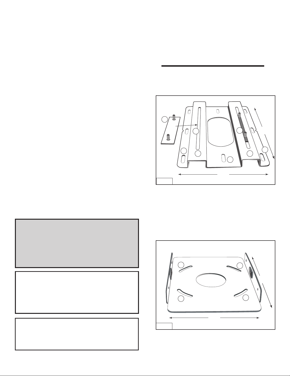
Step 1
Base Plate Connectors #1 and Projector Mount Ceiling
Plate 1 with
Figure 1
ceiling mounting holes #2.
1
4
2
3 3
Ceiling Wire
Access
4
2
8 5/8"
Plate 1
Base Plate Connectors #1
Projector Mount Ceiling Plate 1
Insert Base Plate connectors #1 into the lateral positioning slots
#
3 as shown in #4 from the underside of Plate 1. The lateral positioning
slots will give you 2 1/4" inches of lateral adjustment for projector
alignment.
14"
2
Warning
The ceiling should be capable of supporting a weight
of at least five (5) times the projector(s) weight.
If it cannot, the ceiling must be reinforced. Proper
installation procedure by qualified personnel as outlined
in the installation instructions must be adhered to.
Failure to do so could result in serious personal injury.
Hardware List
1. Four (4) 3/8 (inch) nuts
2. Fourteen (14) 3/8 (inch) flat washers
3. Four (4) 8 (mm) screws
4. Twelve (12) 1/4” screws
5. Two (2) 1” rubber washers
6. Two (2) 1” flat washers
Adjustment Ranges and Load Allowances
Horizontal Tilt (yaw) +/- 10 degrees
Vertical Tilt (tilt) +/- 20 degrees
Rotation +/- 15 degrees
Lateral Shift +/- 2
Maximum Load Allowance 32 Lbs.
7. One (1) Ceiling Mount #1
8. Two (2) Base Plate Connectors
9. One (1) Horizontal Tilt Plate #2
10. One (1) Horizontal Tilt Plate #3
11. One (1) Projector Plate #4
1/4
inches
Step 2
Horizontal Adjustment Plate 2 (Base Plate Connector
Holes #3).
Figure 2
3
Wire
Access
3
7 5/8"
Plate 2
Base plate connector holes #3 provide 15 degrees of horizontal
rotation adjustment.
Attach horizontal adjustment Plate 2 to projector mount ceiling
Plate 1 using the four (4) 3/8" (inch) nuts and washers provided.
3
10 5/8"
3
Page 4

MOUNT MT8600 PROJECTOR MOUNT INSTALLATION INSTRUCTIONS continued
Step 2 B
Horizontal Adjustment Plate 2 (Figure 2) attached to
Projector Mount Ceiling Plate 1.
Step 3 B
Horizontal Tilting Plate 3 Attached to Plates 1 and 2.
Figure 3
Wire
Access
Plates 1 & 2
Install the combined plates (above) securely to the ceiling
structure in accordance with local commercial building
standards.
Use suitable hardware in adequate quantity and size depending
on the installation requirements. (Please note that Projector
VP8600 weighs 31.1 lbs. (14.1 kgs).
Step 3
Horizontal Tilting Plate 3
Figure 5
Tilting Capability
Plate 3
The newly combined Plate 3 provides 10
Tilting Capability
0
degrees of
horizontal tilt. When positioned, tighten with screws
provided.
Step 4
Projector Mounting Plate 4
Figure 4
2
2
1
2
2 2
1
Holes for 1/4” screws with steel washer
2
Holes for 1/4” screws
Plate 3
2
Wire
Access
Indicates Forward
Positioning of Mount
2
2
2
1
2
Attach Horizontal Tilting Plate 3 to the previously combined
plates (already installed on ceiling) using the 1/4in.
provided, as indicated in Figure
screws with
(indicated
metal washers into the welded metal studs
#1).
4. Install two (2) 1/4in.
screws
Figure 6
mounting holes
Plate 4
Invert the projector and place it on a soft and flat
surface. Align the four (4) flat washers provided
with the four (4) 1/4in. mounting holes on the
projector and secure with four (4) 1/4in. screws
provided.
continued over
Page 5

MOUNT MT8600 PROJECTOR MOUNT INSTALLATION INSTRUCTIONS continued
Step 4 B
Projector Mounting Plate 4 (continued)
Projector Mounting Plate 4 connected to Mounting Plate 3
Figure 7
Plate 4
20
0
Tilt
CEILING
Mount Side
Projector Side
20
0
Tilt
Work in a group of 2 or more to carry the projector and follow
manufacturer's guidelines for relocating as stated in the VP8600
owner's manual.
Lift and slide the projector onto the 1/4in. screws previously
installed in the metal studs of the plate on the ceiling (see arrow
in Figure 7). Tighten the 1/4in. screws on both sides of the
mount and install four (4) 1/4in. screws and washers into the
side of the projector Mounting Plate 4.
Figure 8
Moun ts F ully Ass embl ed
Ceiling Side
Projector Side
Sequence of Assembly of Projector Mounting Plates
Plate 1
Step 2
Plate 2
Step 3
Plate 3
Step 4
Plate 4
Page 6

Assembly Drawing
10.22" (259.7)
7.33" (186.3)
4.06" (103.0)
3.64" (92.5)
14" (355.6)
17.13" (435.0)
6.34" (161.00) 8.43" (214.00)
8.6" (218.4)
Rotation
+/- 15 degree
Lateral Shift
+/- 2.25" (57.2)
Yaw
+/- 10 degree
Tilt
+/- 20degree
Unit: inch (mm)
Page 7

Ceiling Plate Templates
14.0" (355.6)
0.87" (22.0)
1.3" (33.0)
CEILING SIDE
8.6" (218.4)
3.8" (96.5) 3.8" (96.5)
5.5" (139.5) 5.5" (139.5)
0.3" (7.7)
2.75" (69.9)
7.25" (184.2)
1100 Maplewood Drive
Itasca, IL 60143
Phone: 630 741-0300 Fax: 630 741-0301
You can find your nearest Marantz authorized dealer
on our website at: www.marantz.com
Unit: inch (mm)
Printed in Canada
2005
 Loading...