

Page 1
Service
74 MR2020 /2G (Layla)
MR2020 F,K,KK,U
Manual
SECTION PAGE
MR2021 (CD/Tuner Amplifier)
1 TECHNICAL SPECIFICATIONS ............................................................................................................. 1-1
2-1 HOW TO DISASSEMBLE ....................................................................................................................... 2-1
2-2 REPAIR INTRODUCTION ...................................................................................................................... 2-6
2-3 EXPLANATION OF CIRCUITS ............................................................................................................... 2-6
3 SERVICE MODE ..................................................................................................................................... 3-1
4-1 BLOCK DIAGRAM .................................................................................................................................. 4-1
4-2 AM STEREO ADJ.(F ONLY) ................................................................................................................... 4-1
4-3 MICROPROCESSOR DATA ................................................................................................................... 4-1
5 WIRING DIAGRAM ................................................................................................................................. 5-1
6 SCHEMATIC DIAGRAM AND PARTS LOCATION.................................................................................6-1
7B TUNER BOARD ECO5 .........................................................................................................................7B-1
7D TUNER 95 BOARD .............................................................................................................................. 7D-1
8 CD NAMI 8 BOARD................................................................................................................................. 8-1
9 EXPLODED VIEW AND PARTS LIST..................................................................................................... 9-1
10 ELECTRICAL PARTS LIST ................................................................................................................... 10-1
CD/Tuner System
TABLE OF CONTENTS
CAUTION
The System MR2020 (Layla) combines MR2021 (CD/Tuner Amplifier) with LS2021 (Speaker System).
Printed in Japan
LS2021 ( Speaker System )
1 EXPLODED VIEW AND PARTS LIST.................................................................................................... 1-1
Please use this service manual with referring to the user guide ( D.F.U. ) without fail.
R
system MR2020 / Layla
4822 725 51183
First Issue 1999.01
298J855010 MIT
Page 2
MARANTZ DESIGN AND SERVICE
Using superior design and selected high grade components, MARANTZ company has created the ultimate in stereo sound.
Only original MARANTZ parts can insure that your MARANTZ product will continue to perform to the specifications for which
it is famous.
Parts for your
MARANTZ equipment are generally available to our National Marantz Subsidiary or Agent.
ORDERING PARTS :
Parts can be ordered either by mail or by Fax.. In both cases, the correct part number has to be specified.
The following information must be supplied to eliminate delays in processing your order :
1. Complete address
2. Complete part numbers and quantities required
3. Description of parts
4. Model number for which part is required
5. Way of shipment
6. Signature : any order form or Fax. must be signed, otherwise such part order will be considered as null and void.
USA CANADA EUROPE / TRADING
MARANTZ AMERICA, INC.
440 MEDINAH ROAD
ROSELLE, ILLINOIS 60172
USA
PHONE : 630 - 307 - 3100
FAX : 630 - 307 - 2687
USA CANADA
SUPERSCOPE TECHNOLOGIES, INC.
MARANTZ PROFESSIONAL PRODUCTS
2640 WHITE OAK CIRCLE, SUITE A
AURORA, ILLINOIS 60504 USA
PHONE : 630 - 820 - 4800
FAX : 630 - 820 - 8103
LENBROOK INDUSTRIES LIMITED
633 GRANITE COURT,
PICKERING, ONTARIO L1W 3K1
CANADA
PHONE : 905 - 831 - 6333
FAX : 905 - 831 - 6936
TC ELECTRONICS CANADA LTD.
540 FIRING AVE.
BAIE D’URFÉ, QUEBEC H9X 3T2
CANADA
PHONE : 514 - 457 - 4044
FAX : 514 - 457 - 5524
MARANTZ EUROPE B. V.
P.O.BOX 80002
BUILDING SFF2
5600 JB EINDHOVEN
THE NETHERLANDS
PHONE : +31 - 40 - 2732241
FAX : +31 - 40 - 2735578
KOREA
MK ENTERPRISES LTD.
2F SHINHAN BLDG., 247-17 SEOKYO-DONG
MAPO-KU, SEOUL
KOREA
PHONE : +82 - 2 - 323 - 2155
FAX : +31 - 2 - 323 - 2154
BRAZIL
MARANTZ BRAZIL
CAIXA POSTAL 21462
CEP 04698-970
SAO PAULO, SP, BRAZIL
PHONE : 0800 - 123123
FAX : +55 11 534. 8988
(Discagem Direta Gratuita)
AUSTRALIA / NEW ZEALAND
SCAN AUDIO PTY. LTD.
52 CROWN STREET, RICHMOND 3121
VICTORIA
AUSTRALIA
PHONE : +61 - 3 - 9429 - 2199
FAX : +61 - 3 - 9429 - 9309
JAPAN
Technical
MARANTZ JAPAN, INC.
35- I , 7- CHOME, SAGAMIONO
SAGAMIHARA - SHI, KANAGAWA
JAPAN 228-8505
PHONE : +81 42 748 1013
FAX : +81 42 741 9190
THAILAND
MRZ STANDARD CO., LTD.
746 - 754 MAHACHAI RD.,
WANGBURAPAPIROM, PHRANAKORN,
BANGKOK, 10200 THAILAND
PHONE : +66 - 2 - 222 - 9181
FAX : +66 - 2 - 224 - 6795
TAIWAN
PAl- YUING CO., LTD .
6 TH FL NO, 148 SUNG KIANG ROAD,
TAIPEI, 10429, TAIWAN R.O.C.
PHONE : +886 (2) 5221304
FAX : +886 (2) 5630415
MALAYSIA
WO KEE HONG ELECTRONICS SDN. BHD.
NO. 102 JALAN SS 21/35, DAMANSARA
UTAMA, 47400 PETALING JAYA
SELANGOR DARUL EHSAN,
MALAYSIA
PHONE : +60 3 - 7184666
FAX : +60 3 - 7173828
SINGAPORE
FORWARD MARKETING (S) PTE. LTD.
23, LORONG 8, TOA PAYOH,
SINGAPORE 319257.
PHONE : +65 2583640
FAX : +65 3564047
SHOCK, FIRE HAZARD SERVICE TEST :
CAUTION : After servicing this appliance and prior to returning to customer, measure the resistance between either primary AC
cord connector pins ( with unit NOT connected to AC mains and its Power switch ON ), and the f ace or Front Panel of product and
controls and chassis bottom.
Any resistance measurement less than 1 Megohms should cause unit to be repaired or corrected before AC power is applied, and
verified before it is return to the user/customer.
Ref. UL Standard N0. 1492(DR700) and No. 813(CDR630).
In case of difficulties, do not hesitate to contact the Technical
Department at above mentioned address.
98110MIT
Page 3

1-1
1. TECHNICAL SPECIFICATIONS
FM T uner
Frequency range............................................................................................................................................ 87.5 ~ 108.0 MHz
F only .................................................................................................................................... 76.0~ 90.0 MHz
Sensitivity ........................................................................................................................................................ 21.2 dBf / 3.2 µV
S/N (Mono/Stereo)..................................................................................................................................................... 75 / 43 dB
F only .......................................................................................................................................... 70 / 50 dB
THD (Mono/Stereo) ...................................................................................................................................................1.5 / 1.5 %
MW T uner
Frequency range............................................................................................................................................... 531 ~ 1602 kHz
U only ................................................................................................................................... 530 ~ 1700 kHz
Sensitivity ................................................................................................................................................................. 500 µV / m
/02, F only ............................................................................................................................................... 400 µV / m
S/N.................................................................................................................................................................................... 50 dB
L W T uner
Frequency range................................................................................................................................................. 153 ~ 279 kHz
Sensitivity ............................................................................................................................................................... 1800 µV / m
Amplifier
Music power................................................................................................................................................... 25 W + 25 W (4Ω)
Input sensitivity (AUX) .......................................................................................................................................310 mV / 47 kΩ
U only ............................................................................................................................ 250 mV / 47 kΩ
S/N (AUX) ......................................................................................................................................................................... 85 dB
CD Player
Channels ................................................................................................................................................................. 2 channels
Frequency response ...............................................................................................................................20 ~ 20,000 Hz ± 3 dB
S/N....................................................................................................................................................................82 dB (1000 Hz)
THD ................................................................................................................................................................0.04 % (1000 Hz)
Output level...................................................................................................................................................................2 V RMS
General
Power supply
/02 version.................................................................................................................................................. AC 230 V, 50 Hz
F version .........................................................................................................................................AC 100 V, 50Hz / 60 Hz
K version ............................................................................................................................. AC 110V / 220 V, 50Hz / 60 Hz
KK version.................................................................................................................................................. AC 220 V, 60 Hz
U version.................................................................................................................................................... AC 120 V, 60 Hz
Power consumption ............................................................................................................................................................25 W
Power failure backup time...............................................................................................................................APPROX. 15 min.
Dimensions ................................................................................................................................ 450(W) x 104(H) x 308(D) mm
Weight............................................................................................................................................................................... 5.8 kg
Table top Speaker LS2021
Speaker
Mid-bass ............................................................................................................................................................................4”
Dome tweeter..................................................................................................................................................................3/4”
Input power
Rated ................................................................................................................................................................... 25 W (6Ω)
Max. ..................................................................................................................................................................... 40 W (6Ω)
Frequency response ...............................................................................................................................80 ~ 20,000 Hz ± 6 dB
Dimensions .....................................................................................................................
Weight............................................................................................................................................................................... 1.5 kg
........... 190(W) x 200(H) x 100(D) mm
Design and specifications are subject to change without notice.
Page 4
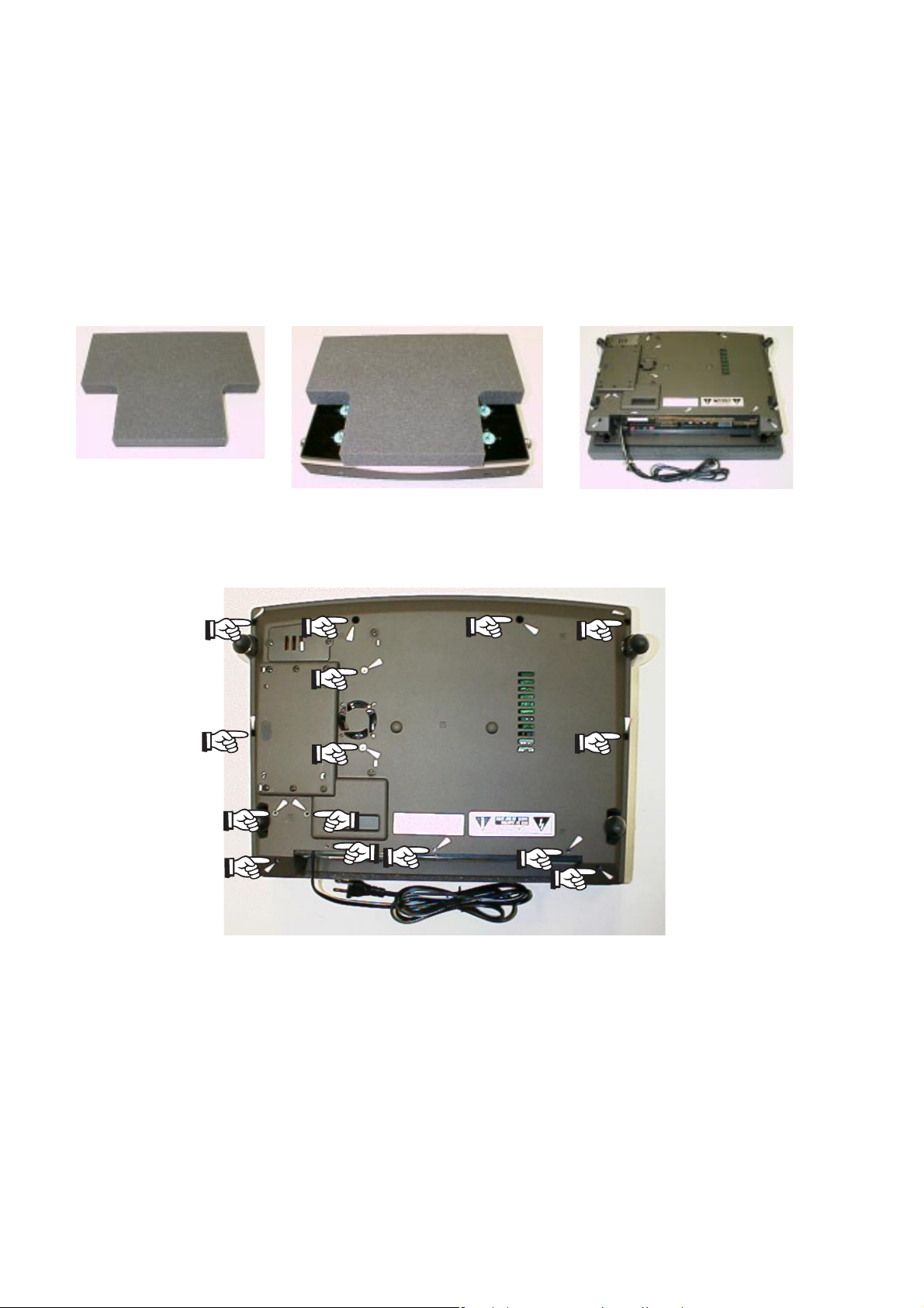
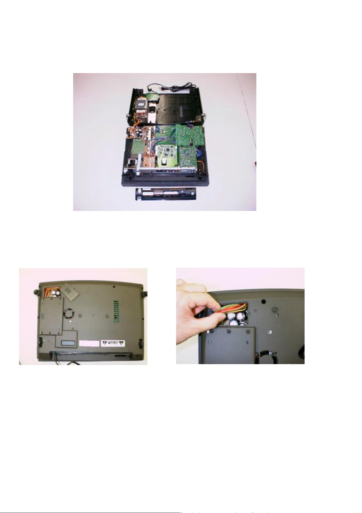
2-1. HOW TO DISASSEMBLE MR2020
1. Take the bottom case (001G) apart
(1) Tur n MR2020 upside down by the jig (Refer to fig.1-3).
Take care that the top cover will not damaged, especially
the 4 levers. If you don't have the jig, you prepare to put
some magazine or telephone guide under the MR2020
(The height is over 3cm books).
2-1
Fig.1 A jig for MR2020
(2) Remove 15 screws as shown in fig.4.
Fig.2 The jig on MR2020 Fig.3 Turning over the MR2020
Fig.4 Position of 15 screws
Page 5
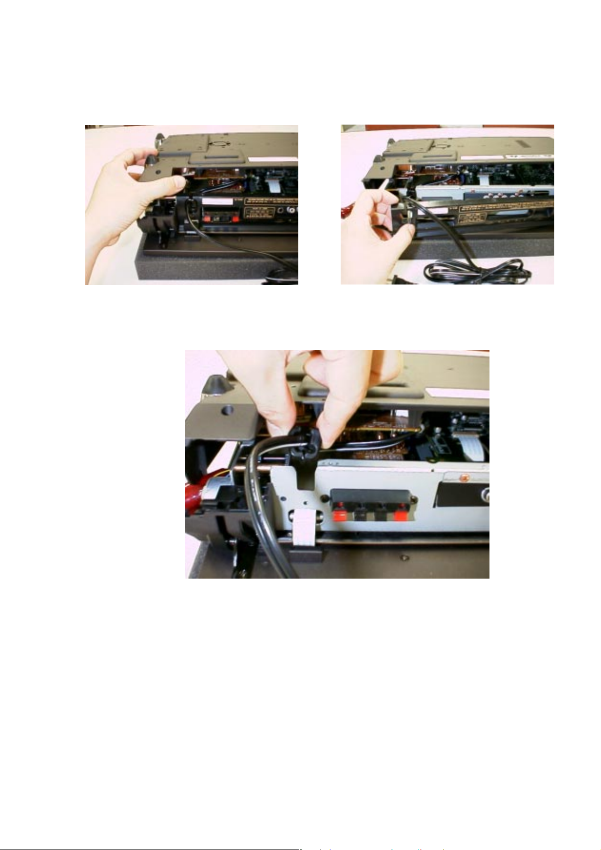
(3) While lifting the bottom case, remove the rear panel as
shown in fig.5-6.
2-2
Fig.5 Lifting the bottom case
(4) Remove the mains code bush as shown in fig.7.
Fig.6 Removing the rear panel
Fig.7 Removing the mains code bush
Page 6
(5) Lift up the bottom case, remov e the put the one with turning
to front side (Refer to fig.8).
2-3
Fig.8 Taking the bottom case apart
Remark for reassemble
When you fit the bottom case, remove the lid of the bottom
case (Refer to fig.9) and confirm the arrangement of lead
lines for transformer.(Refer to fig.10).
Fig.9 Removing the lid of the bottom case
Fig.10 Arrangement of lead lines
Page 7
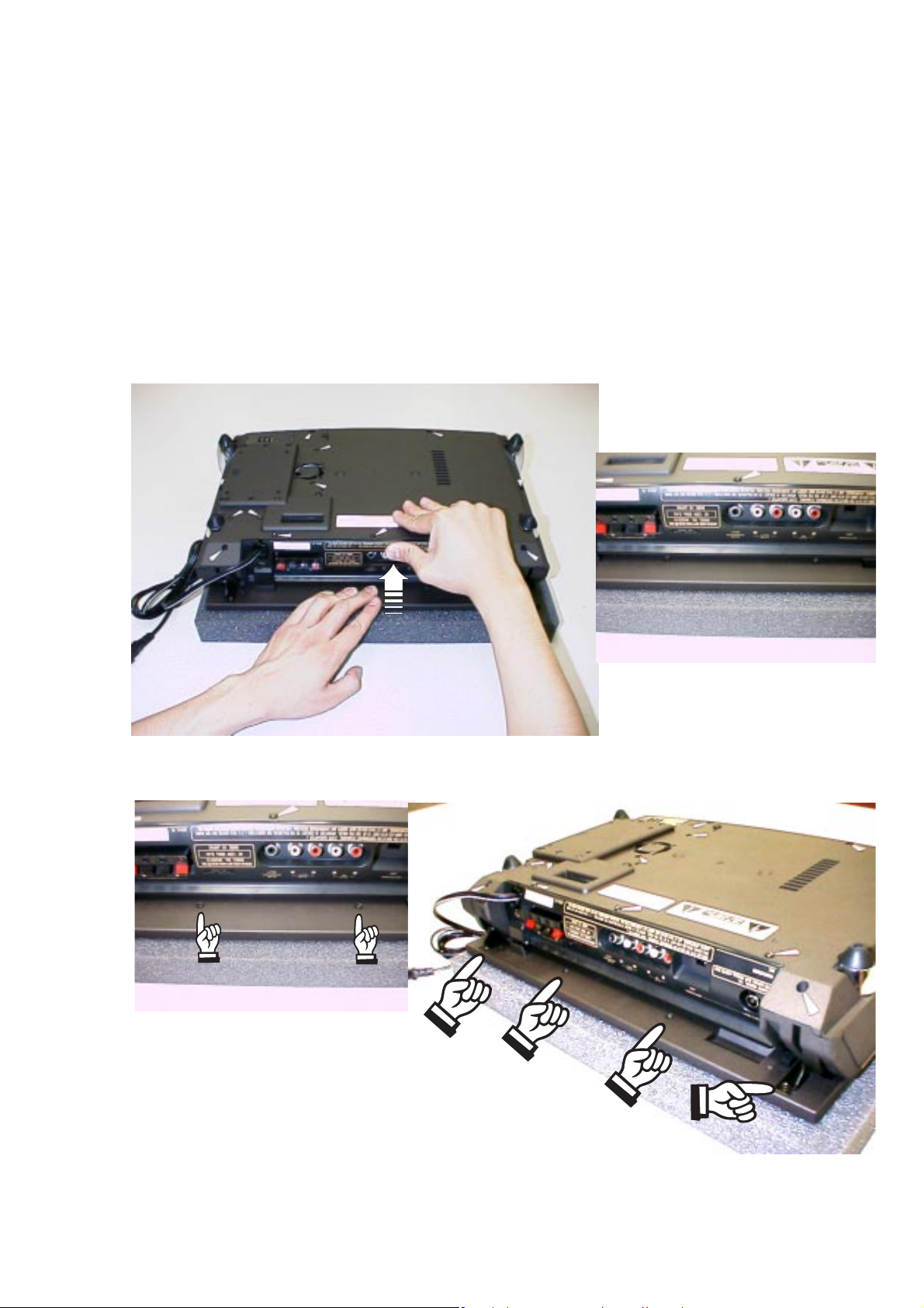
2. Take the top panel (001D) apart
(1) Turn MR2020 upside down by the jig. (Refer to fig.1-3)
Take care that the top cover will not damaged, especially
the 4 levers. If you don't have the jig, you prepare to put
some magazine or telephone guide under the MR2020.
(The height is over 3cm books)
(2) Push the rear panel while keeping hold the top cover (see
fig.11 below). The top cover will move 5mm. (fig.12-13)
Now, 4 screws on the top cover will become accessible.
(fig.14) Take out these screws. (M3 type screw)
2-4
Fig.11 Pushing the rear panel
Fig.13 Pushed the rear panel
Fig.12 Before pushing the rear panel
Fig.14 Positions of 4 screws
Page 8

(3) Turn the MR2020 to its normal operating position.
(4) Open the top cover of MR2020 by hand.
(5) Take out the 2 screws (M2 type screw) on the top (see
fig.15).
2-5
Fig.15 Positions of 2 screws on the top
(6) The upper par t and lower part of the top cover are
connected to each other with adhesive tape. Separate
these parts by pushing the transparent upper part in the
middle (on CD shaped part) from the lower part, while
holding the lower part.
(7) The upper part and lower part of the top co ver were
separated (See fig.16-17).
Fig.16 The upper part of top cover (the reverse side)
Fig.17 The lower part of top cover and the others
Page 9

2-2. REP AIR INTRODUCTION
PREPARATION FOR CD BLOCK
1. Set a disc for repair into product.
2. Tur n the product upside down on the jig (Parts
No.*MR2021JIG). Take care that the top cover will not
damaged, especially the 4 lever s. (Refer to "How to
disassemble MD2020")
3. For the top panel will not open while repairing, remove
the connecting wires of panel motor from the connector
(J812).
4. Repair and operate it on the upside down position of
the product.
PREPARATION FOR MAIN AMPLIFIER PCB (P704)
1. Main amplifier is BTL output.
2. For removing the main amplifier PCB (P704) from the
product, remove the wire (W802) from the terminal
(WU02) of microprocessor PCB (PU04). Connect
another wire with terminal (WU02) and GND as chassis
instead of the wire (W802).
REMARK
Remove the bottom case from the product, Do not output
signals of over 1W from both channels more than 10
minutes continuously.
2-6
2-3. EXPLANA TION OF CIRCUITS
FAN OPERATION
The voltage added to the diode (D852) is depended on
the resistance of the thermistor (R857) and resistors
(R855,R858). When the temperature of the heat sink
goes up, the resistance of the thermisor (R857)
decreases, and the voltage added to the diode (D852)
increases.
1. When the temperature of the heat sink is over 70
degrees Celsius, then D852 is on, through R852, Q851
is on, and the fan starts to revolve.
2. When the temperature of the heat sink is approx. 100
degrees Celsius or more, through R853, Q853 is on,
and the product is STAND-BY status. But, if the fan
revolve normally, the temperature of the heat sink will
not be over 100 degrees Celsius and not be STANDBY status. Therefore, the procedure of the o ver heat
protection circuit check is as follows;
(1) Connect the test point (J814) with a resistor of 680
ohm.
(2) If the product is STAND-BY status, this circuit is normal.
(3) Remove the resistor of 680 ohm from the test point
(J814).
FAN OPERATION CHECK
Keep outputting 2.5W from both channels of the product.
Page 10

When the bottom case is closing. If the fan revolving starts
within 10 minutes, the function is correct working.
Otherwise keep outputting 1W from both channels of the
product when the bottom case is opening. If the f an revolving
starts within 5 minutes, the function is correct working.
REMARK
Do not output over 1W when the bottom case is open.
VCC CONTROL
The regulation of primary voltage is not so higher
intentionally for decreasing the no-load loss. Therefore, this
circuit is used for the product to keep the voltage tolerance
of the power IC. This circuit do not work when the output is
from 0 to approx. 1Vrms. Then VCC is supplied from D709
only. When the output is more than 1Vrms, through D701D704, R722, D706, and Q703 is on, current is supplied
from Q702. When the output is over approx. 3Vrms, D709
is off, and VCC is supplied from Q702 only.
SPEAKER PROTECTION
1. When either terminal of BTL outputs connect with GND
(chassis) by mistake, the speaker protection circuit will
work as follows. through R707-R710, Q704 or Q705 is
on, and Q706 is on. Then #5Pin for Q701 is 0V, power IC
(Q701) will be in power off. Therefore, the product will be
STAND-BY status.
2. When the VCC CONTROL circuit is working correctly,
maximum current of R825 is 1A, and voltage between
R825 load is maximum 0.33V. When both terminals of BTL
outputs are shorted on outputting over 0.25W, R825 is
supplied over 2A, Q807 and Q803 is on, and the product
will be STAND-BY status.
2-7
CD 5V ON/OFF CONTROL
The voltage for CD (CD 5V) is supplied from QX04 when
the following conditions are satisfied fully. (for noise and
laser protection)
1. Setting a disc on the product, and QU08 is on.
2. Closing top panel, and #78Pin for QU10 is 0V.
3. The product is in CD mode.
MUTE CONTROL
Mute signals output from microprocessor (QU10) are
"MUTE (Pin No.37)", "MUTE2 (Pin No .7)", and "DSC MUTE
(Pin No.5)".
Fig.1 is workable output terminals by each mute signals,
Fig.2 is the status of each mute.
Q701(SPK)
MUTE YES YES YES NO NO
MUTE2 NO NO
DSC MUTE NO NO NO NO YES
QN01-QN04
(PHONE)
Fig.1
QX05,QX06
(SUB WOOFER)
QX07,QX08
(LINE OUT)
YESNO
QE01
NO
Page 11

2-8
Fig.2
POWER
ON/OFF
MUTE YES YES YES YES YES
MUTE2 YES YES NO YES NO
DSC MUTE NO YES NO NO NO
TOP PANEL OPEN SENSOR
1. The pulse (T=84msec, Duty 50%) is always added to LED
(QU15), from #30Pin of QU10, through RF28 and QU22.
2. Cover the sensor with your fingers, the collector voltage
of QU01 goes up over 0.7VP-P. and through RU71 and
QU09, the pulse of 5VP-P inputs to #29Pin of QU10. Then
the top panel will open.
3. Not needing to cover the sensor with your fingers, QU01
receives the light of LED reflected by lens oneself.
Therefore, the collector of QU01 adds the reverse pulse
through RF29, QU26 and RF32, for reduced incorrect
working. So, the voltage of residual pulse for the collector
of QU01 is suppressed to 0.1VP-P.
REMARK
When the sensor receives sunlight or a strong light as
incandescent, top panel might open.
CD MODE STOP OR
TRACK JUMP
MUTE BUTTON
ON
MODE
CHANGE
VOLUME
MINIMUM
POPS NOISE KILLER
RX72, CX70 and QX70 are the circuit to delay power supply
for approx. 2 seconds. Therefore, this circuit prevents pops
noise generation when power switch is on or off.
SUB WOOFER
Sub woofer output is composed a low pass filter of cut-off
frequency 150Hz octave 12dB. It is output 2V for AUX L,R
input 60Hz, 200mV (volume is maximum).
REMARK
Sub woofer output level is depended on volume control.
Page 12
3 SERVICE MODE
1. How to set the service mode
(1) While holding the CLOCK and CLEAR buttons together,
put the mains plug to mains outlet.
(2) FL check mode will start.
(3) While in FL check mode, each time the FUNCTION button
pressed (within 2 seconds), the mode changes in the
following order.
TR FREQ (Tracking point frequency memory mode) ➛
CD TEST (CD test mode) ➛ FL CHK (FL check mode) ➛
TR FREQ (Tracking point frequency memory mode)
2. FL CHECK MODE
FL check mode will continue until change other mode.
3. TRACKING POINT FREQUENCY MEMORY MODE
This mode is not available for repair(This is for check in
factory.). If you set in this mode, some frequencies will
register in each preset memory.
REMARK
User programmed frequencies will be deleted.
While in Tracking point frequency memory mode, press the
MEMO button. Press the CLEAR and the DISPLAY buttons
together. The display shows “CLEAR” 2 seconds. Then all
memories will be clear.
3-1
4. CD TEST MODE
(1) Press the “+ ” button, then the sledge move to the outside.
Press the “-” button then the sledge move to the inside.
Press the CLEAR button while the sledge is moving, then
the sledge stop.
(2) Press the MEMO button, then the laser pick up unit is
giving out the beam. Press the MEMO button again then
the laser pick up unit stop beam out. All operations are
available without the Disc.
(3) While in CD test mode, CD play is available in opening
the top panel.
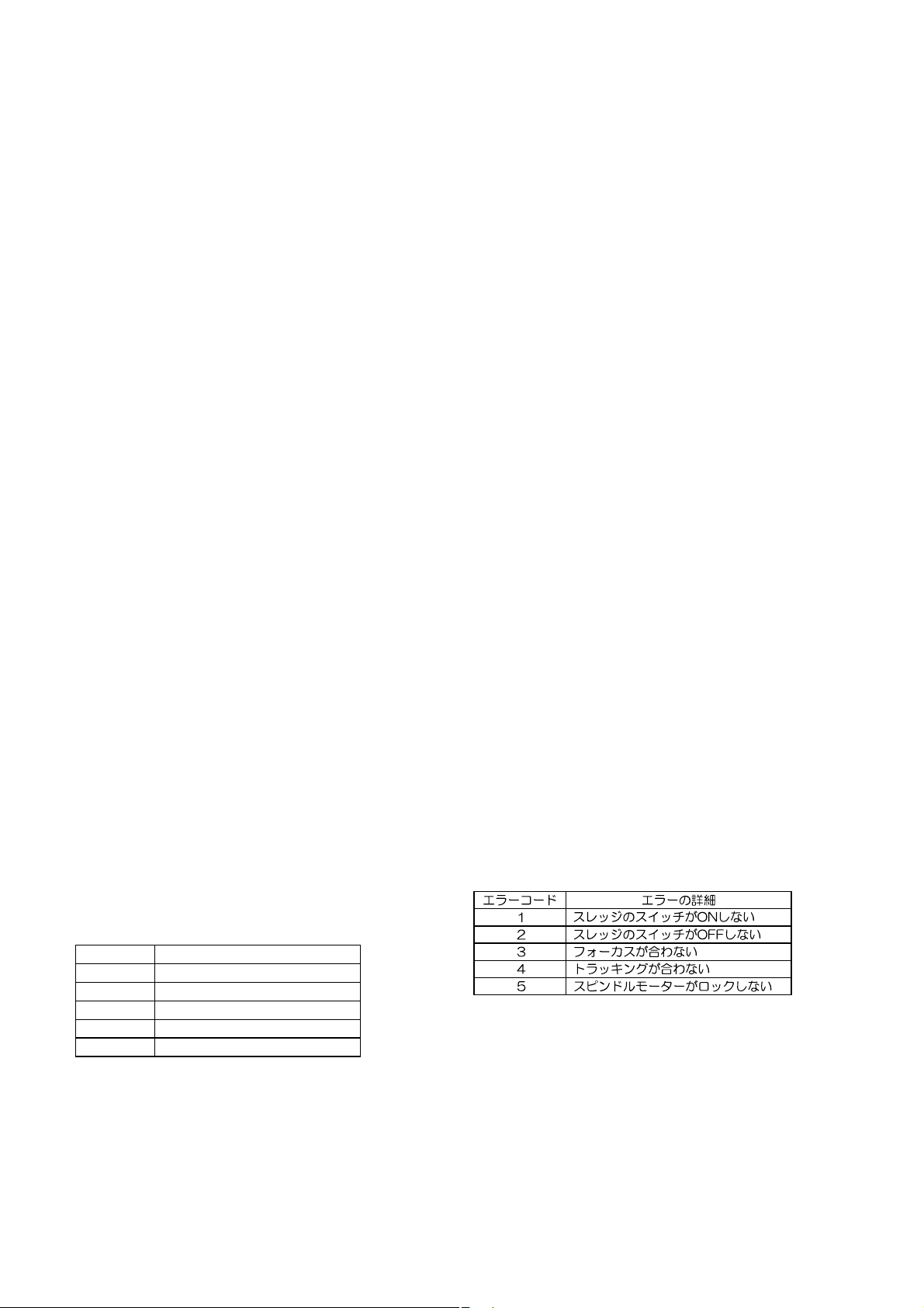
(4) If any ERROR is happened, the displa y shows “CD ERRX”.
(X is a ERROR code.) The ERROR message will not be
clear until pressing STOP or POWER buttons.
Error Code Description
1 The sledge switch not turn on.
2 The sledge switch not turn off.
3 The laser pick up unit not focus.
4 The tracking is not fixed.
5 The spindle motor not locked.
5. How to stop the service mode
Press the POWER button. Then product will be in POWER
OFF (STAND-BY).
REMARK
The microprocessor will not be clear by this operation.
(Refer to "3. TRACKING POINT FREQUENCY MEMORY
MODE")
Page 13

4-1 4-1
4-1 BLOCK DIAGRAM
CD UNIT CD94V5B1
SPNDLE
MOTOR
SLED
MOTOR
D SC
SENSOR(CD)
PCK UP
FOCUS
TRACK
TDA7073AT
TDA7073AT
SUPPLY
TDA1300T
HF AMP
SERVO
DRIVER
SERVO
DRVER
CD BOARD NAMI 8
DECODER/
U-COM
SAA7372
PQ30RV2 PQ05RF2
+10V
2SA1307
+21V
U COM
PQ12RF2
+20V
U COM
+8V +5V
DAC
U COM
AM STEREO
F ONLY
7808
ANT
TUNER 95
ECO 5
RDS
/02 ONLY
ANALOG
+5V(CD)
+5V U COM)
+9 3V(POWER AMP)
+8V(CD)
+12V(PANEL MOTOR)
26V(FL)
F1(FL)
F2(FL)
4-3 MICROPROCESSOR DATA
AUX
L NE
IN
BUFFER
NJM4558
+5V
MAIN U COM
A/D INPUT
PANEL
DR VE
C
SUB
OUT
W F
DRIVER
TEMP
DETECT
POWER
AN7125
H P AMP
NJM4556
FL
AMP
S P
H P(SW)
DISPLAY
R C
PANEL
PHOTO
SENSOR
FL
RC5
M
FAN
MOTOR
BUFFER
NJM4558
I2C
PANEL
ON TOP
OPN/CLS
KEY
PRE AMP
TE6321
BOTTOM
E Q
KEY
Pin No Pin Name S gnal Name I/O Active Slow Function
1 P10 (INT0) POW DWN INT L POWER DOWN
2 P11 (INT1) STANDBY OUT L L POWER STANDBY
3 P12 (INT2) SDA N/OUT I C SDA(for RDS DSC)
4 P13 (DVO) SCL OUT H L I C SCL(for RDS DSC)
5 P14 DSC MUTE OUT L L DSC MUTE
6 P15 CD STANDBY OUT L L CD STANDBY
7 P16 MUTE2 OUT L L L NE MUTE
8P17 * N NC
9 TEST N GND
10 P21 (XTIN) 32 768kHz IN SUB X TAL
11 P22 (XTOUT) 32 768kHz OUT SUB X TAL
12 RESET RESET N L RESET
13 XIN 8 0MHz IN X TAL
14 XOUT 8 0MHz OUT X TAL
15 VSS GND GND
16 P20 (INT5) HOLD IN L HOLD N
17 P30 (INT3) RCIN INT RC 5 BUS IN
18 P31 RCOUT OUT L L RC 5 BUS OUT
19 P32 (SCK) UNE CLK OUT H L TUNER CLK
20 P33 (SI) TUNE WE OUT L TUNER WRITE ENABLE
21 P34 (SO) UNE SDA IN/OUT H L TUNER SDA
22 P35 (HSCK) TUNER ST M ON IN H L TUNER STEREO/MONO
23 P36 CD7 RESET OU T L L CD7 RESET
24 P37 (HSO) DISC IN IN H DISC IN SENSOR
25 P00 SILD OUT L L CD7 CONTROL
26 P01 RAB OUT H L CD7 CONTROL
27 P02 SCL OUT H L CD7 CONTROL
28 P03 SDA IN/OUT H L CD7 CONTROL
29 P04 P SEN IN N H PANEL SENSOR IN
30 P05 P SEN OUT OUT H L PANEL SENSOR OUT
31 P06 P MOTOR P OUT H L PANEL MOTOR +
32 P07 P MOTOR N OUT H L PANRL MOTOR
33 VDD +5V +5VS VDD
34 P60 (G15) * IN N C
35 P61 (G14) * IN N C
36 P62 (G13) AMPON OUT H L AMP POWER ON
37 P63 (G12) MUTE OUT H L MUTE
38 P64 (G11) RDS ON OUT H L RDS POWER
39 P65 (G10) 11G OUT H DIGIT OUT
40 P66 (G9) 10G OUT H DIGIT OUT
Pin No Pin Name Signal Name I/O Active Slow Function
41 P67 (G8) 9G OUT H DIGIT OUT
42 P70 (G7) 8G OUT H DIGIT OUT
43 P71 (G6) 7G OUT H DIGIT OUT
44 P72 (G5) 6G OUT H DIGIT OUT
45 P73 (G4) 5G OUT H DIGIT OUT
46 P74 (G3) 4G OUT H DIGIT OUT
47 P75 (G2) 3G OUT H DIGIT OUT
48 P76 (G1) 2G OUT H DIGIT OUT
49 P77 (G0) 1G OUT H DIGIT OUT
50 P80 (S0) P16 OUT H SEGMENT OUT
51 P81 (S1) P15 OUT H SEGMENT OUT
52 P82 (S2) P14 OUT H SEGMENT OUT
53 P83 (S3) P13 OUT H SEGMENT OUT
54 P84 (S4) P12 OUT H SEGMENT OUT
55 P85 (S5) P11 OUT H SEGMENT OUT
56 P86 (S6) P10 OUT H SEGMENT OUT
57 P87 (S7) P9 OUT H SEGMENT OUT
58 P90 (S8) P8 OUT H SEGMENT OUT
59 P91 (S9) P7 OUT H SEGMENT OUT
60 P92 (S10) P6 OUT H SEGMENT OUT
61 P93 (S11) P5 OUT H SEGMENT OUT
62 P94 (S12) P4 OUT H SEGMENT OUT
63 P95 (S13) P3 OUT H SEGMENT OUT
64 P96 (S14) P2 OUT H SEGMENT OUT
65 P97 (S15) P1 OUT H SEGMENT OUT
66 VKK B Power Supply for FL
67 P40 (KEY0) Key0 IN H Key0
68 P41 (KEY1) Key1 IN H Key1
69 P42 (KEY2) Key2 IN H Key2
70 P43 (KEY3) Key3 IN H Key3
71 P44 (KEY4) Key4 IN H Key4
72 P45 (KEY5) Key5 IN H Key5
73 P46 (KEY6) Key6 IN H Key6
74 P47 (KEY7) Key7 IN H Key7
75 P50 (A D) DAVN N L RDS DAVAN
76 P51 (A D) PSWN N L RDS PSWN
77 P52 (A D) P OPEN N L PANEL SW OPEN
78 P53 (A D) P CLOSE N L PANEL SW CLOSE
79 P54 VER SET0 IN 0 1 0 1
80 P55 VER SET1 IN 0 0 1 1
:F
:U
:K KK
: /2
Page 14

. WIRING DIAGRAM
5-1 5-1
NAMI 8
F ONLY
CD94V5B1
TUNER 95
or ECO 5
Page 15

6. SCHEMATIC DIAGRAM AND PARTS LOCATI O N
WU09
(FROM JU01)
6-1 6-1
PHONE
Page 16

6-2 6-2
/02
/02
002M
/02
SPEAKER
OUT
Page 17

6-3 6-3
PX04
QN03 QN01 QH01
QX04 QX01 QX02 QX05 QX06
QX70
QN04 QN02
QX07 QX03 QX08
QE04 QE03
P704
QE04 QE02
QX09
PX54
Q708 Q707 Q701
Q705 Q704 Q706 Q703
P804
Q702 Q801 Q805 Q806
Q852 Q851 Q803 Q807
QD01 Q853
PH04
Page 18

D BOARD
NAMI 8
6-4 6-4
/02
/02
PS64
TUNER BOARD
TUNER 95
or ECO5
/02
Page 19

6-5 6-5
PU04
QU12 QU13 QU14 QU15
QU04 QU03
QU08
QU22 QU26 QU09
QU28 QU27
QU25 QU24 QU23
QU10
PS54
QU21 QU16 QU17 1U28
QU06 QU07 QU05
QU18 QU19 QU20 QF51
PS04 PS14
Page 20

AM STEREO
[F] VERSION
6-6 6-6
TUNER
BOARD
ECO 5
From
1131
PA01 QA01 QA04 QA03 QA02
Page 21

7B-1
6
1
1
TUNER BOARD ECO5
BLOCK DIAGRAM
TUNER BOARD
ECO 5
systems
V
1101
Loop
(1102)
A
FM
FMOsc
V
Loop
AM-Osc
V
AM FRAME AERIAL
Loop
1103
AM-RF
C
V
Loop
B
1
V
Loop
V
A
Stab
B
V
Stab
7B-1
V
A V
B
Stab
35 9
Multi
plexer
F2
RADIO IC
TEA 5757T
AM
Det
IF1
AM IF
AGC
4140 36 193244 25
BV
FM
Mixer
FM
Osc
AM
Osc
AM
Mixer
723
Vcc2
Stab
107 MHz 107 MHz
Pre
scaler
22
V
StabAVStab
FM-RF
3393733
43
FM
frontend
5
6
2
AM
Frontend
8
Charge
pump
38
34
Vdd Vcc1
Discriminator
450kHz450kHz450kHz
B
Stab
107 MHz
FM
Det
AFC
AFC -
2
bu fer ampl
5
LF f lter
1018 11
AFC +
20
RDS
(MPX)
CONTROL
Refe ence
Oscilator
VCO
S ereo
Decoder
programmable
output ports
75kHz
r ght
stereo
enabe
Vcc1
Vdd
Vcc2
1124
Vcc
4
4
Version
MW LW
AM RF
AM Osc
right
4
le t
1
3
1126
112
stereo
4
c ock
da a
enabe
1
RDS
(MPX)
ECO5 sys 240698
15
14
eft
24
clock
27
data
28
29
31
P1
30
P0
TABLE OF CONTENTS
Blockdiagram ................................................................. 7B-1
Adjustmant table ........................................................... 7B-2
Component layout...........................................................7B-3
Circuit diagram................................................................7B-4
Parts list ......................................................................... 7B-5
Page 22

7B-2 7B-2
TUNER ADJUSTMENT TABLE ( ECO5 FM/MW- and FM/MW/LW - versions with AM-frame aerial )
Waverange Input frequency Input Tuned to Adjust Output Scope/Voltmeter
VARICAP ALIGNMENT
FM
87.5 - 108MHz
(65 81 74 87 5 108MHz)
MW
FM/AM version 10kHz grid
530 - 1700kHz
FM/MW version 9kHz grid
531 - 1602kHz
LW
153 - 279kHz
MW
FM/MW LW version 9kHz grid
531 - 1602kHz
FM IF
10.7MHz, 50mV
continuous wave
108MHz
87.5MHz
(65 81MHz)
1700kHz
530kHz
1602kHz
531kHz
279kHz
153kHz
1602kHz
531kHz
IC 7101
shor circuit
to b ock AFC
FM RF
FM
87.5 - 108MHz
(65 81 74 87 5 108MHz)
108MHz
87.5MHz
(65 81MHz)
A
mod=1kHz
Δf=±22.5kHz
108MHz 2155
87.5MHz
(65 81MHz)
VCO
FM
AM IF
98MHz, 1mV
continuous wave
98MHz
A
IC 7101
C
MW
AM AFC
MW
3)
AM RF
4)
MW
FM/MW/LW and FM/MW version
( 9kHz grid)
531 - 1602kHz
LW
MW
FM/AM version 10kHz grid
530 - 1700kHz
Use service test program By selecting the TUNER TEST test frequenc es will be stored as preset frequencies automatically
1)
If sens tivity of frequency counter is too low adjust to max channel separat on
(input s gnal stereo left 90% + 9% adjust output on right channel to min mum)
3)
For AM RF adjustments the or ginal frame antenna has to be used !
Repeat
450kHz
connect pin 6 of
IC 7101 (AM Osc.)
with short wire to
ground (pin 4)
1494kHz
558kHz
Δf=±15kHz
V
continuous wave
VRF = 10mV
RF
= 3mV
C
B
see
remark
IC 7101
2)
1494kHz
558kHz
198kHz
1500kHz
560kHz 5102
Δf = ±30kHz
V
RF
possible
as low as
1500kHz
560kHz
5130
check
5123
check
5123
check
5122
check
5123
check
21
5119FM
2141
5131
3142 152kHz ±1kHz
36
100nF
5111
220R
40
100nF
5112
220R
5114
8V ±0.2V
4.3V ±0.5V
(1 2V ±0 5V)
8V ±0.2V
1.1V ±0.4V
6.9V ±0.2V
1
1.1V ±0.4V
8V ±0.2V
1.1V ±0.4V
8V ±0.2V
1.1V ±0.4V
0 ± 3 mV DC
2F
4
MAX
3
4
f
o
symmetrc
0 ± 2 mV DC
2
2106
5102
5103198kHz
4
2106
2)
RC network serves for damp ng the IF filter while adjusting the other one
4)
MW has to be al gned before LW
f
o
symmetrc
ECO5 discr co l 090797
TUNER ADJUSTMENT TABLE
( ECO5 FM/MW- stereo versions with AM-frame aerial )
Waverange Input frequency Input Tuned to Adjust Output Scope/Voltmeter
VARICAP ALIGNMENT
FM
87.5 - 108MHz
FM Japan
76 - 90MHz plus
Ch1 95 75MHz Ch2 101 75MHz
Ch3 107 75MHz
MW
FM/AM version 10kHz grid
530 - 1700kHz
MW
FM/MW version 9kHz grid
531 - 1602kHz
FM IF
10.7MHz, 50mV
continuous wave
108MHz
87.5MHz
107,75MHz
76MHz
1700kHz
530kHz
1602kHz
531kHz
C 7101
shortcircuit
to block AFC
5130
check
5130
check
5123
check
5123
check
21
5119FM
2141
8V ±0.2V
4.3V ±0.5V
8V ±0.2V
2.4V ±0.5V
1
8V ±0.2V
1.1V ±0.4V
6.9V ±0.2V
1.1V ±0.4V
0 ± 3 mV DC
2F
FM RF
FM
87.5 - 108MHz
FM Japan
76 - 90MHz plus
Ch1 95 75MHz Ch2 101 75MHz
Ch3 107 75MHz
108MHz
87.5MHz
107.75MHz
76MHz
A
mod=1kHz
Δf=±22.5kHz
108MHz
87.5MHz
107.75MHz
76MHz
2155
5131
2155
5131
5
MAX
VCO
98MHz, 1mV
1)
FM
AM IF
max.
MW
AM AFC
MW
IF stereo module
MW
3)
max.
AM RF
MW
FM/MW version 9kHz grid
531 - 1602kHz
MW
FM/AM version 10kHz grid
530 - 1700kHz
Use serv ce test program By selecting the TUNER TEST test frequencies will be stored as preset frequencies automatica ly
1)
If sensit vity of frequency counter s too low adjust to max channel separat on
( nput signal stereo left 90% + 9% adjust output on right channel to minimum)
3)
For AM RF adjustments the original frame antenna has to be used !
(83MHz for Japan)
continuous wave
Δf=±15kHz
V
450kHz
connect pin 6 of
IC 7101 (AM Osc.)
with short wire to
ground (pin 4)
RF
cont nuous wave
VRF = 10mV
Δf=±15kHz
V
RF
1494kHz
558kHz
1500kHz
560kHz 5102
Δf = ±30kHz
V
RF
possible
A
C
= 3mV
C
100nF
50R
= 1mV
B
as low as
98MHz
(83MHz for Japan)
C 7101
36
100nF
220R
C 7101
40
100nF
see
220R
2)
remark
E
1494kHz
558kHz
1500kHz
560kHz
2)
RC network serves for damping the IF f lter while adjusting the other one
Repeat
3142 152kHz ±1kHz
3
5111
5
5112
5114
2
5240
4
2106
5102
4
2106
f
o
symmetrc
0 ± 2 mV DC
f
o
symmetrc
ECO5 AM stereo discr co l 090797
1)
max
max
max
Page 23

1101 A 1
1102 A 1
1103 C1
1104 B 1
1105 A 1
1119 C5
1120 A 5
1130 B 5
1131 B 5
2104 A 2
2105 A 1
1 2345
ECO 5 TUNER BOARD /
A
A
FM 75 OHM
1102
FM 300 OHM
B
1101
SW
D
1104
B
C
AM FRAME AERIAL
This assembly drawing shows a summary
of a l possible versions
For components used in a specific version
see schematic diagram respectively parts ist
1 2345
2106 C2
2107 C2
2110 C2
2115 C1
2123 A 2
2125 A 2
2128 C3
2129 C4
2130 A 4
2133 A 4
2135 B 5
SW
SW RF
FRAME
AM
1103
2137 C5
2138 A 5
2144 B 5
2148 B 4
2155 A 3
2162 A 2
3105 B 3
3110 A 2
3132 B 3
3142 A 4
3147 B 5
3149 C5
3152 A 5
3154 C5
3157 B 5
3158 A 5
3159 A 5
3160 A 5
3161 A 5
3170 C5
3171 C5
3172 C5
3173 A 5
5102 C2
5103 C2
5104 C2
5105 B 2
5106 B 2
5109 B 4
5110 B 4
5111 C3
5112 C4
5113 B 3
7B-3
5114 C4
5115 A 4
5116 A 4
5119 B 5
5120 B 4
5121 B 4
5122 B 3
5123 B 2
5124 B 2
5126 B 3
5127 B4
5130 A 3
5131 A 3
6101 A 2
6102 A 1
6103 A 1
6104 A 2
6106 B 3
6107 C5
6109 C2
6120 C4
7102 A 3
7104 C2
7105 C3
7107 B 3
7119 C4
9100 A 2
9101 B 3
9105 B 2
9111 C2
9113 B 2
9114 B 2
9115 B 3
9117 B 2
9118 B 4
9119 C4
9120 B 4
9121 A 2
9122 C3
9123 B 1
9124 C4
9125 A 3
9126 B 5
9128 A 2
9129 B 3
9130 C3
9131 A 5
9133 C3
9134 B 3
9136 A 5
9137 A 5
2101 C4
2102 C4
2103 C3
2108 A 4
2109 A 4
2111 A 2
2112 B 5
2113 A 4
2114 A 4
2116 B 3
2117 A 3
2118 B 4
2119 B 4
2120 B 4
2122 B 3
2124 A 5
2126 C2
2127 C2
2131 C2
2132 C1
2134 C1
2136 B 1
2139 B 2
2141 B 1
2142 B 1
2143 A 1
2145 C1
2146 C1
2147 C1
2149 B 2
2150 B 2
2151 C2
2152 C3
2153 C3
2154 C3
2156 C4
2157 B 4
2158 B 4
2159 C2
2160 C4
2161 A 3
2163 A 2
2164 B 1
2165 B 3
2166 B 2
2167 B 2
2168 B 1
3101 C3
3102 C3
3103 C3
3104 B 3
3106 C4
3108 A 4
3109 A 4
3111 A 3
3112 A 3
3113 A 2
3114 A 3
3115 A 3
3116 A 3
3117 B 4
3118 B 3
3119 A 3
3120 B 4
3121 A 3
3122 B 3
3123 A 3
3125 A 3
3126 B 3
3127 B 3
3128 B 3
3133 B 4
3134 B 4
3136 B 4
3137 B 4
3140 B 2
3141 C2
7B-3
3143 C2
3144 C2
3145 C2
3146 A 1
3148 A 1
3153 C2
3155 A 2
3156 A 1
3167 C2
3168 B 3
3169 B 2
3175 A 2
3176 C2
3177 A 1
3178 A 1
3179 A 1
3180 A 4
3181 C3
4101 A 4
4102 A 4
4103 C2
4104 A 2
4105 B 3
4106 B 4
4107 C4
4108 B 4
4109 A 3
4110 A 3
4111 C1
4120 C2
4150 B 2
4151 B 3
4152 B 3
4153 B 4
4154 C3
4155 A 4
4156 A 2
4157 B 3
4158 C2
4159 A 2
4160 A 1
4161 A1
4162 C1
4163 C1
6105 A 4
6110 A 4
6111 B 4
6130 C2
6131 C3
7101 B 2
7103 C2
7106 A 3
7108 A 3
7109 A 3
7111 A 1
7120 B 4
7121 B 3
7122 B 4
7123 B 4
7124 C4
7125 A 1
54321
component side view
1 CF 4
6103
6104
3110
9121
2123
2125
5123
C
5124
9117
5104
2106
MW RF
2110
LW RF
5131
FM RF
2104
5122
LW OSC
B
C
5105
SW RF
B
9130
7105
98 05 14B339623033103
2162
9100
6101
6102
9128
FM
1105
E
2105
C
MW OSC
A
9123
9114
9113
1
2115
1
4
MW RF
SW OSC
5106
9105
5
SW ANT
2107
6109
7104
5102
5103
LW RF
9111
5130
7102
FM OSC
A
A
C
2155
9125
C
FM RF
9129
9134
9115
3132
3105
6106
5126
9101
5113
7107
5111
AM IF1
9122
2128
2129
9133
marked components to be assembled
as service solution for
VCC
VCC2
ENABLE
LEFT
GND
RIGHT
1122
1124
5116
34
5110
E
2133
2148
9119
9124
Local/DX
3142
VCO
5121
6120
1
2138
5120
2144
5127
9118
9120
1119
VCC2
GND
1
VCC
switching
5115
2130
5109
5114
AM AFC
7119
5112
AM IF2
9136
9131
Vo tage mut p er board
DATA
DISCRIMI
31713172
3149
SEARCH
SENS
CLOCK
STEREO
3158
3159
5119
NATOR
3147
3170
6107
DATA
1127
37
2135
2137
MPX
ENABLE
1126
1123
11
3160
3161
9126
11
1
1
3154
2SA...
GND
1120
1125
1121
3173
3152
3157
AM F
GND
+FM
R FM
L FM
L out
R out
VCOk ll
STSIG
STEREO
V+
11301131
BC...
B
C
E
ECO5 3396 stage 2 250698
3
Connector for
AM - stereo Module
E
B
C
ECO 5 TUNER BOARD /
A
A
D
B
B
A
C
C
C
A
C
EB
AM
FRAME
2124
1
4
SW
2112
A
FM
Chip jumper
41
(not all items shown
in schematic diagram)
18
6105
6110
54
5
3133
2119
4106
6111
4153
C
3137
3136
E
2105
3106
copper side view
98 05 14B339623033103
4102
109
2108
4101
2109
7106
3180
3108
4155
2114
2113
3117
3120
2116
2157
7120
3118
4108
C
2118
7122
B
9114
C
3134
2120
7123
2122
2158
2160
2156
7124
4107
2101
6101
2102
marked components to be assembled
as service solution for
E
4156
2161
4110
3125
B
7109
3114
3116
4109
3111
7108
3112
3123
3115
3121
2117
3122
4105
126
3128
4151
7121
3168
4152
2165
3127
4157
3181
2153
2154
3102
C
A
A
6131
2152
3103
4154
2103
3101
2163
3175
4104
3113
4159
3119
2111
2149
34
34
2150
3104
1
7101
12
4150
4120
2159
2127
6130
2126
C
4103
2151
7103
3141
3143
E
3176
3144
3167
4162
51 CF 4
Local/DX
switching
3146
3179
3148
4160
4161
7125
3155
9119
2167
3169
23
2166
3140
2139
2168
2131
2132
3145
3153
4158
This assembly drawing shows a summary
of a l possible versions
For components used in a specific version
see schematic diagram respectively parts ist
7111
3178
1
2143
3177
3156
2142
2141
11
2164
2136
2145
4111
2134
2146
2147
4163
ECO5 3396 sage 2 250698
A
B
2
C
3
54321
Page 24

7B-4
T
7B-4
UNER BOARD ECO5 /
y
1101
T001
2
FM
300 OHM
1
A
FM 50 OHM
x
1102
T002
1
2
6104
6103
T003
1N4148
AM FRAME AERIAL
MW/LW RF
1103
T005
2
T006
1
w
3108
LW=high
LW
MW=high
2k2
P0
w
7105
4k7w3109
BC338 40
w
B
Systems
4512 16
y
9128
Servce So ution for
Local DX swtching
emove
9100
6101
2105
100p
BA484
10k
3106
1N4148
9114
41554156
9119
P0
5102
MW
6
2
w
7104
BC338 40
w
10p
2109
2108
100p
5
1
3
4
w
5103
6
4512 16 17 18 19 20 213
6 7 8 9
2104
100p
100p
(if 11 2 s sed)
2101
47p
(if 1101 s used)
9101
prnted
u
4102
34
2
u
1
4101
6106
0R
3120
26105
7
1
HN1V02H
MW
2106
3-11p
_ -2 p
3110
47R
1u
2107
w
3125
10k
P0
6 7 8 9
1N4148
w
3102
2102
Vdd
3123
3105
220R
FM RF
6131
100k
3101
33k
s 5k6
10n
7109
4k7
BC858B
w
C
2SA838B
x
2154
1SV228
6130
s_560p
2152
33n
FM OSCILLATOR
1
Vdd
w
22k
3180
provs ona
T009
4p7
Q MULTPL ER
7102
2155
2153
1SV228
LW=hgh
REF
18k
3103
t_18k
5131
1n
2103
3 11p
prnted
5130
15p s_12pt_2p2
2159
314
5
3176
1k
3132
47R
w
3128
2k2
10 11 12 13 14 15
5111
T046
6
z
5113
T013
AM
Mxout
AM- F1-n
AM
MXER
AGC
AM
OSC
Multi-
plexer
AGC
V
BV
STAB
V
dd
TEA5757
z TEA5759
rght
FLTER
P LOT
2u2
2138
5119
6
D SCRIMINATOR
3
6
6105
5
HN1V02H
4106
22p
w_27p
3134
220k
z_22k
560p
390p
u
2160
3n3
22n
2SC1047
FM
MIXER
IF GND
2
x
4104
t
7119
t
2111
100p
FM
Mxout
AM
Mono/
S ereo
2139
34
2
2168
1
x
4105
SFU450B
3104
180R
T044
10u
2128
0 15V 0 7V 1V 0 7V 0 7V1 4V 1 4V 1 4V 1 4V 14V
0 7V
AM Det
RF GND
AGC
FM- n
Ripple
T043
2 1V
0V
0V
0V
0V
T040
8V
1 3V
1V
T012
0 7V
2127
1 2V
220n
Vc 1
r
22k
3143
buffer ampli ier
u
9117
AM F
AGC
2
4
5
6
7
8
9
10
11
3144
1k
10 11 12 13 14 15
AM
Frontend
AM RF
CONTROL
FM RF
FM
F onend
RF GND
FM
FM OSC
AM OSC
Vcc1
I TUNE
VCO
AF Out
MPX IN
2131
r
6
6
Pre-
OSC
scaler
A
STAB
Ripple
STABILIZER
Vcc2
Charge
Pump
7101
STEREO
DECODER
eft
LPF
MUTE
12 13 14 15 16 17 18 19120 21 22
0 1V
1u
2k2
3145
2133
470n
2132
470n
MPX
to 1121
5123
MW
34
2
2120
1
2158
2125
10p_w
w
5122
LW
34
w
2
2123
1
w
2122
T011
7122
BC848C
to 3103
REF
2129
100u
F
33p
VCO
100
2126
330p
7103
BC858C
r
4108
w
2165
100n
Vcc1
3141
56k
4103
r
AM OSC LLATOR
34
450 kHz 450 kHz
E
1
2150
100n
t
3119
330R
FM IF1
5109
T014
t
1k
3113
A
STAB
FM F1 n
AM- F2
FM
IF1
F
AGC
FM
IF2
AM
DET
FM
DET
AFC
AFC+
AFC-
FM Demod
1 2V 2V
1 2V1V1V0 7V0 7V0 7V0 8V
T041
T042
2140)
2164
15p
5120
470n
CDA10 7MG61KA
2
82p
3140
150R
2140 exchanged by 2164
(SMD type 0805)
f om layout stage 33179 onwards
3140 and 5120
respectively 3103 303 3380 1
provsional as
and 3103 308 3396 1
alte native
w
7124
BC848C
w
3137
P0
22k
MW=hgh
34
1
FM IF2
5110
34353637383934041424344
V
BV
STAB
FM- F2
FM IF2
AM AFC
P1
P0
Wrie
CONTROL
Enabl
AT
CLOCK
Dig GND
XTAL
OSC
Mono/
Ste eo
Vdd
Vc 2
Fe dst ength ndc
11V
T017
3171
T016
330R
2142
100n
2141
100n
3147
3M3
17 18 19 20 213
AM IF2AM IF1
5112
6
2
z
3175
AM F
to 1130 1131
2k7
AM Stereo module
T047
22n
2149
5114
33
0 7V
3
AM AFC
450 kHz
T015
32
1
1 4V
T037
31
T032
30
29
28
27
2146
26
5121
25
75KHz
1 3V
3169
150k
24
ste eo 03V
mono 4 9V
23
8V
Vdd
7125
BC848C
z
z
3M3
3178
6105
1
2
HN1V02H
P1
x
2161
Programmable
100n
220p
2147
2167
12p
2166
1n
z
8
7
6543
Output Ports
P0
x
2163
100n
22n
220p
2148
3170
3156
P1
100k
version detection
6120
1N4148
2145
220p
Vcc1
8V
Vdd
T018
8V
z 100R
1u
2144
T045
z
1M
3179
2143
2136
r for RDS ve sion only
s for East European version (/14/34) only
t for Japanese version (/06/26) only
Chip jumper
u for 2 band (FM/AM) version only
v for SW version 3 9 12 1MHz only
w for LW only
41
x not for all versions
y for USA version (/17/37) only
z for AM STEREO (/06/13/26/33) versions only
VERSION PROGRAMMING COMPONENTS
00 FM MWLW
00 FM/MW/LW SWEu
01 FM MWSte eo
/01 FM MW
01 FM MWSW Ov
06 FM Japan/MW ste eo
13 FM MWSte eo
14 FM OIRT/MW/LW
/17 FM AM
/ FM MW 2xSW
15 FM MWSW Eu
3161
T020
470R
3160
T021
470R
3159
T022
470R
T023
3157
100k
3158
470R
100k
7111
BC848C
3167
220R
22n
2130
3155
470R
3154
3152
470R
150R
z
6107
220n
10k
BZX79-C11
3177
22R
3146
x
2137
220n
x
2135
220n
2134
15n_y22n
15n_y22n
x
x
x
x
x
x
x = component mounted
SW = Software int al saton
1121
1
2
MPX
from 3144
3
0 3V
4
0 2V
5
stereo 0 5V
6
mono 4 9V
T024
T025
T026
T027
11 14V)
typ 12V
3153
470R
1
T030
2
T031
3
Low AM mono
4
P0
5
T033
6
T034
7
T035
8
T036
9
P1
T038
10
11
T039
AM IF
EVM
V
Voltages measured while set s tuned to a strong transm tter
315731566120
x
x
x
xx14 FM OIRT/MW
x17 FM AMStereo
x
r
GND
MPX
11 6
1
2
3
4
1124
1
2
3
4
z
1130
z
1131
V+
stereo
STSIG
VCO kil
R out
L out
L FM
R FM
+FM
GND
AM IF
S gnal path
V
V
3170 emark
x
x
x
x
x
xx
5V
0V
stereo stereomono
enable
data
clock
stereo
left
GND
ight
Vcc
FM
AM
MPX (Audio Frequency)
AF le t/ ight
Vdc FM mode stereo
Vdc MW mode
Vdc LW mode
ECO5 sysems dis rcoil 240698
7111
not mounted
SW
SW
SW
150kHz 50mV
3
4
o fom
AM stereo modue
pp
o/ rom
CONTROL BOARD
Sou ce Selecor part
to from
COMB BOARD /
1101 A 1
1102 B 2
1103 D 2
1121 E20
1124 G20
1126 E20
1130 20
A
1131 20
2101 C 6
2102 G 7
2103 D 9
2104 B 6
2106 F 5
2107 G 6
2108 G 3
2109 G 3
2111 C13
2120 L11
B
2122 N11
2123 M11
2125 M11
2126 G 9
2127 G10
2128 C11
2129 C 9
2130 H17
2131 10
2132 10
C
2133 H11
2134 J17
2135 J18
2136 J17
2137 J18
2138 H12
2139 H13
2140 H14
2141 H14
2142 H14
2143 17
D
2144 H17
2145 G16
2146 F15
2147 F16
2148 F16
2149 C15
2150 B13
2152 F 7
2153 E 8
2154 E 7
2155 D 8
E
2158 M11
2159 F 9
2160 M12
2161 D16
2163 E16
2164 H14
2165 C 9
2166 G16
2167 F16
2168 I 13
F
3101 E 7
3102 E 7
3103 C 8
3104 B11
3105 C 7
3108 E 3
3109 F 2
3110 F 6
3113 C13
3119 B13
3120 C 6
G
3123 M 7
3125 M 6
3128 M 8
3132 L 9
3134 M12
3137 M13
3140 13
3141 G10
3142 G 9
3143 10
3144 10
H
3145 H10
3146 17
3147 15
3152 H18
3153 H19
3154 H18
3155 H17
3156 G17
3157 F17
3158 F18
I
3159 F18
3160 E18
3161 E18
3167 G18
3169 G15
3170 F17
3171 H15
3175 B16
3176 J 9
3177 18
3178 15
J
3179 16
3180 M7
4101 G 5
4102 F 5
4103 G 9
4104 B13
4105 B11
4106 K12
4108 L 9
5102 E 4
5103 F 4
K
5109 B13
5110 B14
5111 A13
5112 A15
5113 B12
5114 C16
5119 I 12
5120 H13
5121 F15
5122 M11
L
5123 L11
5130 E 8
5131 D 8
6103 C 2
6104 C 3
6105 K12
6105 E 6
6106 C 6
6107 H17
6120 G16
6130 E 7
M
6131 D 7
7101 G11
7102 D 8
7103 I 9
7104 E 3
7105 F 2
7109 M 7
7111 F18
7119 B13
7122 M 9
7124 M13
N
7125 16
9100 B 4
9101 C 6
9117 L10
9128 A 4
Page 25

7B-5
ELECTRICAL PARTSLIST
TUNER ECO5
MISCELLANEOUS
–––––––––––––––––––––––––––––––––––––––––––––––––––––
1101 4822 267 31505
1102 4822 267 10283
SOCKET 2-POLE CLICKFIT, 300Ω
SOCKET COAX, IEC 75Ω
only for /17
not for /17
CAPACITORS
–––––––––––––––––––––––––––––––––––––––––––––––––––––
2101© 5322 122 32531 100pF 5% 50V
not for /17
2101 © 5322 122 32452 47pF 5% 63V only for /17
2102© 4822 122 33177 10nF 20% 50V
2103© 5322 122 34123 1nF 10% 50V
2104 4822 122 33195 100pF 10% 50V
2106 4822 125 60101 3-11pF TRIMCAP.
2107 4822 121 51319 1µF 20% 50V
2120© 5322 122 32658 22pF 5% 50V
2125 4822 121 51381 560pF 1% 400V
2126© 5322 122 31863 330pF 5% 50V
2127© 4822 126 13473 220nF 20% 50V
2128 4822 124 41579 10µF 20% 50V
2129 4822 124 41584 100µF 20% 10V
2130 4822 126 11585 22nF 20% 50V
2131© 4822 126 13482 470nF 20% 16V
2132© 4822 126 13482 470nF 20% 16V
2133 4822 124 40242 1µF 20% 63V
2134© 4822 126 13188 15nF 5% 63V
not for /17
2134 © 5322 122 32654 22nF 10% 63V only for /17
2135 4822 124 40746 0,22µF 20% 63V
2136© 4822 126 13188 15nF 5% 63V
not for /17
2136© 5322 122 32654 22nF 10% 63V only for /17
2137 4822 124 40746 0,22µF 20% 63V
2138 4822 124 41576 2,2µF 20% 50V
2139© 4822 126 14236 15pF 5% 50V
2141© 4822 126 10002 100nF 20% 50V
2142© 4822 126 10002 100nF 20% 50V
2143© 4822 126 13473 220nF 20% 50V
2144 4822 124 40242 1µF 20% 63V
2145© 4822 122 33575 220pF 5% 50V
2146© 4822 122 33575 220pF 5% 50V
2147© 4822 122 33575 220pF 5% 50V
2148 4822 126 11585 22nF 20% 50V
2149© 5322 122 32654 22nF 10% 63V
2150© 4822 122 31947 100nF 20% 50V
2152© 4822 126 12105 33nF 5% 63V
not for /14
2152© 5322 116 80853 560pF 5% 63V only for /14
2153© 4822 122 32139 12pF 5% 63V only for /14
2153© 4822 122 32504 15pF 5% 50V not for /14
2155 4822 125 60101 3-11pF TRIMCAP.
2159© 5322 122 32659 33pF 5% 50V
2160© 5322 122 32654 22nF 10% 63V
2164© 4822 126 13482 470nF 20% 16V
2165© 4822 126 10002 100nF 20% 50V
2166© 5322 122 34123 1nF 10% 50V
2167© 4822 122 32139 12pF 5% 63V
2168© 4822 126 13695 82pF 1% 63V
RESISTORS
–––––––––––––––––––––––––––––––––––––––––––––––––––––
3101© 4822 051 20333 33kΩ 5% 0,1W
not for /14
3101© 4822 051 20562 5,6kΩ 5% 0,1W only for /14
3102© 4822 051 20104 100kΩ 5% 0,1W
3103© 4822 117 10965 18kΩ 2% 0,1W
3104© 4822 117 11448 180Ω 10% 0,1W
3105 4822 116 83872 220Ω 5% 0,5W
3110 4822 116 52195 47Ω 5% 0,5W
3120© 4822 051 20008 CHIP JUMPER 0805
3132 4822 116 52195 47Ω 5% 0,5W
3134© 4822 051 20224 220kΩ 5% 0,1W
3141© 4822 117 11148 56kΩ 1% 0,1W
RESISTORS
–––––––––––––––––––––––––––––––––––––––––––––––––––––
3142 4822 100 11163 100kΩ TRIMPOT LIN.
3145© 4822 117 11449 2,2kΩ 1% 0,1W
3146© 4822 051 20229 22Ω 5% 0,1W
3152 4822 116 83883 470Ω 5% 0,16W
3153© 4822 051 20471 470Ω 5% 0,1W
3154 4822 116 83868 150Ω 5% 0,5W
3155© 4822 051 20471 470Ω 5% 0,1W
3156© 4822 051 20104 100kΩ 5% 0,1W
not for /14/17
3157 4822 116 52234 100kΩ 5% 0,5W only for /14
3158 4822 116 83883 470Ω 5% 0,16W
3159 4822 116 83883 470Ω 5% 0,16W
3160 4822 116 83883 470Ω 5% 0,16W
3161 4822 116 83883 470Ω 5% 0,16W
3167© 4822 117 11503 220Ω 5% 0,1W
3169© 4822 051 20154 150kΩ 5% 0,1W
3170 4822 116 52234 100kΩ 5% 0,5W
not for /14
3171 4822 116 52219 330Ω 5% 0,5W
4101© 4822 051 20008 CHIP JUMPER 0805
4102© 4822 051 20008 CHIP JUMPER 0805
4103© 4822 051 20008 CHIP JUMPER 0805
4104© 4822 051 20008 CHIP JUMPER 0805
4105© 4822 051 20008 CHIP JUMPER 0805
4106© 4822 051 20008 CHIP JUMPER 0805
4108© 4822 051 20008 CHIP JUMPER 0805
4111© 4822 051 20008 CHIP JUMPER 0805
4120© 4822 051 20008 CHIP JUMPER 0805
4150© 4822 051 10008 CHIP JUMPER 1206
4152© 4822 051 10008 CHIP JUMPER 1206
4153© 4822 051 10008 CHIP JUMPER 1206
4154© 4822 051 10008 CHIP JUMPER 1206
4157© 4822 051 10008 CHIP JUMPER 1206
4158© 4822 051 10008 CHIP JUMPER 1206
4159© 4822 051 10008 CHIP JUMPER 1206
COILS
–––––––––––––––––––––––––––––––––––––––––––––––––––––
5102 4822 157 71634 RF-COIL MW
5109 4822 242 70665 FM-IF FILTER 10,7MHZ
5110 4822 242 70665 FM-IF FILTER 10,7MHZ
5111 4822 158 60511 AM-IF FILTER 450kHz
5112 4822 157 70302 AM-IF FILTER 450kHz
5114 4822 157 70302 AM-IF FILTER 450kHz
5119 4822 157 11443 DISCRIMINATOR COIL
5121 4822 242 10261 QUARTZ 75kHz
5123 4822 157 60517 RF-COIL AM
5130 4822 156 30947 RF COIL 1,5 TURNS
5131 4822 156 30947 RF COIL 1,5 TURNS
DIODES
–––––––––––––––––––––––––––––––––––––––––––––––––––––
6103 4822 130 30621 1N4148
6104 4822 130 30621 1N4148
6105© 4822 130 83075 HN1V02H
6106 4822 130 30621 1N4148
6107 4822 130 34488 BZX79-C11
6120 4822 130 30621 1N4148
only for /14/17
6130© 4822 130 82833 1SV228
6131© 4822 130 82833 1SV228
TRANSISTORS
–––––––––––––––––––––––––––––––––––––––––––––––––––––
7102 4822 130 60093 2SA838B
7111© 5322 130 42136 BC848C
INTEGRATED CIRCUITS
–––––––––––––––––––––––––––––––––––––––––––––––––––––
7101© 4822 209 90924 TEA5757H/V1, RADIO IC
Page 26

7B-6
ELECTRICAL PARTS LIST
–––––––––––––––––––––––––––––––––––––––––––––––––––––
1102 4822 265 20598
1130 4822 267 10749 CONNECTOR S11B-XH-A (11P)
2111 5322 122 32531 100pF 5%NP0 50V
2153 5322 122 33063 2.2pF 5% NP0 50V
3113 4822 051 10102 1k
3119 4822 051 20331 330
3134 4822 051 20223 22k
3147 4822 111 50499 3.3M
3155 4822 051 20101 100
3175 4822 117 12955 2.7k
3177 4822 117 10833 10k
3178 4822 051 20335 3.3M
3179 4822 051 20105 1M
4161 4822 051 20008 CHIP JUMPER. 0805
5113 4822 242 80989 FILTER SER. SFU450B 457kHz
5130 4822 157 70033 COIL-FM OSC
7101 TEA5759H/V1 RADIO IC
7119 4822 130 60163 2SC1047C
7125 5322 130 42755 BC847C BC848C
TUNER ECO5 for 06 ( Japanese version)
SOCKET COAX
Ω
Ω
Ω
Ω
Ω
Ω
Ω
Ω
Ω
YKD31-0468 75
2% 0,25W
5% 0,1W
5% 0,1W
5% 0,2W
5% 0,1W
1% 0,1W 0805
1% 0,1W
5% 0,1W
5% 0,1W
Ω
Page 27

45
IF1
FM
VCC1
VCC1 VDD VCC2
7
VDD
23
STABLIZER
FM-F1I n37
IF2
FM
FMIF235V Stab B
34 33
FMIF2I V S ab A38AM-MIX Out40AM-F1 n
41 36
AM-F2
2
AM-AFC
AMIFAM
DET
DET
FM
AFC
19
AFC-20AFC+
44
AGC
AGC10AFOut
18
FM-Demod
AM
MXER
2 AM-RF
AM
FRONTEND
AM
OSC
STEREO
DECODER
CONTROL
MPXIn11VC0
3142
9
LPF
12
Rght
15
16
Let
14
13Mute
Sereo
21
ndc
XTAL
OSC
25
P0
30
39
FMAM
31
P1
27
CLOCK
28
DATA
29
WRITE Enable
5 FM Osc
CHARGE
PUMP
8 -Tune
24
Mono/
FM GND34RF GND17F GND26Dg GND42RF GND
1
Ri ple
AM-Osc
MW/LW-SELECTION
6
PLOT
F ter
Felds r ngth
22
VCC2
TEA5762
FM FRONTEND
1102
A
B
+B AGC
63
F
o
Osc Out
F OutAn1 71
GND4 8
a
F
f
F 107 MHz
f0 = fin + f
f
+FM
MT
MT 5
VT
75kHz
107MHz
VC0
IF AM IF-AM AM-DET
ANTI BIRDY FILTER
2 1
450 Hz450kHz
5 11 5112 5114
450kHz
3
DATA
ENAB
RDS
4
CLOC
5
STER
6
GND
2
1
1121
4
GND
3
2
LEFT
RGH
1
VCC
11 4
107MHz
10 MHz
2 06
5102
MW
5103
LW
3
4
+FM
VCC1
VDD
VCC2
RDS
RDS
AM-RF AM-OSC
5123
MW
5122
LW
7
6
C
TUNER 95 BOARD
TABLE OF CONTENTS
B ockdiagram 7D 1
Adjustmant tab e 7D 2
Component layout 7D 2
Circuit d agram 7D 3
Partslist 7D 4
7D 1 7D 1 7D 1
BLOCKDIAGRAM
PCS 83
Page 28

7D 2 7D 2 7D 2
TUNER 95 bis Adjustment Table (FM, MW, LW with Frame antenna)
Waverange Input fre quency Input Set tuned to Adjust Output Scope / Volt meter
VARICAP ALIGNMENT
FM (50)
87 5 108 MHz 87 5 MHz check 13 2V
MW (9)
531 1602 kHz 531 kHz check
LW (3)
153 279 kHz 153 kHz check
FM DETECTION
FM
FM VCO
FM
DISTORTION
FM
AM IF
MW
98 MHz 1mV
cont nuous wave
short pin 21 (IC7101)
o ground
98 MHz 1 mV
continuous wave
98 MHz 1 mV mixcoil
90 % L + 98MHz inside Distortion
9 % pilot Tuner min mum
mod 1kHz 1110
450kHz 5111
Δ
f 10kHz
Low as possible max height
Swept s gnal MW 5112
450kHz 5114
continuous wave
108 MHz check 7 9V
1602 kHz 5123
279 kHz 5122
A
98 MHz 5107
A
98 MHz 3142
A
100nF
5 E
C
8 3V ± 0 2V
6
1V ± 0 4V
8 3V ± 0 2V
1V ± 0 4V
1
0mV ± 3mV
2
3
152kHz ± 1 kHz
4
symmetrical and
7
1
0mV ± 2mV
2
AM RF
558kHz 558kHz 5102
MW
LW
* Signal send via a frame antenna
( ) tuning grid in kHz repeat
Mod 1kHz MAX
30 % AM
B7
1494 kHz 1494kHz 2106
198kHz *
mod 1kHz 198kHz 5103 MAX
30 % AM
adj able for 3104 217 04121/043 1
PCS 96 921
Un itled 1 6/23 98 1:49 PM2
1102 F4
1103 C3
1110 G7
1121 H11
1124 H9
1126 G10
2102 G7
2106 C5
11223344556677889910101111121213
2108 C6
2109 C5
2120 F5
2122 E6
2123 F6
2125 G5
2127 F9
2129 C8
2130 F8
2131 F9
2132 F9
2133 F10
2134 G10
2135 G11
2137 E11
2138 E10
2140 F10
2141 E10
2142 E9
2143 C10
2144 E10
2147 G11
2148 E9
2150 F8
2151 F9
2152 F9
2158 D10
2160 E9
2162 C11
3103 H6
3104 G6
3107 G7
3108 C6
3109 B7
3123 E4
3125 C7
3128 F6
3129 E6
3130 E6
3131 C6
3132 E5
3134 E5
3138 D9
3139 F8
3140 H8
3141 G9
3142 G10
3143 G8
3144 H8
3146 B10
3150 C11
3151 C10
3152 G9
3153 G9
3154 C10
3155 C10
3159 G11
3160 G11
3161 G11
3162 D9
3163 F8
3164 C11
3165 D8
3169 D5
3171 D11
3172 F7
3173 F7
3176 D9
3177 F7
3181 D8
3184 E7
3185 E7
3186 G8
3188 G11
3192 D8
3197 C7
5102 C4
5107 F10
5109 D7
5110 E9
5111 C8
5112 C9
5114 D8
5115 G9
5122 E7
5123 E5
6105 D4
6107 B10
6120 D10
7101 E9
7103 G9
7105 B6
7109 C6
7110 D11
7122 F7
7124 G6
9100 F4
9101 E7
9104 E6
9107 F11
9108 G11
9111 C4
9114 E5
9115 C8
9116 G8
9102 D10
7104 D5
5121 E9
5103 C5
3183 E7
3167 F8
3158 G11
3145 F9
3137 G5
3124 E5
2161 E9
2145 G11
2136 G10
2128 C7
2107 C4
TUNER 95 bis Combi: Copper side view
2144
2140
2136
6107
3154
9102
2141
9118
4
CLOCK
STEREO
3146
2143
2162
3151
e b
7110
c
2138
9107
2147
2145
3158
3159
3160
1126
1
MPX
DATA
ENABLE
only in RDS version 04121)
not in RDS version 04341)
V
0V
AM FM
3150
3164
3171
2137
2135
9108
3161
3188
1
1121
LW
MW
==0V
LW
MW
==07V
TUNER 95 bis
3104 217 0412104341 bl 110 - 01
VDD
FM
6V
==AM
7V
7105
5103
9111
5102
1103
2
ecb
1
2107
7104
3169
8
6105
4 5
VT
6
07V
0V
3132
3124
3123
3134
9114
1102
2120
9100
1
IC 6105
3109
2109
cbe
3125
3131
2108
3108
2106
3129
3130
5123
2122
3128
2123
c
7124
2125
e
b
3137
3104
3103
9115
3197
bce
7109
9104
c
b
e
2129
2128
5111
9125
3181
5109
3192
9101
+14V
+14V
3185
3183
5122
3184
1
3139
3172
7122
1110
2130
3173
3163
3177
2150
+8V
2102
3143
9116
9119
+FM
3107
+12V
3140
+12V
9126
3165
5114
3167
3186
8
5112
9123
5110
2148
34
5121
7101
12
2131
3145
2127
5115
c
7103
3153
e
b
416
3144
1124
VCC +12V
+96V
9121
6120
3138
2158
9120
3176
3162
2161
2160
2142
23
2151
+96V
2152
5107
2133
2132
2134
3142
3141
3152
LEFT
RGHT
ecb
1
9118 G10
9119 G7
9120 D10
9121 D9
9123 D9
9125 D8
9126 C8
AA
BB
CC
12V
=
<05V
AMFM=
DD
VDD
6V=
AMFM7V=
EE
FF
GG
HH
II
JJ
LEU0149
9751
13
Page 29

1102 D1
1124 F21
1103 G2
1126 E20
1110 D4
2102 C2
1121 C21
2106 J4
1
TUNER 95 bis
2102
μ47
A
1102
1
FM
ANT
Ant1
4
GND
F + F
oFa
AM-FRAME SOCKET
B
= 07V
MWLW= 0V
3108
2k2
BC338 40
3109
2k2
3104 217 04121/04341 bl 130 - 01
1
Untit ed 2 6/23 98 1:51 PM1
2107 J6
2108 L2
2109 L3
2120 K7
7105
3184 8
3185 13
3186 K16
3188 M20
3192 C12
3197 L11
5102 I3
5103 L4
7D-3
5107 J12
5109 B6
5110 C9
5111 C11
5112 C12
5114 C13
5115 J15
5121 15
5122 L7
5123 K7
6105a I5
6105b I6
6107 K20
6120 E17
7101 C15
7103 K17
7104 J2
7105 K2
7109 L10
7110 I19
7122 L9
7124 L6
7D-3
2122 M7
2128 13
2132 17
2136 H19
2141 H15
2145 E19
2151 H12
2161 I15
3107 C6
3124 K7
3130 K8
3137 L5
3143 K17
3150 H19
3154 J20
3160 D19
3164 20
2123 L7
2129 8
2133 G18
2137 G19
2142 K19
2147 E19
2152 11
2162 H20
3108 J1
3125 L11
3131 M10
3140 F7
3144 K17
3151 I20
3155 J20
2125 L7
2130 J20
2134 G19
2138 H18
2143 K20
2148 E19
2158 L18
3103 G3
3109 K1
3128 L9
3132 J7
3141 16
3145 I17
2127 H16
2131 17
2135 F19
2140 C14
2144 K20
2150 C6
2160 15
3104 G4
3123 I6
3129 K8
3134 L6
2
3
4
5
667
8
3142 16
991010111112121313141415151616171718181919202021
3146 L20
3152 F20
3153 G20
3158 E19
3159 E19
3161 D19
3162 I15
3163 J8
3167 20
3169 L5
3172 B6
3173 B6
3177 M10
3181 C7
3183 I13
AA
5109
3172
107 MHz
05V
+12V
+FM
6
+B
1103
2
1
2
i
BC338 40
f
7104
F
a
2108 2109
FM FRONTEND
1110
FE415-G23
VT
MT
AGC
5
MT
3
1k
0E
3104
3103
6
5102
2
5
MW
3
2106
5p230p
4
1
3
2
27p82p
5103
1
LW
3
4
0E
0E
3173
2150
3107 3181
82E
0E
100n
7
F Out
F 107 MHz
f
F
o
Osc Out 8
VT
3123
0E
6105b
6105a
HN1V02H
HN1V02H
1
726
3
2107
470n
LW
= 0V
MW
= 07V
7124
BC848C
3137
10k
0E 2k2
0V
MWVLW
5
+8V
VCC1
7
VCC1
STABILIZER
FM-F1I n37
5 FM Osc
3140
330E
6
8 -Tune
2 AM-RF
C
Rippe
2V
1
0E
5
3132
MW OSC
3124
0E 0E
5123
2
2120
33p
136
2125
3134
22k
560p
LW OSC
5122
364
2
2123
390p
1
2122
3n9
7
IF AM
1
2
14V14V
38
V Stab A
FM-F2I
FM
F2
CHARGE
PUMP
AM
MXER
RF GND17F GND26Dg GND42RF GND
34
+7V
+6V
= 07V
31283169
BC858B
3131
3177
0E
22k
LW
34
AM-MIX Out40AM-F1 In
2152
82p
+7V
+6V
VDDVDD
3197
4k7
3125
10k
7109
5110
+7V
107 MHz
+6V
VDD
23
34 33
VDD
FM IF235V Sab B
FM
F1
AM
FRONTEND
AM
OSC
AM-Osc
FM GND
6
3184
2129
1μ
3163
3129
4
3130
0E 0E 0E
7122
MWLW= 0V
BC848C
V
0V
MW
IF AM
AM DET
450 kHz450 kHz
AM
IFAMDET
AGC
0V 1V 0 8V2V
3
21
1
511451125111
450 kHz
2140
470n
32
19
AM-AFC
AFC-20AFC+
AFC
AGC10AF-Out
44
3183
0E
2128
μ10
3185
0E
46
7
V FM mode sereo Sgnal path
FMV
V
AM
75 kHz
Felds rength
Indc
21
2141
100n
3162
2161
CONTROL
XTAL
OSC
25
150k
1n
231
TEA5762
2160
12p
5121
75 kHz
5115
FM
AM
AF
7101
MPX-n
11
ANTI BIRDY
FILTER
2127
220n
VC0
+96V
VCC2
22
VCC2
WRTE Enable
STEREO
DECODER
VC0
LPF
9
12
3145
3141
56k
2k2
2132
3142
100k
470n
7103
BC858C
3186
1k
ony n RDS vers on (04121)
not n RDS vers on (04341)
29
28
DATA
27
CLOCK
31
P1
39
FM/AM
30
P0
Mono/
Stereo
24
Let
14
Mute
07V
Rght
15
PILOT
16
Fl er
09V
2131
470n
+8V
VCC1
3143
22k
3144
1k
6
126
3192
0E
34
36
41
AM-F2
FM
DET
FM-Demod
18
2151
15p
3
5
MT
4
2
1
5107
Toko 7KM
V
0V
MW
LW
8
V
0V = No communcation
0
Durng commun cation
V
V
0V
0
stereo
mono
Hgh = Du ing communicat on
3161
1
470E ENABLE
3160
2
470E
3159
3
470E
6120
1N4148
2133
113μ
2138
μ2
2
13V
2158
100n
3158
4
470E
21482147
2145
220p
220p 22n
1126
3
31522135
470E
220n
2134
15n
4
3153
2137
470E R GHT
220n
2136
15n
118V
112V
3150
4k7
V
0V
FMAM
+FM
VCC1
+8V
VDD
VCC2
+96V
2162
3151
68k
05V
+12V
+7V
+6V
μ22
7110
BC858B
3164
4E7
3167
220E
2130
3154
22n
3155
330E
2144
μ1
6107
BZX79/
2143
2142
C11
100n
220n
3146
47E 220E
3188
0E
13V
STEREO = LOW
1124
1
2
3
4
BB
CC
1121
1
GND
2
MPX-RDS
VCC2)
DD
3
4
DATA
5
CLOCK
6
EE
STEREO
FF
LEFT
GND
GG
HH
II
VCC
+12V
JJ
KK
LL
MM
NN
LEU0150
9752
21
PCS 922
Page 30

7D-4 7D-4
ELECTRICAL PARTS LIST - TUNER 95 BOARD ELECTRICAL PARTS LIST - TUNER 95 BOARD
MISCELLANEOUS
1102 4822 267 10283 Socket Coaxial IEC 75R
1103 4822 265 31184 JST Connector 2 pin
1110 4822 210 10739 Frontend Assembly FE415-G23
CAPACITORS
2102 4822 124 40433 47μF 20% 25V
2106 4822 125 60102 Trimmer 5,2-30pF 100V
2107 4822 121 51252 470nF 5% 63V
2108 4822 126 13695 82pF 1% 63V
2109 4822 126 13691 27pF 1% 63V
2120 5322 122 32659 33pF 5% 50V
2122 5322 126 10465 3,9nF 10% 63V
2125 4822 121 10578 560P 1% 630V
2127 4822 122 32927 220nF +80/-20% 50V
2128 4822 124 41579 10μF 20% 50V
2129 4822 124 40242 1μF 20% 63V
2130 4822 126 11585 22nF +80/-20% 25V
2131 4822 122 33325 470nF 16V
2132 4822 122 33325 470nF 16V
2133 4822 124 40242 1μF 20% 63V
2134 4822 126 13188 15nF 5% 63V
2135 4822 122 32927 220nF +80/-20% 50V
2136 4822 126 13188 15nF 5% 63V
2137 4822 122 32927 220nF +80/-20% 50V
2138 4822 124 41576 2,2μF 20% 50V
2140 4822 121 51252 470nF 5% 63V
2141 4822 122 31947 100nF 20% 63V
2142 4822 122 31947 100nF 20% 63V
2143 4822 122 32927 220nF +80/-20% 50V
2144 4822 124 40242 1μF 20% 63V
2145 4822 122 33575 220pF 5% 50V
2147 4822 122 33575 220pF 5% 50V
2148 4822 122 33809 22nF 20% 50V
2150 4822 122 31947 100nF 20% 63V
2151 4822 126 14236 50V 15pF 5%
2152 4822 126 13695 82pF 1% 63V
2158 4822 122 31947 100nF 20% 63V
2160 4822 122 32139 12pF 2% 63V
2161 5322 122 34123 1nF 10% 50V
2162 4822 124 81151 22μF 50V
RESISTORS
3103 4822 051 20008 0R Jumper 0805
3104 4822 051 10102 1k 2% 0,25W
3107 4822 051 20829 82R 5% 0,1W
3108 4822 117 11449 2k2 1% 0,1W
3109 4822 117 11449 2k2 1% 0,1W
3123 4822 051 10008 0R 5% 0,25W
3124 4822 051 10008 0R 5% 0,25W
3125 4822 116 83864 10k 5% 0,5W
3128 4822 116 52256 2k2 5% 0,5W
3129 4822 051 20008 0R Jumper 0805
3130 4822 051 10008 0R 5% 0,25W
3131 4822 051 10008 0R 5% 0,25W
3132 4822 051 20008 0R Jumper 0805
3134 4822 051 20223 22k 5% 0,1W
3137 4822 117 10833 10k 1% 0,1W
3138 4822 051 20008 0R Jumper 0805
3139 4822 051 10008 0R 5% 0,25W
3140 4822 051 20331 330R 5% 0,1W
3141 4822 051 20563 56k 5% 0,1W
3142 4822 100 11163 Trimmer 100k 30% 0,1W
3143 4822 051 20223 22k 5% 0,1W
3144 4822 051 10102 1k 2% 0,25W
3145 4822 117 11449 2k2 1% 0,1W
3146 4822 051 20479 47R 5% 0,1W
3150 4822 051 20472 4k7 5% 0,1W
3151 4822 051 20683 68k 5% 0,1W
3152 4822 051 20471 470R 5% 0,1W
3153 4822 051 20471 470R 5% 0,1W
3154 4822 116 83872 220R 5% 0,5W
3155 4822 116 52219 330R 5% 0,5W
3158 4822 116 83883 470R 5% 0,5W
3159 4822 116 83883 470R 5% 0,5W
3160 4822 116 83883 470R 5% 0,5W
3161 4822 116 83883 470R 5% 0,5W
3162 4822 051 20224 220k 5% 0,1W
3163 4822 051 10008 0R 5% 0,25W
3164 4822 052 10478
3165 4822 051 10008 0R 5% 0,25W
3167 4822 116 83872 220R 5% 0,5W
3169 4822 051 20008 0R Jumper 0805
3171 4822 051 20008 0R Jumper 0805
3172 4822 051 10008 0R 5% 0,25W
3173 4822 051 20008 0R Jumper 0805
3176 4822 051 20008 0R Jumper 0805
3177 4822 051 20223 22k 5% 0,1W
3181 4822 051 10008 0R 5% 0,25W
3183 4822 051 10008 0R 5% 0,25W
3184 4822 051 10008 0R 5% 0,25W
3185 4822 051 10008 0R 5% 0,25W
3186 4822 051 10102 1k 2% 0,25W
3188 4822 051 10008 0R 5% 0,25W
3192 4822 051 20008 0R Jumper 0805
3197 4822 051 20472 4k7 5% 0,1W
COILS & FILTERS
5102 4822 157 71634 MW AERIAL
5103 4822 157 71635 LW AERIAL
5107 4822 157 11443 FM Discriminator 10,7MHz
5109 4822 157 71639 Ceram Filter 10,7MHz
5110 4822 242 70665 Ceram Filter 10,7MHz
5111 4822 158 60511 AM-IF Filter 450kHz
5112 4822 157 70302 AM-IF Filter 450kHz
!
4R7 5% 0,33W
5114 4822 157 70302 AM-IF Filter 450kHz
5115 4822 157 71636 Anti-Birdy Filter
5121 4822 242 10261 X’tal Resonator 75kHz
5122 4822 157 60517 RF Coil AM
5123 4822 157 60517 RF Coil AM
DIODES
6105 4822 130 83075 HN1V02H-B
6107 4822 130 34488 BZX79-B11
6120 4822 130 30621 1N4148
TRANSISTORS & INTEGRATED CIRCUITS
7101 4822 209 90315 TEA5762H/V1
7103 4822 130 42513 BC858C
7104 5322 130 44779 BC338-40
7105 5322 130 44779 BC338-40
7109 5322 130 41983 BC858B
7110 5322 130 41983 BC858B
7122 5322 130 42136 BC848C
7124 5322 130 42136 BC848C
Note: Only the parts mentioned in this list are normal
service spare parts.
PCS 96 923
Untit ed 2 6/23 98 1:51 PM2
Page 31

8-1
BLOCK DIAGRAM
J203
DATA
RESET
CONTROL NTERFACE
NCNCNC
SLD
SCL
RAB
+5V+45V
Q425
SUPPLY
FOR TDA1311
+45V
RN5RL3AA
8-1
INTERFACE
SUPPLY & AUDIO
J204
+5V
+8V
KLL
Let out
Rght out
+5V
TDA1311AT
+8V
MS
rgh channe
SB
LPF
LPF
Q451
TDA1308
D/A
D/A
Q401
DAC
INTERFACE
SERAL DATA
CD BOARD NAMI 8
TABLE OF CONTENTS
Block diagram .................................................................. 8-1
Component layout ............................................................ 8-2
Circuit diagram ................................................................. 8-3
Parts list ........................................................................... 8-4
TRANSFER OF AUDO SAMPLES V A SERAL NTERFACE OF CD7CD7∅ DAC
NTERFACE
VERSATLE
KLL
RA O SL
STAGES
OUTPUT
CD7
MOTOR DRIVER
Q251
HF-AMPLIFIER
CD94V5B1
CD - Drive
ef channe
SDA
WCLK
BCLK
MOTO1
(from CD7
MOTO2
(from CD7
PWM sgna
RA PWM sgna
FO
LPF
LPF
TRACK
FOCUS
FOCUS Sevo+
FOCUS Sevo
TRACK S rvo+
TRACK S rvo
TDA7073AT
MOTOR DRIVER
Q252
SL PWM sgna
LPF
SLDE
DSC MOTOR
TDA7073AT
DSC Mo or
DSC Mo o+
SLDE Mo or+
SLDE Mo or
BCLK
WCLK
84672MHz
SUBCODE
PROCESS
MOTO2MOTO1
MOTOR
CONTROL
EBU
DOBM
ERROR
NTERFACE
RESET
+5V
TRACK
SERVO
MOTOR
TURNTABLE
CORRECT
FRONT END TM NG
DG TAL PLL
LDON
Vref
Q221
HFN
B
+
HPF
LPF
LPF
LDONVDD
LASER
SUPPLY &
PROTECT
Q201
M
B
LO
Laser
dode
Montor
dode
SLDE
SERVO
SERVO
FOCUS
µP
DET
PEAK
NTERFACE
RAM
ADDRESS
SRAM
CONTROL PART
EFM
DEMOD
A/D-CONVERTER
EACFD
LPF
LPF
LPF
F
EACFD
ARRAY
PHOTO DODE
SDA
SERAL
NTERFACE
AUDO
PROCESS
CONTROL
FUNCTON
PRE PROC
SAA7372
LPF
LPF
TDA1300T
FLEX PCB
FE
DB
A
C
D SC
Page 32

C201C3
C212B4
C213C4
C214D3
C215C2
C217C3
C218D2
C219D3
C221C3
C222C3
C223B4
C224C4
C225B4
C226B4
C229C5
C230B4
C233B3
C234A3
C235B3
C236B3
C237B3
C202C3
C203C4
C204C4
C205C3
C206C3
C207C4
C208C4
C210C4
C211C4
NAMI 8 BOARD component side view
C238D1
C239D1
C240C1
C249D5
C250D5
C251C4
C252C4
C253C5
C254C5
8-2 8-2
F208 D5
L451 C2
Q475B2
R212D3
C255C5
C256C5
C257B4
C258B5
C261B5
C262B5
C263A4
C265B4
C266B4
C267B4
C268B4
C271C4
C272C4
C401A3
C402A3
C411A3
C412A3
C413B2
C414B2
C425A4
C451A2
C452A2
C453A2
C454A2
C455B2
C456B2
C457B2
C458B2
C459A2
C460A2
C461A2
C475A4
D221B3
F201 D5
F202 C2
F203 C1
F204 B1
F205 A1
F206 B1
F207 D5
F411 B2
F412 B2
J201 D2
J202 A5
J203 A1
J204 C1
J205 B5
J206 A1
L221 C3
Q201C3
Q221B3
Q251C4
Q252A4
Q271C4
Q401A3
Q425A4
Q451A2
Q471B2
R201C4
R202C4
R203C3
R204C3
R205C4
R206C4
R209C4
R210D3
R211D3
R213D3
R214C3
R215D2
R216C3
R217C4
R219C4
R220C4
R222B4
R223B4
R224B4
R225B3
R229B3
R230B4
R231B4
R232B4
R233B4
R234B4
R235B4
R236A4
R237A3
R238A3
R240B3
R241B3
R242C4
R251C4
R252C4
R253C4
R254C5
R255C5
R256C5
R257C5
R258C5
R259B4
R260B5
R261B5
R262B5
R263B5
R264B4
R265B4
R267B4
R268D5
R269C4
R271C4
R272C3
R281C3
R282C4
R283C3
R284C3
R286A3
R411A3
R412B2
R413B2
R414B2
R415B2
R416B2
R417B2
R418C2
R419C2
R420C2
NAMI 8 BOARD copper side view
R421C2
R422C2
R423A4
R425A4
R426A2
R451A2
R452A2
R453A2
R454A2
R455B2
R456A2
R457B2
R458A2
R459A2
R460B2
R461B2
R462B2
R471B2
R472B1
R475B1
R476C3
X221B5
1
234
A
B
C
D
E
5
A
A
B
B
C
C
D
D
E
E
5
43
21
A
B
C
D
E
1
23
4
5
5
43
21
Page 33

CD94V5B1
CD BOARD NAMI 8
LEFT INPUT REGISTER
LEFT OUTPUT REGISTER
6
V
LEFT BIT SWTCHES
V
OL
OL
32 (5BIT)
11B T
CALBRATED
PASSVE
CURRENT
DVIDER
SOURCES
1 CA IBRATED
SPARE SOURCE
1
BCK
2
CONTROL
WS
AND TIMING
3
DATA
8-3
RGHT NPUT REGSTER
RGHT OUTPUT REG STER
RGHT BIT SW TCHES
2 5 BT)
CALIBRATED
CURRENT
SOURCES
1 CALBRATED
SPARE SOURCE
TDA1311A
TDA1311AT
REFERENCE
SOURCE
8-3
J201 B3
J202 F3
J203 B14
J204 I14
J205 F14
J206 A14
L221 B9
Q201 C5
Q221 D11
Q251 E4
Q252 G4
Q401 J7
Q425 H7
Q451 I10
R201 C8
R202
R203 D8
R204
R205 C8
R206 D8
R209 E9
R210 E9
R211 B5
R212 A4
R213 B4
R214 C4
R215 A5
R216 B8
R217 B8
R219 E8
R220 D9
R222 D9
R223 F10
R224 E10
R225 E11
R229 B10
R231 E11
R232 E11
R233 E11
R234 E12
R235 E12
R236 E12
R238 C12
R239 C12
R240 C12
R241 B12
R242 B11
R251 E5
R252 E5
R253 E5
R254 E6
R255 F5
R256 F5
R257 F5
R258 F6
R259 D6
R260 E6
R261 G5
R262 G5
R263 G5
R264 G6
R265 H5
R267 H6
R268 H6
R271 D7
R272 E8
R411 J8
R412 I8
R413 J11
R414 I11
R415 J12
R416 I12
R417 J12
R418 I12
R420 I13
R421 I13
R422 I13
R425 I7
R426 I7
R451 J9
R452 I9
R453 J10
R454 I10
R455 J10
R456 I9
R459 I9
R460 J9
X221 E10
D8
C8
C201 C8
C202 C9
C203 D8
C204 C8
C205 C9
C206 C9
C207 D8
C208 C8
C210 E8
C211 E10
C212 E10
C213 E9
C214 B5
C215 A4
C217 C7
C218 C3
C219 A4
C222 C9
C223 F10
C224 F10
C225 F10
C226 F11
C230 F12
C233 B13
C234 B12
C235 B12
C236 B11
C237 B10
C238 J13
C239 J13
C240 J14
C245 I7
C249
J14
C250 J14
C251 E5
C252 E6
C253 E5
C254 E5
C255 F5
C256 F6
C257 E6
C258 E7
C261 G5
C262 G6
C263 G5
C265 H5
C266 H5
C267 G6
C268 H6
C271 D7
C401 J7
C402 J7
C411 J8
C412 I8
C413 J11
C414 I11
C451 J10
C452 I9
8
V
V
OR
OR
11BIT
PASSIVE
DIVDER
5
V
DD
4
GND
C453 J10
C454 I10
C455 J10
C456 I10
C459 J9
C460 J10
C461 J11
D221 B11
F201 J14
F202 J14
F203 I14
F204 I14
F207 B14
F411 J12
F412 I12
Page 34

8-4
(VERS. :VERSION, U:U.S.A., F:JAPAN, K:FAR EAST, **:EUROPE)
(VERS. :VERSION, U:U.S.A., F:JAPAN, K:FAR EAST, **:EUROPE)
8-4
VERS.
POS.
NO
PD04-CD SERVO DECODER
C201 4822 126 13883 CER. CHIP 220pF ±5% CG 50V DD95221300
C202 4822 126 13883 CER. CHIP 220pF ±5% CG 50V DD95221300
C203 4822 126 12495 CER. CHIP 1500pF ±10% DK96152300
C204 4822 126 13883 CER. CHIP 220pF ±5% CG 50V DD95221300
C205 4822 126 13883 CER. CHIP 220pF ±5% CG 50V DD95221300
C206 4822 126 13883 CER. CHIP 220pF ±5% CG 50V DD95221300
C207 4822 126 14249 CER. CHIP 560PF ±10% DK96561300
C208 4822 126 13883 CER. CHIP 220pF ±5% CG 50V DD95221300
C210 4822 122 33788 CER. CHIP 82PF ±5% DD95820300
C212 4822 126 11567 CER. CHIP 0.022μF ±10% XTR DK96223200
C213 4822 126 11687 CER. CHIP 0.1μF +80%-20% DK98104200
C214 4822 126 12516 CER. CHIP 1000pF ±10% B 50V DK96102300
C215 4822 124 11131 ELECT CHIP 47μF 6.3V EY47600620
C217 4822 126 11687 CER. CHIP 0.1μF +80%-20% DK98104200
C218 4822 126 11567 CER. CHIP 0.022μF ±10 % XTR DK96223200
C219 4822 126 11687 CER. CHIP 0.1μF +80%-20% DK98104200
C221 4822 126 11687 CER. CHIP 0.1μF +80%-20% DK98104200
C222 4822 124 11131 ELECT CHIP 47μF 6.3V EY47600620
C223 4822 126 11687 CER. CHIP 0.1μF +80%-20% DK98104200
C224 4822 126 11669 CER. CHIP 27pF ±5% DD95270300
C225 4822 126 11669 CER. CHIP 27pF ±5% DD95270300
C226 4822 122 33777 CER. CHIP 47pF ±5% C6 50V DD95470300
C233 4822 126 11687 CER. CHIP 0.1μF +80%-20% DK98104200
C234 4822 124 11131 ELECT CHIP 47μF 6.3V EY47600620
C236 4822 126 11687 CER. CHIP 0.1μF +80%-20% DK98104200
C237 4822 126 11687 CER. CHIP 0.1μF +80%-20% DK98104200
C238 4822 126 11687 CER. CHIP 0.1μF +80%-20% DK98104200
C239 4822 124 11432 ELECT CHIP 100μF 10V EY10701020
C251 4822 126 11685 CER. CHIP 4700pF ±10% DK96472300
C252 4822 126 11568 CER. CHIP 470pF ±10% DK96471300
C253 4822 126 11687 CER. CHIP 0.1μF +80%-20% DK98104200
C254 4822 124 11432 ELECT CHIP 100μF 10V EY10701020
C255 4822 126 11685 CER. CHIP 4700pF ±10% DK96472300
C256 4822 126 11568 CER. CHIP 470pF ±10% DK96471300
C257 4822 126 11687 CER. CHIP 0.1μF +80%-20% DK98104200
C258 4822 124 11131 ELECT CHIP 47μF 6.3V EY47600620
C261 4822 126 11687 CER. CHIP 0.1μF +80%-20% DK98104200
C262 4822 126 11687 CER. CHIP 0.1μF +80%-20% DK98104200
C263 4822 126 11687 CER. CHIP 0.1μF +80%-20% DK98104200
C265
C268
C271 4822 116 82487 CHIP 0Ω ±5% 1/16W NN05000610
C401 4822 126 11687 CER. CHIP 0.1μF +80%-20% DK98104200
C402 4822 124 11432 ELECT CHIP 100μF 10V EY10701020
C411 4822 124 11074 ELECT CHIP 10μF 16V EY10601620
C412 4822 124 11074 ELECT CHIP 10μF 16V EY10601620
C413 4822 126 14249 CER. CHIP 560PF ±10% DK96561300
C414 4822 126 14249 CER. CHIP 560PF ±10% DK96561300
C425 4822 126 11687 CER. CHIP 0.1μF +80%-20% DK98104200
C451 4822 126 11568 CER. CHIP 470pF ±10% DK96471300
C452 4822 126 11568 CER. CHIP 470pF ±10% DK96471300
C453 4822 126 11759 CER. CHIP 100PF ±5% DD95101300
C454 4822 126 11759 CER. CHIP 100PF ±5% DD95101300
C455 4822 124 11074 ELECT CHIP 10μF 16V EY10601620
C456 4822 124 11074 ELECT CHIP 10μF 16V EY10601620
C459 4822 124 11226 ELECT CHIP 22μF 6.3V EY22600620
C460 4822 126 11687 CER. CHIP 0.1μF +80%-20% DK98104200
C461 4822 124 11226 ELECT CHIP 22μF 6.3V EY22600620
PART NO.
COLOR
(FOR PCS)
4822 126 11687 CER. CHIP 0.1μF +80%-20% DK98104200
DESCRIPTION
DAC CIRCUIT BOARD
PD04-CAPACITORS
PART NO.
(MJI)
VERS.
POS.
NO
R201
R206
R209 4822 126 12339 CER. 2200PF 10% DK96222300
R210 4822 051 30223 CHIP 22kΩ ±5% 1/16W NN05223610
R212 4822 051 30332 CHIP 3.3kΩ ±5% 1/16W NN05332610
R213 4822 051 30223 CHIP 22kΩ ±5% 1/16W NN05223610
R214 4822 051 30104 CHIP 100kΩ ±5% 1/16W NN05104610
R215 4822 116 82487 CHIP 0Ω ±5% 1/16W NN05000610
R219 4822 051 30472 CHIP 4.7kΩ ±5% 1/16W NN05472610
R222 4822 051 30224 CHIP 220kΩ ±5% 1/16W NN05224610
R223 4822 051 30105 CHIP 1MΩ ±5% 1/16W NN05105610
R224 4822 051 30151 CHIP 150Ω ±5% 1/16W NN05151610
R225 4822 051 30471 CHIP 470Ω ±5% 1/16W NN05471610
R229 4822 051 30223 CHIP 22kΩ ±5% 1/16W NN05223610
R231 4822 116 83208 CHIP 12kΩ ±5% 1/16W NN05123610
R232 4822 051 30223 CHIP 22kΩ ±5% 1/16W NN05223610
R233 4822 116 83208 CHIP 12kΩ ±5% 1/16W NN05123610
R235 4822 051 30273 CHIP 27kΩ ±5% 1/16W NN05273610
R236 4822 051 30273 CHIP 27kΩ ±5% 1/16W NN05273610
R238 4822 051 30471 CHIP 470Ω ±5% 1/16W NN05471610
R239 4822 051 30471 CHIP 470Ω ±5% 1/16W NN05471610
R240 4822 051 30471 CHIP 470Ω ±5% 1/16W NN05471610
R241 4822 051 30222 CHIP 2.2kΩ ±5% 1/16W NN05222610
R242 4822 051 30101 CHIP 100Ω ±5% 1/16W NN05101610
R251 4822 051 30102 CHIP 1kΩ ±5% 1/16W NN05102610
R253 4822 051 30103 CHIP 10kΩ ±5% 1/16W NN05103610
R254 4822 116 82487 CHIP 0Ω ±5% 1/16W NN05000610
R255 4822 051 30102 CHIP 1kΩ ±5% 1/16W NN05102610
R257 4822 051 30103 CHIP 10kΩ ±5% 1/16W NN05103610
R258 4822 116 82487 CHIP 0Ω ±5% 1/16W NN05000610
R259 4822 051 30102 CHIP 1kΩ ±5% 1/16W NN05102610
R260 4822 051 30102 CHIP 1kΩ ±5% 1/16W NN05102610
R261 4822 051 30102 CHIP 1kΩ ±5% 1/16W NN05102610
R263 4822 051 30103 CHIP 10kΩ ±5% 1/16W NN05103610
R264 4822 116 82487 CHIP 0Ω ±5% 1/16W NN05000610
R265 4822 051 30102 CHIP 1kΩ ±5% 1/16W NN05102610
R267 4822 116 82487 CHIP 0Ω ±5% 1/16W NN05000610
R268 4822 116 82487 CHIP 0Ω ±5% 1/16W NN05000610
R271 4822 116 82487 CHIP 0Ω ±5% 1/16W NN05000610
R272 4822 116 82487 CHIP 0Ω ±5% 1/16W NN05000610
R411 4822 051 30332 CHIP 3.3kΩ ±5% 1/16W NN05332610
R412 4822 051 30332 CHIP 3.3kΩ ±5% 1/16W NN05332610
R413 4822 051 30104 CHIP 100kΩ ±5% 1/16W NN05104610
R414 4822 051 30104 CHIP 100kΩ ±5% 1/16W NN05104610
R415
R418
R419 FERRITE BEADS
R420 FERRITE BEADS
R421 4822 116 82487 CHIP 0Ω ±5% 1/16W NN05000610
R422 4822 116 82487 CHIP 0Ω ±5% 1/16W NN05000610
R423 4822 116 82487 CHIP 0Ω ±5% 1/16W NN05000610
R425 4822 117 11374 CHIP 120kΩ ±1% 1/10W NI01124110
R426 4822 117 12024 CHIP 27kΩ ±1% 1/10W NI01273110
R451
R456
R459 4822 051 30102 CHIP 1kΩ ±5% 1/16W NN05102610
R460 4822 051 30102 CHIP 1kΩ ±5% 1/16W NN05102610
PART NO.
COLOR
(FOR PCS)
4822 051 30103 CHIP 10kΩ ±5% 1/16W NN05103610
4822 051 30471 CHIP 470Ω ±5% 1/16W NN05471610
4822 051 30223 CHIP 22kΩ ±5% 1/16W NN05223610
DESCRIPTION
PD04-RESISTORS
BK1608HM102-T
BK1608HM102-T
PART NO.
(MJI)
FC90020120
FC90020120
VERS.
POS.
NO
D221 4822 130 83715 CHIP DIODE 1SS301 DAN202U HZ21005000
Q201 4822 209 16855 IC TDA1300T HF AMP AND
Q221 4822 209 91174 IC SAA7372GP SERVO HC10132490
Q251 4822 209 16372 IC TDA7073AT
Q252 4822 209 16372 IC TDA7073AT
Q401 4822 209 32196 IC TDA1311AT CC-DAC HC10173490
Q425 4822 209 15595 IC RN5RL35AA
Q451 4822 209 33165 IC TDA1308 POWER OP AMP HC10138490
F201
F207
L221 4822 157 53872 CHIP INDUCTANCE
WD01 4822 320 12646 JUMPER LEAD FFC YU15073500
X221 4822 242 11017 CRYSTAL CM309S 8.4672MHz JX08001320
PART NO.
COLOR
(FOR PCS)
4822 157 10313 HF50ACC453215 FN31020010
DESCRIPTION
PD04-SEMICONDUCTORS
LASER CONT
DUAL BTL DRIVER
DUAL BTL DRIVER
V-REGULATOR 3.5V
PD04-MISCELLANEOUS
NL322522-100K
PART NO.
(MJI)
HC10172490
HC10165490
HC10165490
HC10021770
LU12103010
Page 35

9. EXPLODED VIEW AND PARTS LIST
(VERS. :VERSION, U:U.S.A., F:JAPAN, K:FAR EAST, **:EUROPE)
9-1
0
Z
4
/2
V
E
R
S
I
O
N
0
0
1
T
,
0
2
0
T
0
3
0
0
0
1
T
Z
0
0
2
0
0
S
1
T
0
S2
x
0
R
Z
0
2
0
Z
4
0
0
2
1
2
1
0
S
2
0
2
1
Z
0
0
2
2
0
Z
1
0
L
0
9
0
M
S
4
T
1
0
0
8
T
0
Z
0
1
1
0
S
8
7
1
0
S
0
1
S
5
S
5
0
0
0
S
1
0
0
0
Z
0
0
2
0
0
1
T
,
0
2
0
T
0
2
0
,
T
0
0
3
T
(
U
O
N
L
Y
0
1
4
T
(
F
Z
0
0
6
(
K
O
0
Z
0
5
F
(
U
Z
0
0
6
1
S
S
7
x
0
,
4
0
0
0
6
S
2
F
Y
L
N
O
3
0
T
0
)
O
N
L
Y
)
N
L
Y
)
O
L
N
Y
)
0
0
4
S
VERS.
POS.
COLOR
NO
PART NO.
(FOR PCS)
PACKING
DESCRIPTION
PART NO.
(MJI)
001T F USER GUIDE 298J851110
001T K USER GUIDE 298J851350
001T KK USER GUIDE 298J851360
001T /2 4822 736 16729 USER GUIDE 298J851310
001T U USER GUIDE 298J851250
Z001 REMOTE COMMANDER
ZK298J0010
RC2020MR
M
R2 0
2
0
(
/2,
F
K
,
K
,
)
K
VERS.
POS.
COLOR
NO
PART NO.
(FOR PCS)
0
2
S
0
0
8
0
2
x
S
DESCRIPTION
PART NO.
(MJI)
NOT STANDARD SPARE
PARTS
001S F,U PACKING CASE MR2021 298J801010
003S F,U CUSHION L 298J809010
004S F,U CUSHION R 298J809020
020S F MASTER CARTON CASE
298J801030
MR2020
010T CLAMPER ASSY 298J005500
014T F USER?S CARD 145J865210
020T F LABEL FLY SHEET JAPANESE 298J861110
020T /2,K,
LABEL FLY SHEET ENGL1S4 298J861120
KK,U
021T /2 SHEET FOR REMOCON ETC 298J107040
055T SCHEMATIC DIAGRAM 298J493A00
Z001 REMOTE COMMANDER
ZK298J0010
RC2020MR
Z002 F BATTERY UM-4NEPH/2S ZF24302000
Z003 AM LOOP ANTENNA LA-700HB LA00055020
Z004 F 4822 303 30314 FM FEEDER ANTENNA ZA02000070
Z004 /2,K,KK FM ANTENNA 931222R ZA02800020
Z004 U 4822 303 30314 FM FEEDER ANTENNA ZA02000070
Z005 F,U 4822 264 30265 PLUG ANT ADAPTER FM YP90000310
Z006 K 4822 265 10092 JACK AC ADAPTER
YJ04001240
S-I6116 PLRTY
Z007 F,K,KK SPEAKER BOX SPK SYSTEM AS20100180
Z007 U SPEAKER BOX SPK SYSTEM AS20100190
Z008 BADGE MARANTZ 354H251230
Z010 F, PACKING CASE FOR
298J801020
SPEAKER LS2021
Page 36

9-2
(VERS. :VERSION, U:U.S.A., F:JAPAN, K:FAR EAST, **:EUROPE)
VERS.
POS.
COLOR
NO
001B F,K,KK,U FRONT PANEL ASSY 298J248510
001B /2 4822 466 12193 FRONT PANEL ASSY 298J248500
002B F,K,KK,U FRONT PANEL 298J248020
002B /2 FRONT PANEL 298J248010
003B 4822 45010615 WINDOW FL 298J158040
005B LENS SENSOR 298J355020
009B LENS DSC SENS 298J355030
011B 4822 410 12282 BUTTON TOP 298J270010
018B 4822 532 11388 T.L. WASHER FOR W802 54050300R0
023B SCREW FOR CD MECHA 183J010010
031B 4822 404 10992 SUSTAINER L 298J106020
032B 4822 404 10991 SUSTAINER R 298J106030
033B P.H.M. SCREW FOR
034B 4822 520 10859 SUSTAINER BEARING 298J106060
037B 4822 528 11315 CAM L 298J054010
039B 4822 528 11316 CAM R 298J054020
041B 4822 502 13315 B.T.SCREW W/TL FOR
043B P.H. B TITE 1 SCREW FOR
049B WASHER FOR CD MECHA
052B COVER FOR GEAR ASSY 298J053020
055B BUFFER FOR CD 298J056070
001D F,K,KK,U WINDOW F 298J158030
001D /2 4822 466 10616 WINDOW N 298J158010
003D 4822 466 12194 LID 298J257010
004D BUFFER FOR LID 298J056020
005D 4822 402 11277 LEVER ASSY 298J354500
010D STICKER ADHESIVE FOR
011D 4822 462 11164 CAP FOR WINDOW 298J067030
012D 4822 402 11278 BRACKET ROLLER ASSY L 298J160520
013D 4822 402 11279 BRACKET ROLLER ASSY R 298J160530
015D ROLLER LID 298J358010
016D ROLLER LID 298J358010
019D 4822 530 70122 RG RING E RING 64000200R0
020D 4822 530 70122 RG RING E RING 64000200R0
041D P.H.M. SCREW FOR
047D 4822 522 10751 GEAR FOR LID 298J058020
049D 4822 502 13315 B.T.SCREW W/TL FOR
053D P.H.M. SCREW FOR LID 51250305U0
067D BUFFER FOR SHIELD 345S056030
001G 4822 442 01753 CASE BOTTOM 298J064010
003G 4822 381 12069 LENS IR 298J355010
005G 4822 410 12283 BUTTON FRONT STANDBY 298J270020
007G 4822 410 12282 BUTTON FRONT OPEN/CLOSE 298J270030
021G 4822 462 11165 LEG FRONT 298J057010
023G 4822 502 13315 B.T.SCREW W/TL FOR LEG
025G 4822 462 11166 LEG REAR 298J057020
026G 4822 462 11167 LEG FOR FRONT 298J057050
027G 4822 462 11168 LEG FOR REAR 298J057030
028G 4822 535 10629 PIN FOR FRONT LEG 298J254020
029G 4822 535 10631 PIN FOR REAR LEG 298J254010
030G LEG SUB 298J057040
037G 4822 522 10752 GEAR E 298J058010
049G 4822 442 01754 LID BOTTOM 298J257020
901G F REAR PANEL 298J250020
901G K REAR PANEL 298J250040
901G KK REAR PANEL 298J250050
901G /2 REAR PANEL 298J250010
PART NO.
(FOR PCS)
DESCRIPTION
SUSTAINER+PANEL
CUM+PANEL
CUM+SENSOR
REAR
011D
RETAINER
GEAR+LID
FRONT+BOTTOM CASE
PART NO.
(MJI)
51250308U0
51290308M0
51900208U0
298J012010
298J122010
51250305U0
51290308M0
51290308M0
VERS.
POS.
COLOR
NO
901G U REAR PANEL 298J250030
917G 4822 532 60948 BUSHING AC MAINS 450H259010
001M 4822 522 10753 MECHANISM GEAR ASSY 298J304510
002M 4822 361 30368 D.C MOTOR MM00460020
011M 4822 522 10754 GEAR A 298J058100
013M 4822 522 10755 GEAR B 298J058110
015M 4822 522 10756 GEAR C 298J058120
017M 4822 522 10757 GEAR D 298J058130
019M PULLEY 298J262100
021M SHAFT A 298J112100
023M SHAFT B 298J112110
027M 4822 358 10273 BELT 298J264100
041M 4822 691 10781 MECHANISM CD MECHA ASSY 298J304500
045M 4822 529 10428 DAMPER SUSPENSION
047M 4822 529 10429 DAMPER SUSPENSION
049M COVER CD MECHA 298J053010
FH01 /2 FERRITE CORE
L001 F MAINS TRANSF. AC100V TS17206010
L001 K MAINS TRANSF. AC110-220V TS17206040
L001 KK MAINS TRANSF. AC220V TS17206050
L001 /2 4822 146 11124 MAINS TRANSF. AC230V TS17206030
L001 U MAINS TRANSF. AC120V TS17206020
M001 4822 361 11159 D.C MOTOR BRUSHLESS FAN
M705 LEAF SPRING 298J116010
SS21 4822 271 30768 MINI SW. DOOR CLOSE SM01011530
SS22 4822 271 30768 MINI SW. DOOR OPEN SM01011530
WU03 4822 320 12647 JUMPER LEAD 8P FFC
WU04 4822 320 12648 JUMPER LEAD 13P FFC
W001 F 4822 321 11359 A.C MAINS CORD YC01800800
W001 K,U A.C MAINS CORD AC250V 10A YC01800880
W001 KK A.C MAINS CORD 3A 250V YC02000820
W001 /2 4822 321 11343 A.C MAINS CORD YC01800790
PART NO.
(FOR PCS)
DESCRIPTION
RUBBER A
RUBBER B
ZCAT1325-0530A CLAMP
KD1204PFB2-8
JS02-JS11
JU10-JS01
PART NO.
(MJI)
298J130010
298J130020
FC50200020
MM01200290
YU08238500
YU13268500
Page 37

Z001
5125
3X5(U)
x8
039Dx8
055D
SYMBOL ST YL E
5110
5125
5128
5129
5130
5150
5190
5405
057D
065D
064D
PS14
064Dx2
BRACKET ASSY
004Dx4
035D
PARTS NAME
+B HMSCREW
+B H TAP TI TE SCREW( P T YPE)
+B H TAP TI TE SCREW( B T YPE)
+B H TAP TI TE SCREW( W/ T L WASHER)
+P H TAP TI TE SCREW( B T YPE)
+F H TAP T I TE SCREW( B T YPE)
+
P H TA P TI TE SCREW( B T YPE)
TOOT HED L OCK WASHE RS
MARKMATERIAL/FINISH
( M) ST EEL/ COPPER
( U) STEEL / BL ACK
( A) STEEL / CHROMATE
( R) STEEL / UNI CHROMATE
PS04
065D
LEVER ASSY
005Dx4
063Dx4
5125
3X5(U)
051D
( 020D)
( 016D)
(018D)
025D
(021D)
012D
048Dx2
047D
061D
9-3 9-3
M7 0 5
035B
( 005B)
(009B)
VU01
M7 0 7
5129
3X8(M)
037B
PH04
031B
5128
3X8(M)
KONLY
5128
3X8(U)
007G
5128
3X12(U)x8
055B
5128
3X10(M)
5128
3X8(M)
PS74
PX54
085G
010B
057G
926G
5128
3X12(U)
011Dx4
5150
2X8(U)
010Dx8
059D
5150
3X8(U)
( 029M)
(019M)
(003M)
( 004M)
( 005M)
(006M)x2
( 023M)
047D
( 002M)
( 013M)
029D
5129
3X8(M)x4
003D
025D
( 015D)
5150
3X8(U)x4
( 025M)
(017M)
(023D)
(017D)
(015M)
( 5110)
2 6X4(A)
( 5110)
3X6(M)
5128
3X8(M)
001D
013D
BRACKET ASSY
( 019D)
( 027M)
(011M)
(021M)
( 007M)
( 5110)
2 6X4(A)
M001
049G
5128
3X6(U)
L001
5110
3X15(U)
5128
3X8(M)
5110
4X8(U)
5129
3X8(M)
021G
003G
GEER ASSY
001M
5128
3X12(U)
P70 4
001G
087G
PS54
090G
078Gx2
005G
5128
3X12(U)
067G
PU04
009G
004G
003B
UONLY
091G
065G
M701
030G
090Gx2
PS64
PANEL ASSY
001B
011B
015Bx2
5128
3X8(U)
5128
3X8(M)
5128
3X8(M)
037G
011B
925G
917G
050B
039B
5129
3X8(M)
021G
026Gx2
028Gx 2
047B
FONLY
909G
PA04
TUNER
(002B)
5405
3( R)
5128
3X8(U)
026Bx2
047G
028Bx2
5129
3X8(M)
5128
3X12(U)
025Gx2
027Gx2
029Gx2
039G
037G
049M
045Mx2
023Bx4
PX04
923G
919G
045B
/02 ONLY
5128
A00 1
3X8(M)
SS21
SS22
U VERSION( BOTTOM CAB )
5190
2X8(U)
072G
/02 & K VERSION
034Bx2
032B
907G
5128
3X8(M)
070G
5128
3X8(U)x 4
5130
2X6(A)
047Mx2
049Bx2
CD NAMI 8
5128
3X8(M)
5128
3X8(M)
W001
5128
3X8(U)
069G
074G
041M
PD04
901G
075G
Page 38

1
R
R
R
E
N
C
C
C
C
10-1 10-1
(VERS. :VERSION, U:U.S.A., F:JAPAN, K:FAR EAST, **:EUROPE)
0. ELECTRICAL PARTS LIST
ASSIGNMENT OF COMMON PARTS CODES.
ESISTORS
: 1) GD05 × × × 140, Carbon film fixed resistor, ±5% 1/4W
: 2) GD05 × × × 160, Carbon film fixed resistor, ±5% 1/6W
{
Resistance value
xamples ;
ote : Please distinguish 1/4W from 1/6W by the shape of parts
APACITORS
Examples ;
Examples ;
Examples ;
Examples ;
NOTE
➀
Resistance value
➀
0.1 Ω .... 001 10 Ω .... 100 1 kΩ .... 102 100 kΩ .... 104
0.5 Ω .... 005 18 Ω .... 180 2.7 kΩ .... 272 680 kΩ.... 684
1 Ω .... 010 100 Ω .... 101 10 kΩ ....103 1 MΩ .... 105
6.8 Ω .... 068 390 Ω .... 391 22 kΩ .... 223 4.7 MΩ .... 475
used actually.
: CERAMIC CAP.
3) DD1 ×××× 370, Ceramic capacitor
{
➁
Tolerance (Capacity deviation)
➁
±0.25 pF.... 0
±0.5 pF....1
±5%.... 5
Tolerance of COMMON PARTS handled here are as follows :
0.5 pF 5 pF ....±0.25 pF
6 pF 10 pF ....±0.5 pF
12 pF 560 pF .... ±5%
Capacity value
➂
0.5 pF .... 005 3 pF .... 030 100 pF .... 101
1 pF .... 010 10 pF ....100 220 pF .... 221
1.5 pF .... 015 47 pF .... 470 560 pF .... 561
: CERAMIC CAP.
4) DK16 × × × 300, High dielectric constant ceramic
Capacity value
➃
100 pF.... 101 1000 pF .... 102 10000 pF ....103
470 pF.... 471 2200 pF .... 222
: 5) ELECTROLY CAP. ( ), 6) FILM CAP. ( )
5) EA
× × × × × × 10, Electrolytic capacitor
➄
Capacity value
➄
0.1 μF ....104 4.7 μF ....475 100 μF....107
0.33μF....334 10 μF ....106 330 μF....337
1 μF ....105 22 μF ....226 1100 μF ....118
Working voltage
➅
6.3V....006 25V ....025
10V....010 35V ....035
16V....016 50V ....050
6) DF15 × × × 350 Plastic film capacitor
DF15 × × × 310 One-way type, Mylar ±5% 50V
DF16 × × × 310 Plastic film capacitor
Capacity value
➆
0.001 μF (1000 pF) ....... 102 0.1 μF.... 104
0.0018 μF ........................ 182 0.56μF .... 564
0.01μF........................ 103 1 μF.... 1 0 5
0.015 μF ........................ 153
: 1) The above CODES ( R , R , C , C and
C are omitted on the schematic diagram in some
case.
2) On the occasion, be confirmed the common parts on
the parts list.
3) Refer to “Common Parts List” for the other common
parts (RI05, DD4, DK4).
Disc type
➂
Temp.coeff.P350 N1000, 50V
Capacity value
Tolerance
{
capacitor
➃
Disc type
Temp.chara. 2B4, 50V
Capacity value
{
{
One-way lead type, Tolerance ±20%
➅
Working voltage
Capacity value
{
One-way type, Mylar ±10% 50V
➆
Capacity value
2200 μF ....2 2 8
NOTE ON SAFETY FOR FUSIBLE RESISTOR :
The suppliers and their type numbers of fusible resistors
are as follows;
1. KOA Corporation
Part No. (MJI) Type No. (KOA) Description
NH05 ××× 140 RF25S ××××ΩJ(±5% 1/4W)
NH05 ××× 120 RF50S ××××ΩJ(±5% 1/2W)
NH85 ××× 110 RF73B2A ××××ΩJ(±5% 1/10W)
NH95 ××× 140 RF73B2E ××××ΩJ(±5% 1/4W)
{
Resistance value
2. Matsushita Electronic Components Co. , Ltd
Part No. (MJI) Type No. (MEC) Description
NF05 ××× 140 ERD-2FCJ ××× (±5% 1/4W)
RF05 ××× 140
NF02 ××× 140
RF02 ××× 140
{
Resistance value
Examples ;
Resistance value
0.1 Ω .... 001 10 Ω .... 100 1 kΩ .... 102 100 kΩ .... 104
0.5 Ω .... 005 18 Ω .... 180 2.7 kΩ .... 272 680 kΩ.... 684
1 Ω .... 010 100 Ω .... 101 10 kΩ ....103 1 MΩ .... 105
6.8 Ω .... 068 390 Ω .... 391 22 kΩ .... 223 4.7 MΩ .... 475
ERD-2FCG
{
Resistance value
(0.1 Ω− 10 kΩ)
××× (±2% 1/4W)
{
Resistance value
ABBREVIATION AND MARKS
ANT ANTENNA BATT BATTERY
CAP CAPACITOR CER CERAMIC
CONN CONNECTING DIG DIGITAL
HP HEADPHONE MIC M CROPHONE
μ PRO MICROPROCESSOR REC RECORDING
RES RESISTOR SPK SPEAKER
SW SWITCH TRANSF TRANSFORMER
TRIM TRIMMING TRS TRAMSISTOR
VAR VARIABLE X’TAL CRYSTAL
NOTE ON SAFETY :
Symbol Fire or electrical shock hazard. Only original
parts should be used to replaced any part marked with
symbol
than original type), may increase risk of fire or electrical
shock hazard.
. Any other component substitution (other
SM970926ACT
VERS.
POS.
NO
P704-MOTOR DRIVE MAIN
P704-CAPACITORS
CD01 4822 122 30103 CER. 0.022μF +80%-20% 50V DK18223310
CD02 4822 122 30103 CER. 0.022μF +80%-20% 50V DK18223310
C701 4822 124 22273 ELECT. 0 47μF 50V OA47405020
C702 4822 124 22273 ELECT. 0 47μF 50V OA47405020
C721 4822 124 90357 ELECT. 2 2μF ±20% 50V RA-2 OA22505020
C722 4822 124 22273 ELECT. 0 47μF ±20% 50V OA47405020
C723 4822 122 31205 CER. 47pF ±5% CH 50V DD15470300
C724 4822 124 22274 ELECT. 4 7μF ±20% 50V RA-2 OA47505020
C725 4822 122 40617 CER. 0.1μF +80%-20% 50V DD38104010
C726 4822 124 90357 ELECT. 2 2μF 50V OA22505020
C727 4822 124 90362 ELECT. 22μF 50V ±20% RA2 OA22605020
C728 4822 126 12496 CER. 0.01μF +80%-20% 50V DD38103010
C801
C804
C805 4822 122 30103 CER. 0.022μF +80%-20% 50V DK18223310
C806 4822 124 42367 ELECT 3300μF 35V RE3 EA33803570
C807 4822 124 90367 ELECT. 2200μF 25V OA22802520
C808 4822 124 22695 ELECT. 2200μF 35V OA22803520
C809 4822 124 80582 ELECT. 4700μF 16V OA47801620
C810 4822 122 30043 CER. 0.01μF +80%-20% 50V DK18103310
C811 4822 124 12399 ELECT 3300μF 6.3V RE3 EA33800670
C812 4822 124 41543 ELECT. 1μF 50V OA10505020
C814 4822 124 90355 ELECT. 100μF 50V OA10705020
C815 4822 124 90362 ELECT. 22μF 50V OA22605020
C816 4822 124 90362 ELECT. 22μF 50V OA22605020
C818 4822 122 40617 CER. 0.1 +80%-20% 50V DD38104010
C819 4822 124 90354 ELECT. 100μF 16V OA10701620
C820 4822 124 90354 ELECT. 100μF 16V OA10701620
C821 4822 122 30043 CER. 0.01μF +80%-20% 50V DK18103310
C851 4822 124 90354 ELECT. 100μF 16V OA10701620
C852 4822 124 90352 ELECT. 10μF 16V OA10601620
P704 CAPACITORS (COMMON)
P704-RESISTORS
R723 4822 050 21022 1kΩ ±5% 1/4W GG05102140
R724 4822 050 21022 1kΩ ±5% 1/4W GG05102140
R804 4822 111 90967 FUSE 4.7Ω 5%1/4W NF05047140
R809 4822 050 21021 100Ω ±5% 1/4W GG05101140
R810 4822 050 21021 100Ω ±5% 1/4W GG05101140
R825 4822 116 82444 0.33Ω ±10% 2W GO10332020
R830 JUMPER 75060501P0
R851 4822 052 10479 47Ω ±5% 1/4W GG05470140
R853 4822 116 80257 6.19kΩ 1% 1/6W GM11661910
R857 THERMISTOR ERTD2ZHJ103T HH00033020
P704-RESISTORS (COMMON)
P704-SEMICONDUCTORS
DD01 4822 130 10667 ZENER DIODE 4.7V HD30471000
D701
D704
D705 4822 130 80322 ZENER DIODE 15V HD31501000
D706 4822 130 32362 DIODE 1SS176 MA165 1SS254
PART NO.
COLOR
(FOR PCS)
4822 122 30043 CER. 0.01μF +80%-20% 50V DK18103310
PLASTIC FILM CAPACITOR
CARBON F LM FIXED RES.
4822 130 82421 DIODE 1D3 1A 200V HD20002710
DESCRIPTION
AMP CIRCUIT BOARD
5% 50V :
±
C703-C710 C813
±5% 1/6W :
R701-R714 R721 R722
R725-R736 R801-R803
R805-R808 R811 R818-R824
R826-R828 R852 R854 -R856
R858 RD01-RD04
30V 0.1A
PART NO.
(MJI)
HD20002000
VERS.
POS.
NO
D707 4822 130 80132 ZENER DIODE 3.9V HD30391000
D708 4822 130 80838 ZENER DIODE 18V HD31801000
D709 4822 130 82421 DIODE 1D3 1A 200V HD20002710
D710 4822 130 32362 DIODE 1SS176 MA165 1SS254
D711 4822 130 32362 DIODE 1SS176 MA165 1SS254
D801 4822 130 83438 DIODE D5SB-10 200V 5A HE20016290
D802 4822 130 33057 DIODE S2VB20 HE20011290
D803
D806
D808 4822 130 82421 DIODE 1D3 1A 200V HD20002710
D809 4822 130 80272 ZENER DIODE 7.5V HD30751000
D810 4822 130 32362 DIODE 1SS176 MA165 1SS254
D811 4822 130 82421 DIODE 1D3 1A 200V HD20002710
D812 4822 130 81659 ZENER DIODE 27V HD32701000
D813 4822 130 10667 ZENER DIODE 4.7V HD30471000
D814 JUMPER 75060501P0
D851 4822 130 80321 ZENER DIODE 10V HD31001000
D852 4822 130 83142 ZENER DIODE 6.2V HD30621000
D853 4822 130 32362 DIODE 1SS176 MA165 1SS254
QD01 4822 209 83803 IC LB1641 MOTOR DRIVER HC10148030
Q701 4822 209 16224 IC AN7125 POWER AMP HC10169020
Q702 4822 130 11588 TRS. 2SA1307 O Y HT113072A0
Q703 4822 130 43313 TRS. 2SC3312 R S HT333122A0
Q704 4822 130 42433 TRS. 2SA933S R S HT109332B0
Q705 4822 130 42433 TRS. 2SA933S R S HT109332B0
Q706 4822 130 43313 TRS. 2SC3312 R S HT333122A0
Q707 4822 130 42433 TRS. 2SA933S R S HT109332B0
Q708 4822 130 43313 TRS. 2SC3312 R S HT333122A0
Q801 4822 209 17378 IC PQ30RV2 HC31930320
Q802 4822 130 61417 TRS. 2SB1240 TV-2 Q R HT212402A0
Q803 4822 130 43313 TRS. 2SC3312 R S HT333122A0
Q805 4822 209 17379 IC PQ12RF2 REQ.12V 2A HC31912320
Q806 4822 209 14623 IC NJM7808FA 8V 1A HC38908090
Q807 4822 130 42433 TRS. 2SA933 R S HT109332B0
Q851 4822 130 42292 TRS. 2SC2120 O HT321201A0
Q852 4822 130 42433 TRS. 2SA933S R S HT109332B0
Q853 4822 130 43313 TRS. 2SC3312 R S HT333122A0
P704-MISCELLANEOUS
F803 F,U FUSE 1.6A 125V FS20160220
F803 /2,K,KK 4822 071 51602 FUSE T1.6A 250V FS20160200
F804 F,U FUSE 4.0A 125V UL CSA FS20400220
F804 /2,K,KK 4822 071 54002 FUSE 4.0A 250V VDE SEMKO FS20400200
F805 F,U FUSE T 1.25A 125V UL CSA FS20125220
F805 /2,K,KK 4822 071 51252 FUSE T1.25A 250V FS20125200
F806 F,U FUSE 500mA 125V UL CSA FS20050220
F806 /2,K,KK 4822 071 55001 FUSE T0.5A 250V FS20050200
J702 4822 290 60752 TERMINAL 4 PIN PUSH YT03040330
L701
L704 HORIZONTAL TYPE
L707 /2 4822 157 11848 ZJYS51R5-2P FN21000060
L708 /2 4822 157 11848 ZJYS51R5-2P FN21000060
P804-POWER SUPPLY
LB01 4822 157 70419 LF-4D-102 FN01020020
RB01 U 2.2M Ω ±10% 1/2W FOR UL RC10225820
SB01 K SLIDE SW. SLIDE 110V-220V SS02021670
PART NO.
COLOR
(FOR PCS)
4822 130 82421 DIODE 1D3 1A 200V HD20002710
4822 157 63085 AIR CO L SPK CHOCK COIL ML08010010
DESCRIPTION
30V 0.1A
30V 0.1A
30V 0.1A
30V 0.1A
CIRCUIT BOARD
HD20002000
HD20002000
HD20002000
HD20002000
PART NO.
(MJI)
Page 39

10-2
(VERS. :VERSION, U:U.S.A., F:JAPAN, K:FAR EAST, **:EUROPE)
VERS.
POS.
COLOR
NO
PA04-AM-STEREO
PA04-CAPACITORS
CA02 F 4822 124 21894 ELECT 10μF 16V EJ10601610
CA03 F 4822 124 21894 ELECT 10μF 16V EJ10601610
CA04 F 4822 122 30043 CER. 0.01μF +80%-20% 50V DK18103310
CA05 F 4822 122 30043 CER. 0.01μF +80%-20% 50V DK18103310
CA11 F 4822 124 21894 ELECT 10μF 16V EJ10601610
CA13 F 4822 124 23053 ELECT 1μF 50V EJ10505010
CA14 F 4822 122 30043 CER. 0.01μF +80%-20% 50V DK18103310
CA15 F 4822 122 31205 CER. 47pF ±5% CH 50V BLK DD15470300
CA16 F 4822 124 23056 ELECT 47μF 16V EJ47601610
CA20 F 4822 124 23056 ELECT 47μF 16V EJ47601610
CA21 F 4822 122 30043 CER. 0.01μF +80%-20% 50V DK18103310
CA22 F 4822 124 40786 ELECT 2.2μF 50V EJ22505010
CA23 F 4822 124 40786 ELECT 2.2μF 50V EJ22505010
CA24 F 4822 124 23053 ELECT 1μF 50V EJ10505010
PA04 CAPACITORS (COMMON)
HIGH DIELECTRIC CONSTANT
PLASTIC FILM CAPACITOR
PA04-RESISTOR
RA08 F FUSE 82 Ω G 1/4W NF02820140
PA04-RESISTORS (COMMON)
CARBON FILM FIXED RES.
PA04-SEMICONDUCTORS
DA01 F 4822 130 32362 DIODE 1SS176 MA165 1SS254
DA02 F 4822 130 32362 DIODE 1SS176 MA165 1SS254
DA03 F 4822 130 32362 DIODE 1SS176 MA165 1SS254
QA01 F IC MC13022P AM STEREO HC10078170
QA02 F IC 74HC4053 C-MOS HC705300B0
QA03 F 4822 130 41947 TRS. 2SC2458 2SC1740S
QA04 F 4822 130 42715 TRS. 2SA1048 2SA933S
PB04-MISCELLANEOUS
LA01 F I.F.T. COIL A7NRES-T1370Y
XA01 F SERAMVIB. CSA3.6MGF103 FQ03604020
PH04-HEAD PHONE JACK
PH04-CAPACITORS
CH15 4822 126 12496 CER. 0.01μF +80%-20% 50V DD38103010
CH16 4822 126 12496 CER. 0.01μF +80%-20% 50V DD38103010
CH17 4822 122 40617 CER. 0.1μF +80%-20% 50V DD38104010
PB04-MISCELLANEOUS
JH01 4822 242 11018 JACK HEAD PHONE
LH10
JUMPER 75060501P0
LH14
PART NO.
(FOR PCS)
DESCRIPTION
CIRCUIT BOARD [F Version]
CER. CAPACITOR ±10% 50V :
CA01 CA17-CA19
±5% 50V : CA06-CA10 CA12
±5% 1/6W : RA01-RA07
30V 0.1A
30V 0.1A
30V 0.1A
2SC3199 ETC.
2SA1267 ETC.
450kHz
CIRCUIT BOARD
HS10914-01-040
PART NO.
(MJI)
HD20002000
HD20002000
HD20002000
HT30001000
HT10001000
LI71010120
YJ01004500
VERS.
POS.
COLOR
NO
PS04-SW ASSY
SS01 4822 276 14088 TACT SW. ALPS-SKQUAA SP01013280
SS02 4822 276 14088 TACT SW. ALPS-SKQUAA SP01013280
PS14-SW ASSY
SS11 4822 276 14088 TACT SW.ALPS-SKQUAA SP01013280
SS12 4822 276 14088 TACT SW.ALPS-SKQUAA SP01013280
PS54-IR ASSY C
CS51 4822 126 10935 ELECT 100μF 6.3V EJ10700610
QS51 4822 130 11494 PHOTO UNIT RPM6936-V4
SS51 4822 276 20508 PUSH SW. EVQ11L05R SP01013370
PS64-DOOR SW ASSY
SS61 4822 276 20508 PUSH SW. EVQ11L05R SP01013370
PU04-μ-COM ASSY
PU04-CAPACITORS
CF22 4822 126 11558 CER. 0.1μF +80%-20% 50V DA17104110
CF49 /2 4822 126 10408 CER. 220pF ±10% B 50V DA16221110
CF50 /2 4822 126 10408 CER. 220pF ±10% B 50V DA16221110
CF51 /2 CER. 1500pF ±20% X 50V DA17152110
CF53 4822 124 21894 ELECT 10μF 16V EJ10601610
CF54 4822 124 21894 ELECT 10μF 16V EJ10601610
CF55 4822 126 10362 CER. 22pF ±5% SL 50V DA15220110
CF56 4822 126 10362 CER. 22pF ±5% SL 50V DA15220110
CF57 4822 124 21894 ELECT 10μF 16V EJ10601610
CF58 4822 124 21894 ELECT 10μF 16V EJ10601610
CF59 4822 124 23056 ELECT 47μF 16V EJ47601610
CF60 4822 122 40586 CER. 0.01μF ±20% Y 50V DA17103110
CF61 4822 122 40586 CER. 0.01μF ±20% Y 50V DA17103110
CU01 4822 126 10513 CER. 47pF ±5% SL 50V DA15470110
CU02 4822 126 10513 CER. 47pF ±5% SL 50V DA15470110
CU03 4822 126 10513 CER. 47pF ±5% SL 50V DA15470110
CU04 4822 126 10364 CER. 100pF ±10% B 50V DA16101110
CU05 /2 4822 126 10513 CER. 47pF ±5% SL 50V DA15470110
CU08 /2 4822 122 31237 CER. 82pF ±5% CH 50V DD15820300
CU09 /2 4822 122 31205 CER. 47pF ±5% CH 50V DD15470300
CU10 /2 4822 126 12496 CER. 0.01μF DC50V +80 -20% DD38103010
CU11 /2 4822 122 40617 CER. 0.1μF DC50V +80 -20% DD38104010
CU12 /2 4822 126 11071 CER. 330pF ±10% B 50V DA16331110
CU13 /2 4822 124 40786 ELECT 2.2μF 50V EJ22505010
CU14 /2 4822 126 10409 CER. 560pF ±10% B 50V DA16561110
CU17 4822 124 23295 BIG ELECT 0.022μF 5V EX22300510
CU18 4822 126 10935 ELECT 100μF 6.3V EJ10700610
CU19 4822 122 40586 CER. 0.01μF ±20% 50V DA17103110
CU20 4822 126 10935 ELECT 100μF 6.3V EJ10700610
CU21 4822 126 12867 ELECT. 1000μF 6.3V OA108006Q0
CU24 4822 122 40589 CER. 0.047μF ±10% F 50V DA17473110
CU27 4822 122 31823 CER. 15pF ±5% CH 50V DD15150300
CU28 4822 122 31823 CER. 15pF ±5% CH 50V DD15150300
CU29 4822 122 40617 CER. 0.1μF +
CU30 4822 124 23053 ELECT 1μF 50V EJ10505010
CU31 4822 124 23053 ELECT 1μF 50V EJ10505010
CU32 4822 126 10408 CER. 220pF ±10% B 50V DA16221110
CU33 4822 122 33795 CER. 4700pF ±20% X 50V DA17472110
CU34 4822 126 10935 ELECT 100μF 6.3V EJ10700610
CU35 4822 122 40586 CER. 0.01μF ±20% Y 50V DA17103110
CU36 4822 124 22726 ELECT 4.7μF 35V EJ47503510
CU37 4822 124 22726 ELECT 4.7μF 35V EJ47503510
CU38 4822 122 40586 CER. 0.01μF ±20% Y 50V DA17103110
CU39 4822 122 40617 CER. 0.1μF +80%-20% 50V DD38104010
CU41 4822 126 10364 CER. 100pF ±10% B 50V DA16101110
CU42 4822 126 10364 CER. 100pF ±10% B 50V DA16101110
PART NO.
(FOR PCS)
DESCRIPTION
CIRCUIT BOARD
CIRCUIT BOARD
IRCUIT BOARD
IR SENSOR
CIRCUIT BOARD
CIRCUIT BOARD
80%-20% 50V DD38104010
PART NO.
(MJI)
HW10004210
Page 40

10-3
(VERS. :VERSION, U:U.S.A., F:JAPAN, K:FAR EAST, **:EUROPE)
VERS.
POS.
COLOR
NO
CU43 4822 126 10364 CER. 100pF ±10% B 50V DA16101110
CU44 4822 122 40586 CER. 0.01μF ±20% Y 50V DA17103110
CU47 4822 122 40586 CER. 0.01μF ±20% Y 50V DA17103110
CU48 /2 CER. 1500pF ±20% X 50V DA17152110
CU53 4822 126 12867 ELECT. 1000μF 6.3V OA108006Q0
CU54 4822 122 40617 CER. 0.1μF +80 -20% 50V DC DD38104010
CU55 /2 4822 126 12496 CER. 0.01μF +80 -20% DC50V DD38103010
CU56 /2 4822 126 12496 CER. 0.01μF +80 -20% DC50V DD38103010
CU57 4822 122 40617 CER. 0.1μF +80%-20% 50V DD38104010
CU58 4822 122 40617 CER. 0.1μF +80%-20% 50V DD38104010
CU59 4822 124 40786 ELECT 2.2μF 50V EJ22505010
CU61
4822 126 10408 CER. 220P ±10% 50V DA16221110
CU64
CU65 4822 122 40617 CER. 0.1μF +80%-20% 50V DD38104010
PLASTIC FILM CAPACITOR
RU55 4822 050 23308 3.3MΩ ±5% 1/6W GD05335160
RU57 4822 050 23308 3.3MΩ ±5% 1/6W GD05335160
RU64 4822 117 10158 1Ω 1/4W GG GG05010140
RU65 4822 117 10158 1Ω 1/4W GG GG05010140
RU67 4822 052 10101 100Ω ±5% 1/6W GG05101160
RU88 4822 050 23308 3.3MΩ ±5% 1/6W GD05335160
CARBON FILM FIXED RES.
DU01 4822 130 80837 DIODE HSS81TD 150V 150mA HD20027010
DU02 4822 130 80837 DIODE HSS81TD 150V 150mA HD20027010
DU03 4822 130 80837 DIODE HSS81TD 150V 150mA HD20027010
DU04 JUMPER 75060501P0
DU05 4822 130 82421 DIODE 1D3 1A 200V HD20002710
DU06 4822 130 32362 DIODE 1SS176 MA165 1SS254
DU07 4822 130 32362 DIODE 1SS176 MA165 1SS254
DU08 4822 130 32362 DIODE 1SS176 MA165 1SS254
DU09 4822 130 80837 DIODE HSS81TD 150V 150mA HD20027010
DU10 4822 130 80837 DIODE HSS81TD 150V 150mA HD20027010
DU12 4822 130 80837 DIODE HSS81TD 150V 150mA HD20027010
DU13 4822 130 80837 DIODE HSS81TH 150V 150mA HD20027010
DU14 4822 130 80837 DIODE HSS81TD 150V 150mA HD20027010
DU15 4822 130 11585 L.E.D. SIM-22ST FOR DOOR HI20001210
DU16 JUMPER 75060501P0
QF51 4822 209 83631 IC NJM4558D-D HC10008090
QU01 4822 130 11586 PHOTO UNIT RPM-22PB
QU02 4822 130 91368 PHOTO UNIT NJL5165KL
QU03 4822 130 42715 TRS. 2SA1048 2SA933S
QU04 4822 130 61892 TRS. 2SD2144S U V HT421442A0
PART NO.
(FOR PCS)
DESCRIPTION
PU04-CAPACITORS (COMMON)
5% 50V : [CU45 CU46 : KK U]
±
PU04-RESISTORS
PU04-RESISTORS (COMMON)
5% 1/6W : RF01-RF16
±
RF19-RF26 RF28-RF32
RF51-RF62 RT61-RT64
RU01-RU04
[RU05 RU07-RU12 : /02]
RU13-RU37 RU41-RU47 RU49
RU56 RU58-RU61
[RU62 : /02 U] [RU63 : /02 K KK]
RU69 RU71-RU74 RU76-RU87
RU89-RU93 RU98 RU99
PU04-SEMICONDUCTORS
30V 0.1A
30V 0.1A
30V 0.1A
PHOTO-DOOR
DISC SENSOR
2SA1267 ETC.
PART NO.
(MJI)
HD20002000
HD20002000
HD20002000
HW10006210
HW10004090
HT10001000
VERS.
POS.
COLOR
NO
QU05 /2 4822 130 41947 TRS. 2SC2458 2SC1740S
QU06 /2 4822 130 61227 DIG.TRS. DTA114ES UN4111
QU07 /2 4822 209 17372 IC SAA6588 RDS DECODER HC10174490
QU08 4822 130 42715 TRS. 2SA1048 2SA933S
QU09 4822 130 42715 TRS. 2SA1048 2SA933S
QU10 4822 209 17376 MICROPROCESSOR
QU14 4822 130 42682 DIG.TRS. DTA144ES UN4113
QU16 4822 130 41947 TRS. 2SC2458 2SC1740S
QU17 4822 130 42715 TRS. 2SA1048 2SA933S
QU18 4822 130 41947 TRS. 2SC2458 2SC1740S
QU19 4822 130 41947 TRS. 2SC2458 2SC1740S
QU20 4822 130 42715 TRS. 2SA1048 2SA933S
QU21 4822 130 41947 TRS. 2SC2458 2SC1740S
QU22 4822 130 41947 TRS. 2SC2458 2SC1740S
QU23 4822 130 43313 TRS. 2SC3312 2SC1740SLN HT30002000
QU24 4822 130 43313 TRS. 2SC3312 2SC1740SLN HT30002000
QU25 4822 130 43313 TRS. 2SC3312 2SC1740SLN HT30002000
QU26 4822 130 42715 TRS. 2SA1048 2SA933S
QU29 4822 130 41947 TRS. 2SC2458 2SC1740S
PU04-MISCELLANEOUS
LU01 /2 4822 242 73843 EMI FILTER 0.022μF FM12223010
LU02 /2 4822 242 73843 EMI FILTER 0.022μF FM12223010
SU01
4822 276 20508 PUSH SW. EVQ11L05R SP01013370
SU16
VU01 4822 135 00271 DISPLAY UNIT FL FTABA
XU01 4822 242 72236 CRYSTAL DT-38 32.768kHz XO001001T2
XU02 4822 242 72066 SERAMVIB. CST8.0MHz MT FQ08004010
XU03 /2 4822 242 10857 CRYSTAL 4.332MHz AT-49 JX04003260
PX04-SOUND CONT. H.P AMP
CE09 4822 124 22703 ELECT. 0.22μF ±20% 50V OA22405020
CE10 4822 124 22703 ELECT. 0.22μF ±20% 50V OA22405020
CE11 4822 124 22273 ELECT. 0.47μF ±20% 50V OA47405020
CE12 4822 124 22273 ELECT. 0.47μF ±20% 50V OA47405020
CE17 4822 122 40617 CER. 0.1μF +80 -20% 50V DC DD38104010
CE18 4822 124 41539 ELECT. 47μF ±20% 16V RA-2 OA47601620
CE19 4822 124 41539 ELECT. 47μF ±20% 16V RA-2 OA47601620
CE20 4822 124 90354 ELECT. 100μF 16V OA10701620
CE21 4822 124 90354 ELECT. 100μF 16V OA10701620
CE27 4822 121 42327 FILM 470pF ±5% 50V DF15471350
CE28 4822 121 42327 FILM 470pF ±5% 50V DF15471350
CE31 4822 121 42327 FILM 470pF ±5% 50V DF15471350
CE32 4822 121 42327 FILM 470pF ±5% 50V DF15471350
CE35 4822 124 41543 ELECT. 1μF ±20% 50V RA-2 OA10505020
CE36 4822 124 41543 ELECT. 1μF ±20% 50V RA-2 OA10505020
CE37 4822 121 42327 FILM 470pF ±5% 50V DF15471350
CE38 4822 121 42327 FILM 470pF ±5% 50V DF15471350
CE41 4822 121 42327 FILM 470pF ±5% 50V DF15471350
CE42 4822 121 42327 FILM 470pF ±5% 50V DF15471350
PART NO.
(FOR PCS)
DESCRIPTION
2SC3199 ETC.
10K 10K
2SA1267 ETC.
2SA1267 ETC.
TMP87CS71F MR2020 E3E5
47K 47K
2SC3199 ETC.
2SA1267 ETC.
2SC3199 ETC.
2SC3199 ETC
2SA1267 ETC.
2SC3199 ETC.
2SC3199 ETC.
2SA1267 ETC
2SC3199 ETC
11-BT-164GK
CIRCUIT BOARD
PX04-CAPACITORS
PART NO.
(MJI)
HT30001000
BA10001000
HT10001000
HT10001000
HU298JT000
BA10002000
HT30001000
HT10001000
HT30001000
HT30001000
HT10001000
HT30001000
HT30001000
HT10001000
HT30001000
HQ30806410
Page 41

(VERS. :VERSION, U:U.S.A., F:JAPAN, K:FAR EAST, **:EUROPE)
10-4
VERS.
POS.
COLOR
NO
CE45 4822 122 30043 CER. 0.01μF +80%-20% 50V DK18103310
CE46 4822 122 40617 CER. 0.1μF +80%-20% 50V DD38104010
CH07 5322 122 32143 CER. 22pF ±5% 50V DD15220300
CH08 5322 122 32143 CER. 22pF ±5% 50V DD15220300
CH09 4822 124 41539 ELECT. 47μF ±20% 16V RA-2 OA47601620
CH10 4822 124 41539 ELECT. 47μF ±20% 16V RA-2 OA47601620
CH11 4822 122 30043 CER. 0.01μF +80%-20% 50V DK18103310
CH12 4822 124 41539 ELECT. 47μF ±20% 16V RA-2 OA47601620
CH18 4822 124 41539 ELECT. 47μF 16V OA47601620
CX01 4822 124 90357 ELECT. 2.2μF 50V OA22505020
CX02 4822 124 90357 ELECT. 2.2μF 50V OA22505020
CX05 4822 122 30043 CER. 0.01μF +80%-20% 50V DK18103310
CX08 4822 124 41539 ELECT. 47μF 16V RA-2 OA47601620
CX09 4822 124 90352 ELECT. 10μF 16V OA10601620
CX10 4822 124 90352 ELECT. 10μF 16V OA10601620
CX11 4822 124 90357 ELECT. 2.2μF 50V OA22505020
CX12 4822 124 90357 ELECT. 2.2μF 50V OA22505020
CX13 4822 124 90352 ELECT. 10μF 16V OA10601620
CX14 4822 124 90352 ELECT. 10μF 16V OA10601620
CX17 4822 122 30043 CER. 0.01μF +80%-20% 50V DK18103310
CX18 4822 122 30043 CER. 0.01μF +80%-20% 50V DK18103310
CX19 4822 124 22273 ELECT. 0.47μF ±20% 50V OA47405020
CX20 4822 124 22273 ELECT. 0.47μF ±20% 50V OA47405020
CX21 4822 124 90357 ELECT. 2.2μF 50V OA22505020
CX22 4822 124 90357 ELECT. 2.2μF 50V OA22505020
CX23 5322 122 32143 CER. 22pF ±5% CH 50V BLK DD15220300
CX24 5322 122 32143 CER. 22pF ±5% CH 50V BLK DD15220300
CX25 4822 124 90357 ELECT. 2.2μF ±20% 50V RA-2 OA22505020
CX26 4822 124 90357 ELECT. 2.2μF ±20% 50V RA-2 OA22505020
CX27 4822 122 30043 CER. 0.01μF +80%-20% 50V DK18103310
CX28 4822 122 30043 CER. 0.01μF +80%-20% 50V DK18103310
CX29 4822 124 90352 ELECT. 10μF 16V OA10601620
CX70 4822 124 11574 ELECT 1000μF 16V RE3 EA10801670
CX71 4822 122 30043 CER. 0.01μF +80%-20% 50V DK18103310
CX72 4822 124 41539 ELECT. 47μF 16V OA47601620
CX73 4822 122 30043 CER. 0.01μF +80%-20% 50V DK18103310
PX04-CAPACITORS (COMMON)
HIGH DIELECTRIC CONSTANT
PLASTIC FILM CAPACITOR
RX72 4822 111 90967 FUSE 4.7Ω 1/4W NF05047140
PX04-RESISTORS (COMMON)
CARBON FILM FIXED RES.
PX04-SEMICONDUCTORS
QE01 4822 209 17382 IC TEA6321 DSC HC10170490
QE02 4822 130 61892 TRS. 2SD2144S U V HT421442A0
QE03 4822 209 83631 IC NJM4558D-D HC10008090
QE04 4822 209 83631 IC NJM4558D-D HC10008090
QH01 4822 209 82362 IC NJM4556D HC10016090
QN01
4822 130 43818 TRS. 2SC2878 A BRANK HT328782A0
QN04
PART NO.
(FOR PCS)
DESCRIPTION
CER. CAPACITOR ±10% 50V :
CE33 CE34 CE39 CE40 CH05
CH06 CH13 CH14 CX03 CX16
CX81 CX82
5% 50V : CE01-CE08 CE15
±
CD16 CE25 CE26 CE29 CE30
CE43 CE44 CE47 CH01-CH04
CX15 CX31 CX32
PX04-RESISTOR
5% 1/6W : RE01-RE38
±
RH03-RH16 RN01-RN04
RX01-RX08 RX11-RX26
RX31-RX48 RX70 RX71
PART NO.
(MJI)
VERS.
POS.
COLOR
NO
QX01 4822 209 83631 IC NJM4558D-D HC10008090
QX02 4822 209 83631 IC NJM4558D-D HC10008090
QX03 4822 209 83631 IC NJM4558D-D HC10008090
QX04 4822 209 17381 IC PQ05RF2 REQ.5V 2A HC31905320
QX05
4822 130 43818 TRS. 2SC2878 A BRANK HT328782A0
QX08
QX09 4822 209 83631 IC NJM4558DD HC10008090
QX70 4822 130 61892 TRS. 2SD2144S U V HT421442A0
PX04-MISCELLANEOUS
LH01 4822 157 62898 CHOKE COIL 180μH J LC11843800
LH03 4822 157 62898 CHOKE COIL 180μH J LC11843800
LH05 4822 157 62898 CHOKE COIL 180μH J LC11843800
LH15 JUMPER 75060501P0
LH16 JUMPER 75060501P0
LX01 4822 157 60122 CHOKE COIL 4.7μH J LC14723800
PX54-AUX-IN MONI-OUT
HIGH DIELECTRIC CONSTANT
PX54-RESISTORS (COMMON)
PX54-MISCELLANEOUS
CARBON FILM FIXED RES.
JX51 4822 265 11573 TERMINAL MONI-OUT AUX-IN YT02041230
JX52 4822 265 10684 TERMINAL SUB WOOFER
LX51
4822 157 62908 CHOKE COIL 2.2μH J LC12223800
LX55
PART NO.
(FOR PCS)
DESCRIPTION
REMOTE CIRCUIT BOARD
PX54-CAPACITORS (COMMON)
CER. CAPACITOR ±10% 50V :
CX51-CX55
5% 1/6W : RX51-RX54
±
RCA-1PIN
PART NO.
YT02011020
(MJI)
Page 42

Service
(VERS. :VERSION, U:U.S.A., F:JAPAN, K:FAR EAST, /X:EUROPE)
74 LS2021 /9M
LS2021 F,K,KK,U
Manual
Speaker System
VERS.
POS.
COLOR
NO
LS01 4822 240 10354 LOUDSPEAKER, TWEETER QK000030R
LS02 4822 240 10355 LOUDSPEAKER, WOOFER
LS03 4822 265 11569 SPEAKER TERMINAL
Please use this service manual with referring to the user guide ( D.F.U. ) without fail.
PART NO.
(FOR PCS)
DESCRIPTION
PART NO.
(MJI)
QK000040R
YT001430R
system LS2021
R
 Loading...