

Marantz MM-9340 Owners Manual

Model MM9340
Model MM9360
Power Amplifier

The lightning flash with arrowhead symbol, within an equalateral triangle, is intended to
alert the user to the presence of uninsulated "dangerous voltage" within the product's enclosure
that may be of sufficient magnitude to constitute
a risk of electric shock to persons.
TO REDUCE THE RISK OF ELECTRIC SHOCK, DO NOT REMOVE COVER.
NO USER SERVICEABLE PARTS INSIDE. REFER SERVICING TO QUALIFIED
SERVICE PERSONNEL.
TO REDUCE THE RISK OF FIRE OR ELECTRICAL SHOCK, DO NOT EXPOSE
THIS APPLIANCE TO RAIN OR MOISTURE.
TO REDUCE THE RISK OF FIRE, REPLACE ONLY WITH SAME TYPE FUSE.
REFER REPLACEMENT TO QUALIFIED SERVICE PERSONNEL.
WARNING: THIS APPARATUS MUST BE EARTHED THROUGH THE
SUPPLIED POWER LINE CORD
The exclamation point within an
equalateral triangle is intended to alert the user
to the presence of important operating and maintenance instructions in the literature accompanying the device.
2

SAFETY
INSTRUCTIONS
READ BEFORE OPERATING EQUIPMENT
This product was designed and manufactured to meet strict
quality and safety standards. There are, however, some installation and operation precautions which you should be particularly aware of.
1. Read Instructions - All the safety and operating instructions should be read before the appliance is operated.
2. Retain Instructions - The safety and operating instructions should be retained for future reference.
3. Heed Warnings - All warnings on the appliance and in
the operating instructions should be adhered to.
4. Follow Instructions - All operating and use instructions
should be followed.
5. Water and Moisture - The appliance should not be used
near water - for example, near a bathtub, wash-bowl,
kitchen sink, laundry tub, in a wet basement, or near a
swimming pool, etc.
6. Carts and Stands - The appliance should be used only
with a cart or stand that is recommended by the manufacturer.
7. An appliance and cart combination should be moved with
care. Quick stops, excessive force, and uneven surfaces
may cause the appliance and cart combination to over
turn.
11. Power Sources - The appliance should be connected to
a power supply only of the type described in the operating instructions or as marked on the appliance.
12. Grounding or Polarization - The precautions that should
be taken so that the grounding or polarization means of
an appliance is not defeated.
13. Power-Cord Protection - Power-supply cords should be
routed so that they are not likely to be walked on or
pinched by items placed upon or against them, paying
particular attention to cords at plugs, convenience receptacles, and the point where they exit from the appliance.
14. Cleaning - The appliance should be cleaned only as recommended by the manufacturer.
15. Nonuse Periods - The power cord of the appliance should
be unplugged from the outlet when left unused for a long
period of time.
16. Object and Liquid Entry - Care should be taken so that
objects do not fall and liquids are not spelled into the
enclosure through openings.
17. Damage Requiring Service - The appliance should be
serviced by qualified service personnel when:
A: The power-supply cord or the plug has been damaged; or
8. Wall or Ceiling Mounting - The appliance should be
mounted to a wall or ceiling only as recommended by the
manufacturer.
9. Ventilation - The appliance should be situated so that its
location or position does not interfere with its proper ventilation. For example, the appliance should not be situated on a bed, sofa, rug, or similar surface that may block
the ventilation openings; or, placed in a built-in installation, such as a bookcase or cabinet that may impede the
flow of air through the ventilation openings.
10. Heat - The appliance should be situated away from heat
sources such as radiators, heat registers, stoves, or other
appliances (including amplifiers) that produce heat.
B: Objects have fallen, or liquid has spilled into the appliance; or
C: The appliance has been exposed to rain; or
D: The appliance does not appear to operate normally
or exhibits a marked change in performance; or
E: The appliance has been dropped, or the enclosure
damaged.
18. Servicing - The user should not attempt to service the
appliance beyond that described in the operating instructions. All other servicing should be referred to qualified
service personnel.
3
1. INTRODUCTION
Thank you for purchasing the Marantz MM9360 or MM9340
power amplifier for your sound system. Please take a few
minutes to read this manual thoroughly, before you attempt
connections and operations.The illustrations used in this
manual refer to the six channel MM9360, but the MM9340
operates in the same manner, only with four channels and
more power per channel.
This Marantz appliance is a Multi channel power amplifier,
that is designed for home theatre and high quality audio
systems.
2. FEATURES
The MM9360 is a six channel power amplifier, and the
MM9340 is a four channel power amplifier developed for
use in hi-fi AV systems.
- It is a high-power amplifier with efficient MOSFET high-
speed switching output stages, controlled by internal mi-
croprocessor and DSP algorithms. Rated outputs per
channel are 150W / 8 ohms for the MM9360 and 275W / 8
ohms for the MM9340.
- It is provided with the MARANTZ RC-5 remote control
capability so its power can be controlled from a MARANTZ
preamplifier or surround receiver (MARANTZ remote con-
trol compatible products).
- The power amplifier is equipped with LED indicators for
signal present, peak power, thermal status, and protect
mode for each channel.
- The power amplifier will accept RCA, 1/4" jack, or XLR
input connectors.
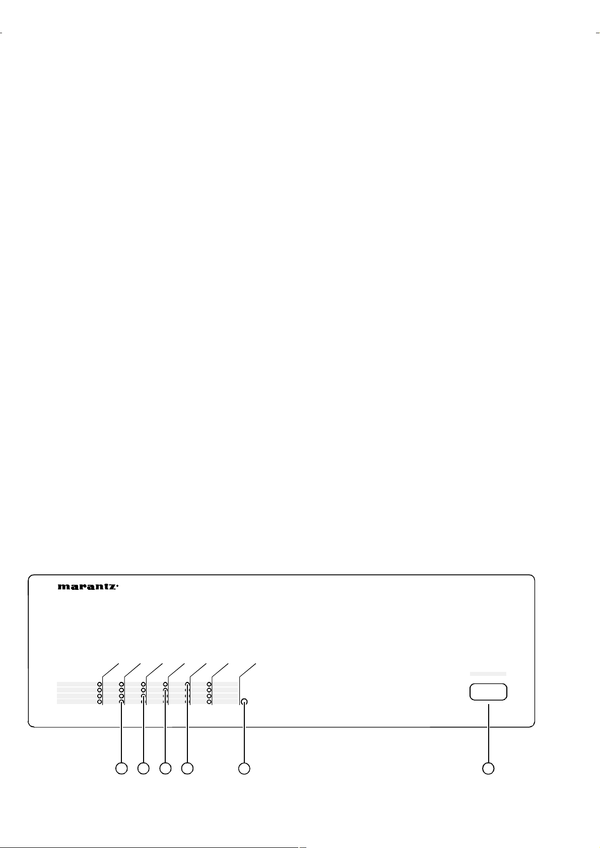
3. NAMES AND FUNCTIONS
1. SIGNAL indicator
The signal present LEDs illuminate at an input level of about
13mVrms (-35.5dBu).
2. PEAK indicator
The clipping LEDs illuminate at an input level of about
870mVrms (+1.0dBu), with all channels driven by 1KHz into
8Ω. This indicates that the signal processing circuitry has
determined output levels to be approaching the available
power supply rails and has begun to “soften” signal peaks.
Actual onset of “hard” clipping depends on audio program
and total load impedance and does not occur until the sig-
nal processing circuitry can no longer compensate, which
means that signal integrity can be maintained even if the
clipping indicators illuminate for short periods of time.
3. THERMAL indicator
The thermal LEDs illuminate when the temperature of any
one of the heat sink extrusions reaches 85 to 90°C. Both
channels of the affected amplifier module will shut off until
the measured temperature drops below about 70°C. The
amplifier should be able to maintain proper operation at
an ambient room temperature of 50°C (122°F) or less with
typical audio program and all channels driven into 4Ω.
6CH POWE R AMPLIF ER MM9360
6
PROTECT
THERMA L
PEAK
SIGNAL
CHANN EL1CHANN EL2CHANN EL3CHANN EL4CHANN EL5CHANN EL
1 2 3 4
POWER
5 6
POWER
OFF ON
4
 Loading...