

Marantz DR-4160 Service Manual

Service
DR4160 /F1N, /U1B
Manual
PLAY/PAUSE
CD RECORDER DR4160
REPEAT
CD TEXT
CD1
DISPLAY
SHUFFLE
/
+
–
LEVEL
CD CHANGE
CD2
CD3
MULTI
DISC
CHANGER
AUTO LEVEL CONTROL
PHONES
LEVEL
CD-TEXT EDITING
RECORD
CD→CD
REC
CDR
AUX
LEVEL
COMPLE CD
NO
REC TYPE
FINALIZE
ERASE
4822 725 25242
3104 125 40100
ON/OFF
STOP
OPEN/
CLOSE
MIC
SERVICING
For servicing DR4160, the sets can be divided into two parts:
1. Except for the Power board (Switched Mode Power Supply) and the CD-R/W module the set has to
be repaired on component level.
2. The Power board and the CD-R/W module will be exchanged completely in case of a failure.
The defective CD-R/W module has to be returned for central repair.
Available circuit descriptions:
The Basics of Compact Disc Recordable/Rewritable
3rd generation Compact Disc Recording
CD Recorder
TEXT
PROG
BALANCE
N
O
T
C
R
TR EDIT
O
G
L
O
J
+–
YES
OPEN/
CLOSE
DR4160
TABLE OF CONTENTS
chapter
Technical Specification and Measurement setup................1-1, 1-2
Location of printed circuit boards............................................1-3
Warnings & Safety..................................................................2-1
Dismantling Instructions.....................................................4-1 to 4-5
Service hints......................................................................5-1 to 5-3
Service Test Program........................................................5-4 to 5-6
BLOCK DIAGRAMS ..........................................................6-1 to 6-5
WIRING DIAGRAM.................................................................6-6
POWER BOARD (for orientation only) ..............................7-3 to 7-4
FRONT BOARD.................................................................7-5 to 7-6
KEY BOARD left.....................................................................7-7
KEY BOARD right...................................................................7-8
Please use this service manual with referring to the user guide (D.F.U) without fail.
修理の際は、必ず取り扱い説明書を準備し操作方法を確認の上作業を行ってください。
HEADPHONE/MICROPHONE BOARD ...........................7-9 to 7-10
chapter
INTERFACE BOARD......................................................7-11 to 7-13
3CDC MODULE................................................................8-1 to 8-9
EXPLODED VIEWS
apparatus..........................................................................10-1
3CDC module...............................................................8-8 to 8-9
MECHANICAL PARTSLIST see Exploded views
ELECTRICAL PARTSLIST...................................................10-2 ff
R
DR4160
437W855010 SIG
First Issue:2000.12

1-1
TECHNICAL SPECIFICATION
General:
Mains voltage:
120V / 60Hz for DR4160/U1B
Power consumption:≤16W
≤ 1W in stand by
Input / Output:
Analog in:
input sensitivity : ≤500mV
rms
max. input voltage : 2,8Vrms
input impedance : 47kΩ
Analog out:
output level : 2V
rms±2dB at no load
output impedance : 200Ω
Microphone in:
input sensitivity : ≤1mV
rms
max. input voltage : 50mVrms
input impedance : 2kΩ
Digital in (acc. IEC958):
input level : 0,5V
pp
input impedance : 75Ω
Digital out (acc. IEC958):
output level : 0,5V
pp
output impedance : 75Ω
Headphone:
output level : 4,4V
pp at no load
output impedance:120Ω
frequency response: 20 - 20.000 Hz ±3dB
distortion : 0,01% at 1 kHz and -6dB output level at 120Ω
channel difference : ≤ 3dB at 1 kHz
channel crosstalk : -50dB at 1kHz
AUDIO PERFORMANCE
3CDC module:
To be measured on ANALOG OUT socket.
frequency response : 20 - 20.000 Hz ±0,6dB
signal/noise ratio : ≥ 115dB (120dB A-weighted)
distortion : -88dB at 1 kHz (-91dB typ.)
channel difference : ≤ 0,5dB at 1 kHz
channel crosstalk : -115dB at 1kHz(-120dB typ.)
de emphasis : 0 or 15/50µs switched automatically by subcode on the disc
laser
output power : 500µW
wave length : 780 ±20nm
CD-RW module:
To be measured on ANALOG OUT socket.
frequency response : 20 - 20.000 Hz ±0,3dB (±1dB recording)
signal/noise ratio : ≥ 95dB (98dB A-weighted)
distortion : -86dB at 1 kHz (-83dB recording)
channel difference : ≤ 0,5dB at 1 kHz
channel crosstalk : -86dB at 1kHz (-74dB recording)
de emphasis : 0 or 15/50µs switched automatically by subcode on the disc
laser (laser class 3B)
output power : 1mW max. during reading
20mW max. during writing
wave length : 780 ±20nm
100V / 50-60Hz for DR4160/F1N
1-2
SYSTEM CODE
RC KEY
y
COMMAND CODE
CD
20 26 12
CDR
BRIGHTNESS
Standby
20 26 71
TRACK INCR.
- 26 114
CD TEXT
20 26 88
1
20 26 01
2
20 26 02
3
20 26 03
4
20 26 04
5
20 26 05
6
20 26 06
7
20 26 07
8
20 26 08
9
20 26 09
TEXT EDIT
20 26 82
0
20 26 00
PROGRAM
20 26 36
NO
20 26 49
YES
20 26 87
PLAY
20 26 53
¡
2
9
20 26 33
™
20 26 32
STOP
20 26 54
5
20 26 50
6
;
20 26 52
PAUSE
20 26 48
SHUFFLE
20 26 28
REPEAT
20 26 29
CD1
20 20 55
CD2
20 20 56
CD3
20 20 57
CDR
26 26 63
RC5 code RC283505, 130300
Remote Control:
RC5 commands
RC283521
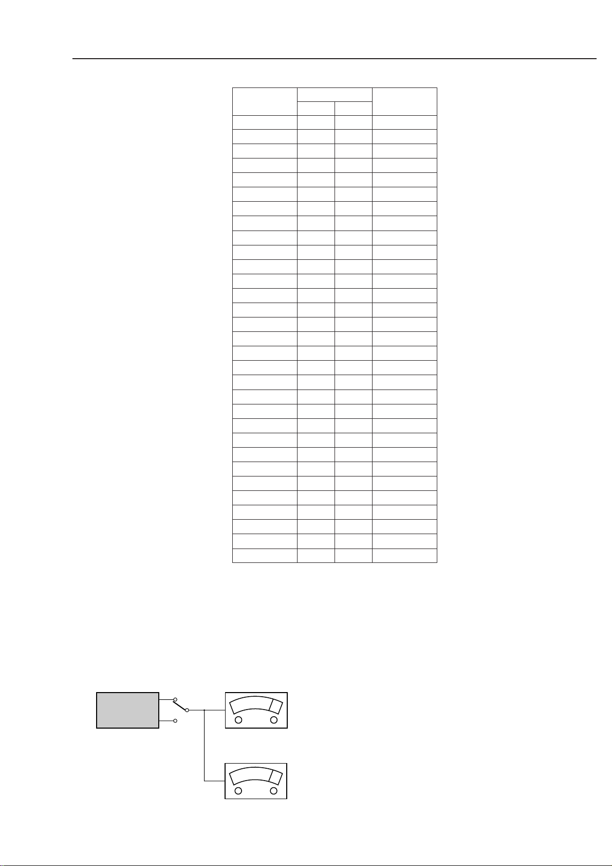
TECHNICAL SPECIFICATION
L
R
LEVEL METER
e.g. Sennheiser UPM550
with FF-filter
S/N and distortion meter
e.g. Sound Technology ST1700B
DUT
CD
Use Audio Signal Disc SBC429 4822 397 30184
(replaces test disc 3)
MEASUREMENT SETUP
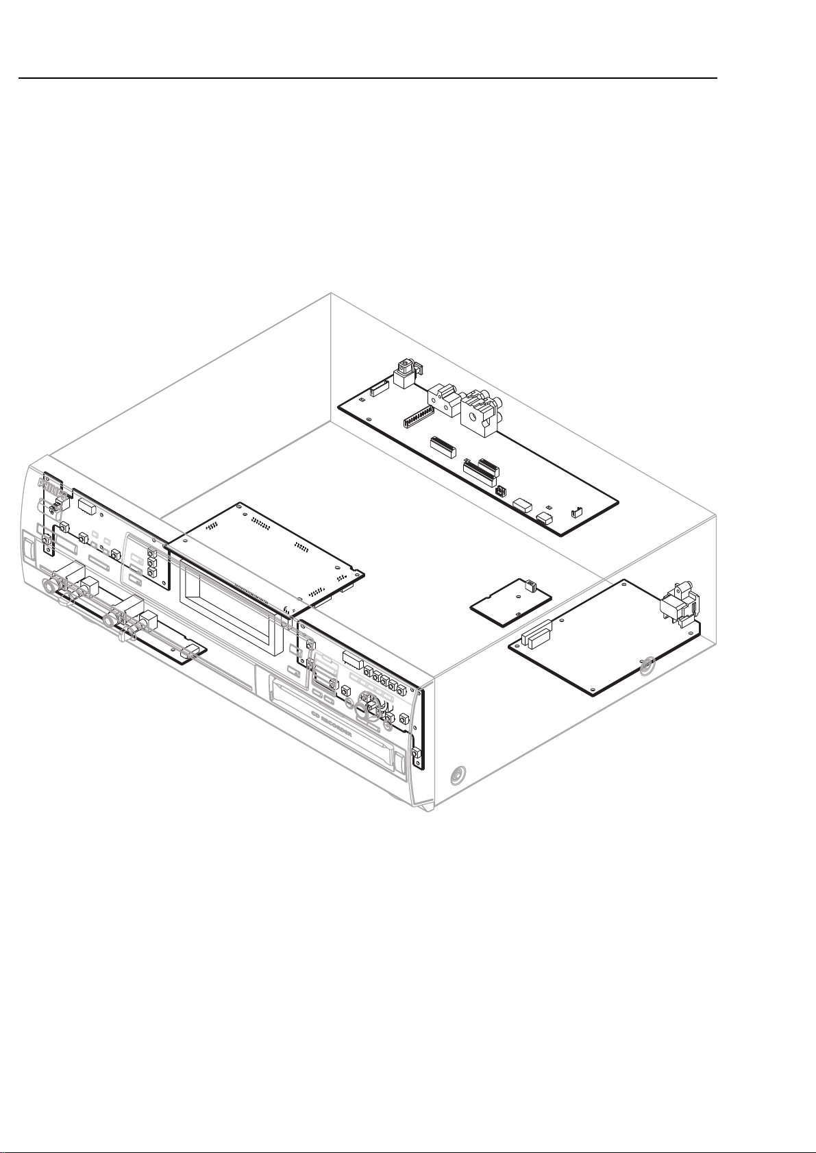
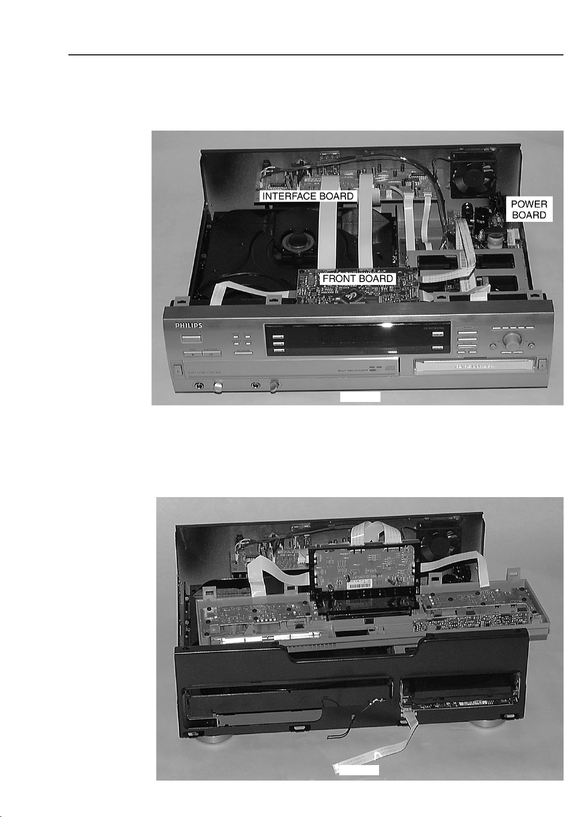
1-3
FRONT BOARD
INTERFACE BOARD
HEADPHONE/MIC BOARD
SWITCHED MODE
POWER SUPPLY
NTC
loccation of pcb´s, 240200
KEY BOARD RIGHT
KEY BOARD LEFT
LOCATION OF PRINTED BOARDS
picture 1
2-1
© WARNING
All ICs and many other semiconductors are susceptible to
electrostatic discharges (ESD). Careless handling during
repair can reduce life drastically.
When repairing, make sure that you are connected with the
same potential as the mass of the set via a wristband with
resistance. Keep components and tools at this potential.
f ATTENTION
Tous les IC et beaucoup d´autres semi-conducteurs sont
sensibles aux décharges statiques (ESD). Leur longévite
pourrait être considérablement écourtée par le fait qu´aucune
précaution nést prise à leur manipulation.
Lors de réparations, s´assurer de bien être relié au même
potentiel que la masse de l´appareil et enfileer le bracelet
serti d´une résistance de sécurité.
Veiller à ce que les composants ainsi que les outils que l´on
utilise soient également à ce potentiel.
d WARNUNG
Alle ICs und viele andere Halbleiter sind empfindlich
gegenüber elektrostatischen Entladungen (ESD).
Unsorgfältige Behandlung im Reparaturfall kann die
Lebensdauer drastisch reduzieren.
Sorgen Sie dafür, daß Sie im Reparaturfall über ein Pulsarmband mit Widerstand mit dem Massepotential des
Gerätes verbunden sind.
Halten Sie Bauteile und Hilfsmittel ebenfalls auf diesem
Potential.
ñ WAARSCHUWING
Alle IC´s en vele andere halfgeleiders zijn gevoelig voor
electrostatische ontladingen (ESD).
Onzorgvuldig behandelen tijdens reparatie kan de levensduur
drastisch doen vermindern. Zorg ervoor dat u tijdens reparatie
via een polsband met weerstand verbonden bent met hetzelfde
potentiaal als de massa van het apparaat.
Houd componenten en hulpmiddelen ook op ditzelfde potentiaal.
i AVVERTIMENTO
Tutti IC e parecchi semi-conduttori sono sensibili alle scariche
statiche (ESD).
La loro longevità potrebbe essere fortemente ridatta in caso di
non osservazione della più grande cauzione alla loro
manipolazione. Durante le riparationi occorre quindi essere
collegato allo stesso potenziale che quello della massa
delápparecchio tramite un braccialetto a resistenza.
Assicurarsi che i componenti e anche gli utensili con quali si
lavora siano anche a questo potenziale.
©
Safety regulations require that the set be restored to its
original condition and that parts which are identical with
those specified be used.
Safety components are marked by the symbol
i
Le norme di sicurezza estigono che l´apparecchio venga
rimesso nelle condizioni originali e che siano utilizzati i
pezzi di ricambiago identici a quelli specificati.
Componenty di sicurezza sono marcati con
ñ
Veiligheidsbepalingen vereisen, dat het apparaat in zijn
oorspronkeliijke toestand wordt teruggebracht en dat
onderdelen, identiek aan de gespecificeerde, worden toegepast.
De Veiligheidsonderdelen zijn aangeduid met het symbool
s Varning !
Osynlig laserstrålning när apparaten är öppnad och
spärren är urkopplad. Betrakta ej strålen.
∂ Advarsel !
Usynlig laserstråling ved åbning når sikkerhedsafbrydere
er ude af funktion. Undgå udsaettelse for stråling.
ß Varoitus !
Avatussa laitteessa ja suojalukituksen ohitettaessa olet alttiina
näkymättömälle laserisäteilylle. Älä katso säteeseen !
f
"Pour votre sécurite, ces documents doivent être utilisés par
des spécialistes agréés, seuls habilités à réparer votre
appareil en panne".
ESD
SAFETY
d
Bei jeder Reparatur sind die geltenden Sicherheitsvorschriften zu beachten. Der Originalzustand des Gerätes
darf nicht verändert werden. Für Reparaturen sind Originalersatzteile zu verwenden.
Sicherheitsbauteile sind durch das Symbol markiert.
f
Les normes de sécurité exigent que l`appareil soit remis
à l`état d`origine et que soient utilisées les pièces de
rechange identiques à celles spécifiées.
Les composants de sécurité sont marqués
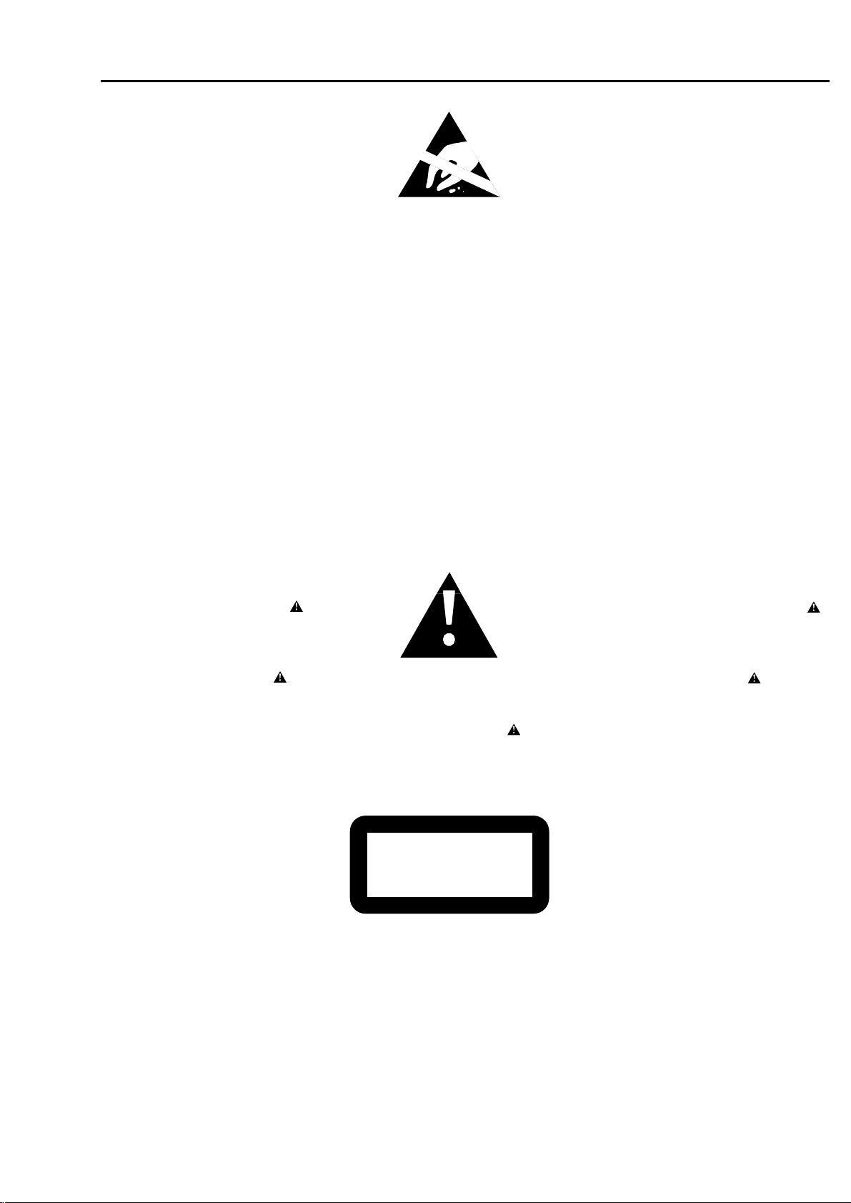
CLASS 1
LASER PRODUCT
©
DANGER: Invisible laser radiation when open.
©
After servicing and before returning the set to customer
perform a leakage current measurement test from all
exposed metal parts to earth ground, to assure no
shock hazard exists.
The leakage current must not exceed 0.5mA.
AVOID DIRECT EXPOSURE TO BEAM.
©
AVAILABLE ESD PROTECTION EQUIPMENT :
anti-static table mat large 1200x650x1.25mm 4822 466 10953
small 600x650x1.25mm 4822 466 10958
anti-static wristband 4822 395 10223
connection box (3 press stud connections, 1MΩ) 4822 320 11307
extendible cable (2m, 2MΩ, to connect wristband to connection box) 4822 320 11305
connecting cable (3m, 2MΩ, to connect table mat to connection box) 4822 320 11306
earth cable (1MΩ, to connect any product to mat or to connection box) 4822 320 11308
KIT ESD3 (combining all 6 prior products - small table mat) 4822 310 10671
wristband tester 4822 344 13999
WARNINGS & SAFETY

4-1
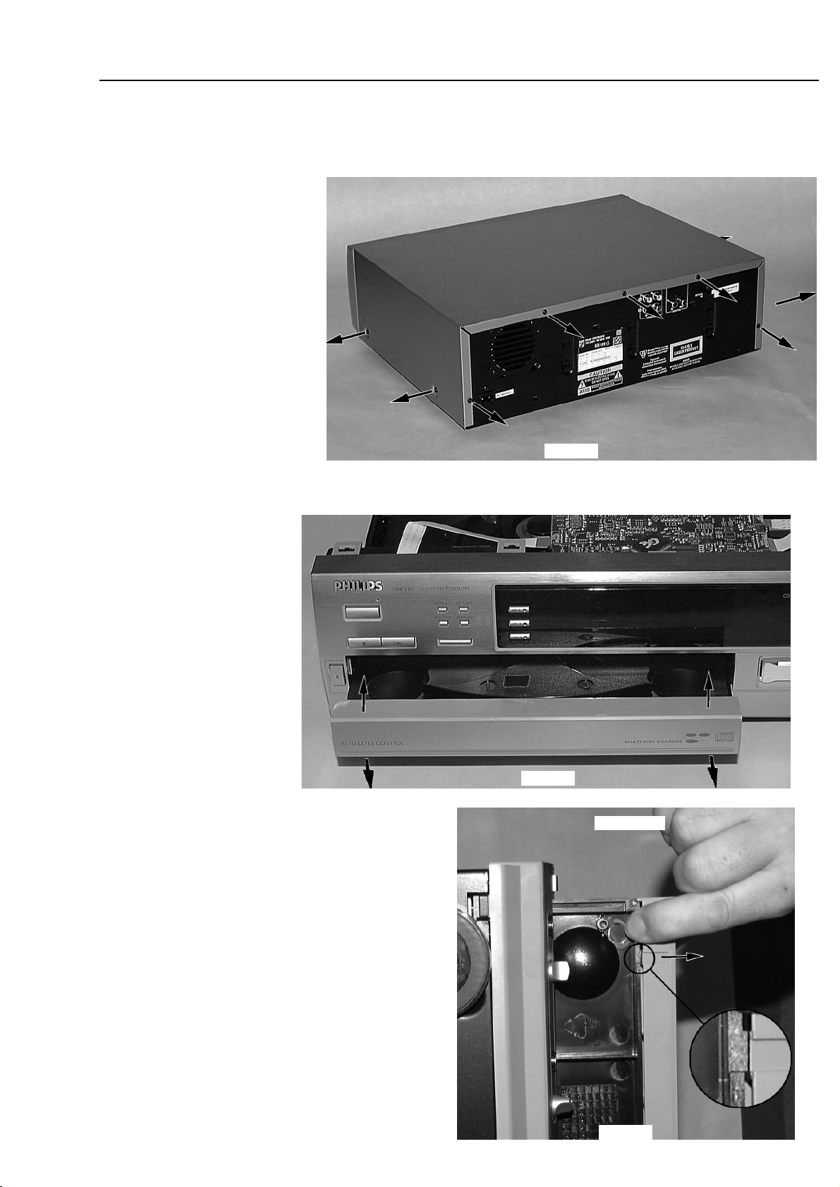
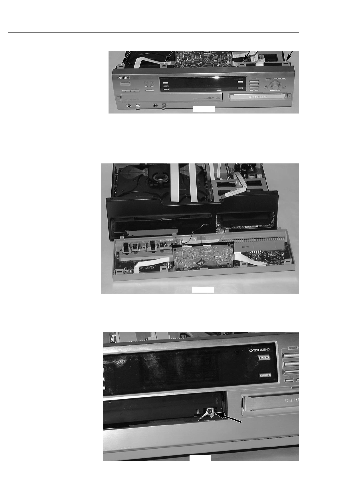
DISMANTLING INSTRUCTIONS
Dismantling the
Top Cover
picture 2
• Remove 9 screws as shown in picture 2.
• Raise top cover at the rear and pull it backwards.
Dismantling the
Tray Cover
picture 3
picture 4
bottom view
• To release the cover from the catch on the tray pull it
frontwards on bottom side as shown in picture 4.
• Pull the cover up.
4-2
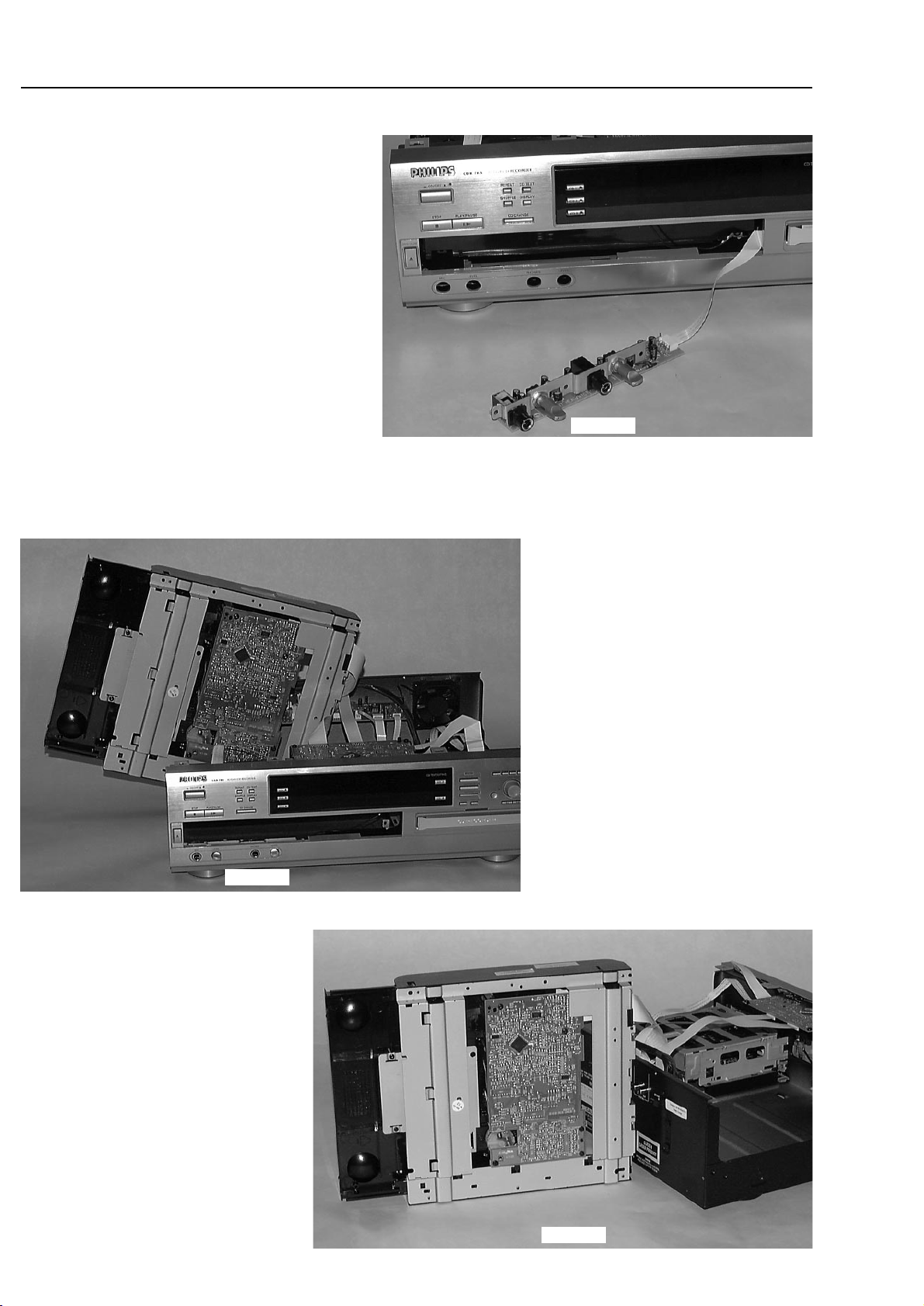
DISMANTLING INSTRUCTIONS
Dismantling the
Front Cabinet
Dismantling the
3CDC module
picture 5
picture 6
• Remove tray cover first →see description before.
• Disconnect flexfoil cables to interface board and CDR module.
• Release catches on top as shown in picture 5 and turn
front cabinet away.
Take care of the flexfoil cables connecting the key boards!
• Place front cabinet as shown in picture 6.
• Remove 2 screws on front side first
→ see pictures 7.
picture 7
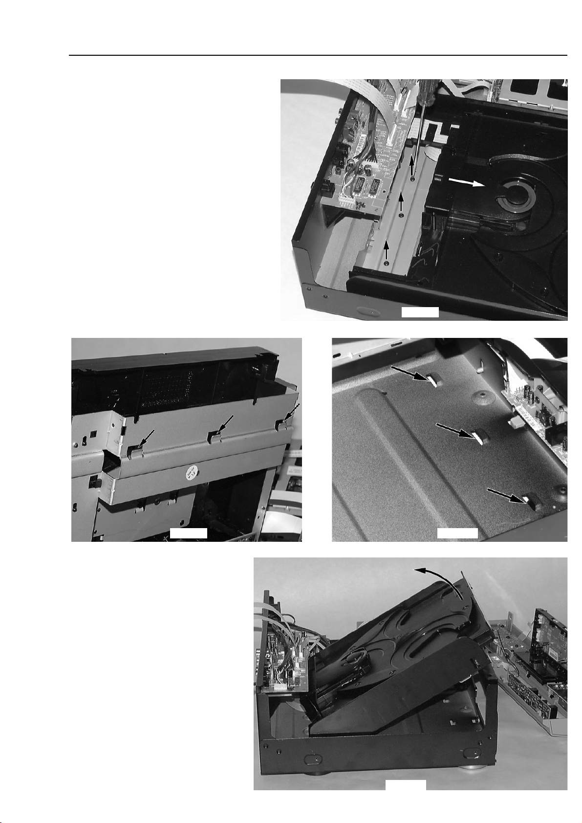
4-3
Dismantling the
CDC module
continued
DISMANTLING INSTRUCTIONS
• Dismantle front cabinet as described before.
• Move the tray a few centimetres out to get access
to the fastening screws at the rear.
• Remove the 3 screws as shown in picture 8.
• Put the tray back and move the complete module
backwards to release catches on bottom cabinet.
→ for orientation see picture 9 and 10.
picture 8
picture 9
picture 11
• Pull the module on front side up and turn it
out as shown in picture 11.
• Put the module to a proper service position.
→ see also chapter SERVICE HINTS
• To get the set operating mount front cabinet
and connect flexfoil cables to front board
again.
picture 10

4-4
DISMANTLING INSTRUCTIONS
Dismantling the
CDR module
• Remove 3 screws as as indicated in picture 12.
• Disconnect all cables.
• Move the module backwards to release the catch on
pos. 205 (see exploded view)
• Raise the module on the rear and turn it out.
picture 12
picture 13
Fixation by a catch on
right front-side

4-5
DISMANTLING INSTRUCTIONS
Dismantling the
Power board
• Disconnect all cables.
• Remove 3 screws as as indicated in picture 14.
• Release the catches on the plastic supports.
• Move the board backwards to release the catch on
left front-side.
• Lift the module on the rear and turn it out.
remark: space to CDR module will be very tight
picture 14
picture 15
Fixation by a catch on left
rear-side
5-1
SERVICE HINTS
SERVICE TOOLS
TORX T10 screwdriver with shaftlength 150mm ......................................4822 395 50423
TORX screwdriver set SBC 163..............................................................4822 295 50145
Audio signal disc SBC 429......................................................................4822 397 30184
Playability test disc SBC444...................................................................4822 397 30245
Test disc 5 (disc without errors) +
Test disc 5A (disc with dropout errors, black spots and fingerprints)
SBC 426/426A ....................................................................4822 397 30096
Burn in test disc (65 min. 1kHz signal at -30dB level without "pause")...4822 397 30155
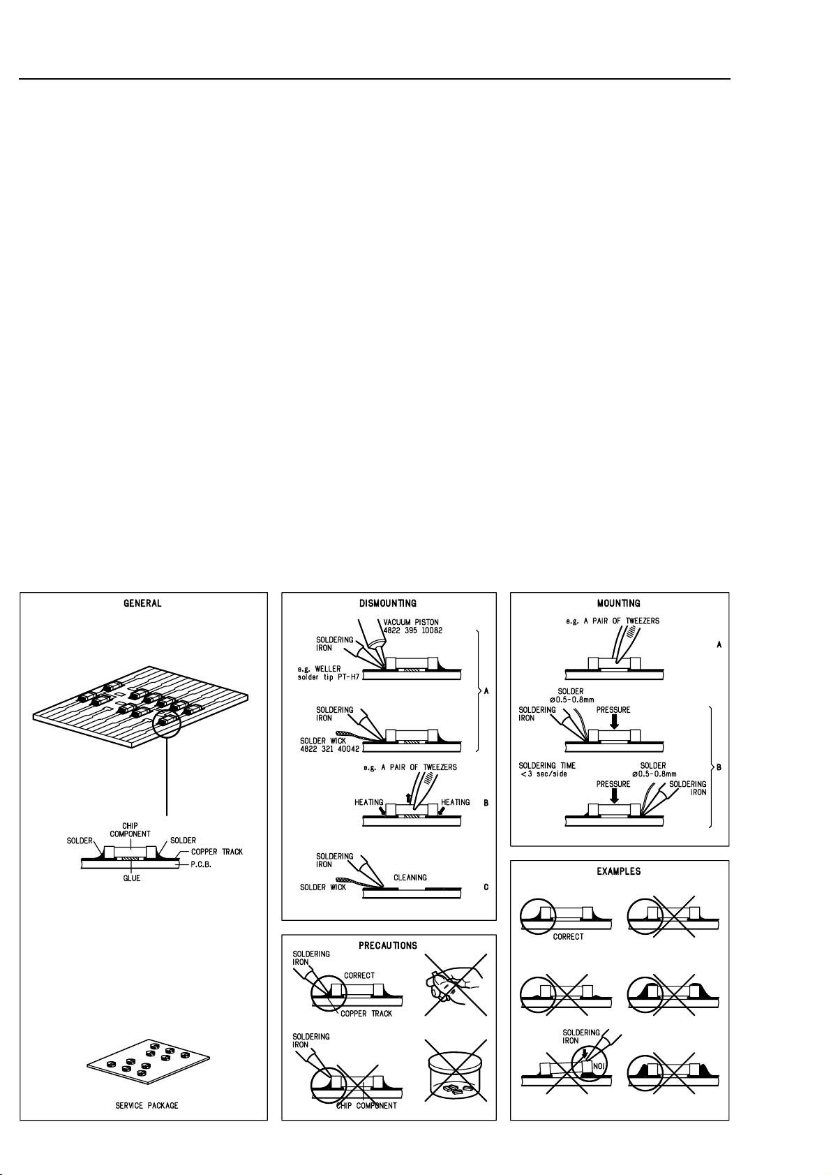
HANDLING CHIP COMPONENTS
5-2
SERVICE HINTS
General Service position
For repairs on: Front Board
Power Board
Interface Board
Service position
Key Boards
After dismantling the front cabinet as described in
chapter 4-2 the front unit can be placed on 3CDC- and
CDR module and be re-connected again.
picture 16
picture 17
5-3
SERVICE HINTS
Service position
3CDC Module
Service position
Headphone/Microphone Board
picture 18
picture 20
picture 19
• Dismantle front cabinet as described in chapter 4-2.
• Dismantle Headphone/Microphone Board and put it
through the opening for the 3CDC-tray in front
cabinet.
• Mount front cabinet provisional and re-connect
flexfoil cables to Front Board.
Dismantle the 3CDC module as described
in chapter 4-2 to 4-3 and place it in the
desired service position.
5-45-4
Display shows
version number
of the µP - software.
CDR785 servtest CDC, 070400
*
To leave Service Testprogram plug mains cord off.
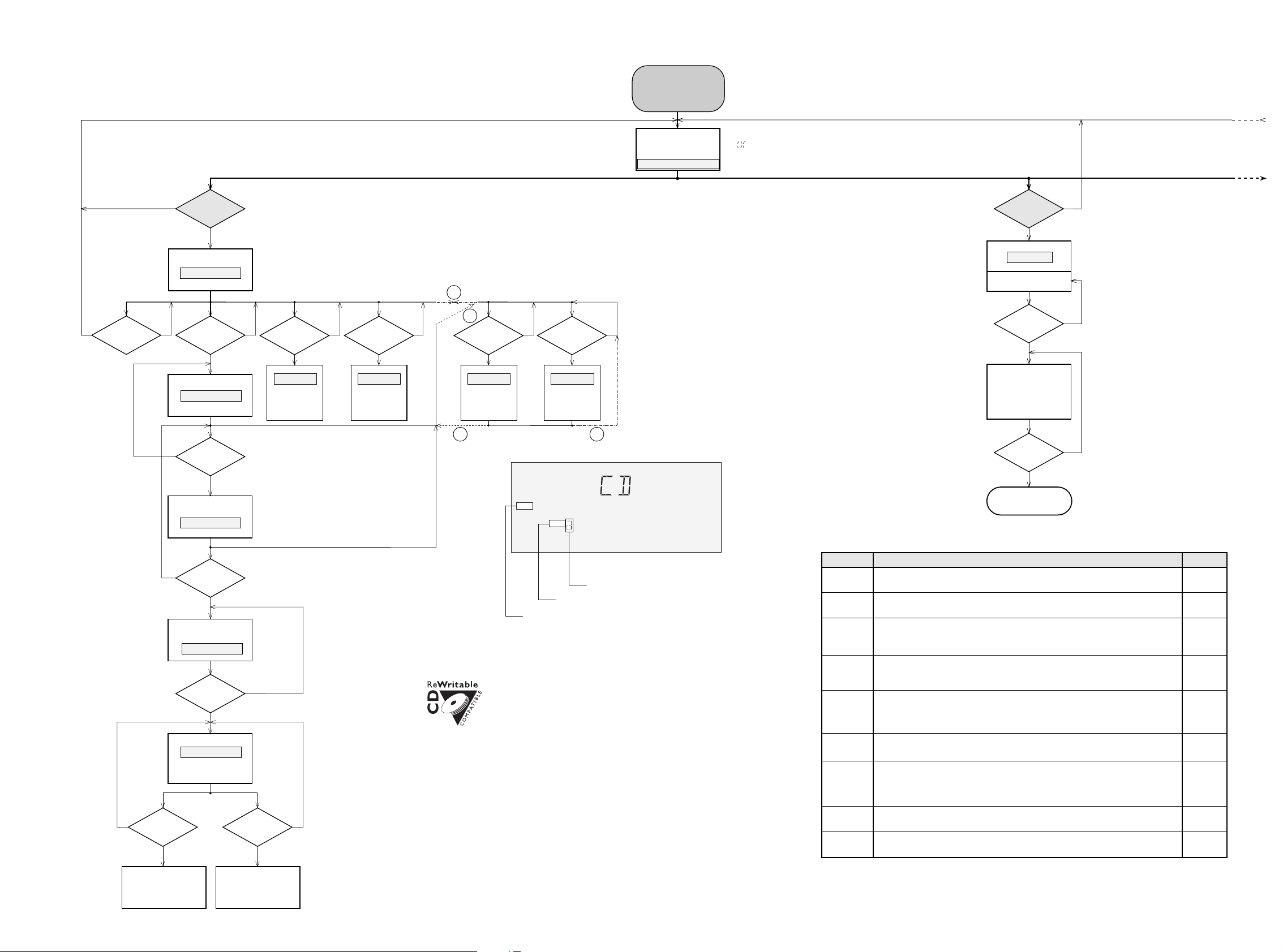
SERVICE TESTPROGRAM
CD-CHANGER MODULE
The
CD PLAY TEST
is intended to be used
for continuously playing a disc in order to
detect intermittent or not reproducible
failures. The error code indicates where
the failure can be found.
1)
Y
CD PLAY TEST
1)
N
CD is in normal
PLAY
mode.
In case of failures
error codes acc. table 1
will be indicated
on the display.
MAINS CORD
plugged off?
N
Y
Display shows:
STANDBY
for 5s.
Set is switched to
Standby mode.
PLAY
button
pressed?
N
Y
Exit Service Testprogram
CD3
button
pressed?
stands for Service mode
stands for version number
of the software used in the
front µP.
To enter Service
Testprogram hold
CD yCD & NO
buttons
depressed while
plugging mainscord in.
On/Off switch in pos.
ON
VXX
S
S-CDR785-VXX
Y
Display shows
see also fig. 1
PLAY
button
pressed?
STOP
button
pressed?
NEXT
6 button
pressed?
PREV
5 button
pressed?
REC LEVEL
button
pressed?
PROG
button
pressed?
Slide moves
outside as long as
button is held
depressed.
Slide moves
inside as long as
button is held
depressed.
Disc motor turns
counter clockwise
as long as button
is held depressed.
(brake)
Disc motor turns
clockwise
as long as button
is held depressed.
(accelerate )
Y
Y
YY
YY
N
N
NN
N
NN
A
FOCUS found?
Y
N
Display shows
objective moves up&down
Display shows
NEXT
6 button
pressed?
Y
N
Display shows
→ Play mode
MUTE is switched off
(single speed)
PREV
5 button
pressed?
Y
N
CUE - mode
jumps in steps of
16 tracks forwards
as long as button
is hold depressed.
FOCUS search
RADIAL test
DISC SERVO
REVIEW - mode
jumps in steps of
16 tracks backwards
as long as button
is hold depressed.
SLIDE testDISC MOTOR test
SERVO test
Slide can be activated in FOCUS test too:
check if Focus functions over the whole disc area
PLAY
button
pressed?
Y
N
B
B A
Purpose of RADIAL test:
To check if the Audio signal is reproduced.
Subcode info is ignored during this test →
If the CD player functions well in this testmode,
but not in the normal Play mode check quality
of the eye-pattern signal.
Display shows absolute playing time of the disc
in order one can determine position of the slide.
If the playing time is not shown (display flickers)
the pickup is possibly out of the program area of
the disc. Press
Next
or
Prev
to move slide inside.
Tray (open/close button) and Carousel
(CD1, 2, 3 buttons)
work as in normal mode.
After activation of the tray or the carousel
program returns to SERVO test.
STOP
button pressed in
FOCUS- or RADIAL-test
returns to SERVO-test
Since the CD-RW reflects much less light than an ordinary CD-DA
the gain of the HF-amplifier stage and the sensitivity of the ADC inside
the Signal Processor must be increased to find the focus point.
In normal play mode high/low - gain is switched automatically.
In Service Test Mode, with the
TRACK EDIT
button, the gain/sensitivity can be
toggled manually between high or low as soon as the SERVO test has been entered.
When the set is switched to high gain, RW flag is indicated on the display.
NOTE: If sensitivity is switched to
CDRW
the set
might not work with normal Audio CDs!
In the steps
SERVO test
and
FOCUS search
the disc speed can be toggled manually
between single speed (1x) and double speed (2x) with the
TEXT
button.
Flag 1 or 2 of the music calendar indicates the actual speed.
indicates speed -
single speed
or
double speed
note: when
double speed
is set output is muted in RADIAL test
indicates sensitivity -
CD
or
CDRW
indicates the chosen disc - 1, 2 or 3
Y
N
Disc speeds up.
Display shows
CD SERVO TEST
CD1
button
pressed?
N
PLAY
button
pressed?
Single/double speed
Display shows: Display shows: Display shows: Display shows:
CD
FOC ERR
CCW CW SLD O SLD I
FOC OK
DISC OK
RDL
fig. 1
CD
RW
1 2
set continues operation, message remains on the display until next error occurs
or any key is pressed.
Error number Error type
Error type:
Error description
E1000 Focus Error
Triggered when the focus is lost for more than 250ms while playing the CD.
E1006 Subcode Error
No valid subcode for 300ms during
PLAY
.
Slide-out error
Generated when the inner-switch did not open within approx. 250ms when the pick up is
moved from the inner position outside. Inner-switch or slide motor problems.
E1002
E1003
Slide-in error
Generated when the inner-switch did not close within approx. 6s when the pick up is
moved inside. Inner-switch or slide motor problems.
W
E1020 Focus Search Error
Triggered when the focus could not be found within 4s when starting up the CD.
F
W
W
E1001 Radial error
Triggered when the radial servo is not on track for a certain time during playing the CD.
W
W
W
W
W = Warning →
F = Fatal Error
→ set stops operation, message remains on the display.
CD ERROR CODES
table 1
E1005 Jump error.
Triggered when the servo processor counts too less tracks in a defined time during JUMPS.
This can be caused by a disturbed HF-signal (the tracks cannot be recognized exactly),
slide motor problems, track servo problems or scratched discs.
E1008 Disc motor error
Generated when the CD could not reach 75% of speed during startup within 1,2s.
W
E1007 PLL lock error
When no valid subcode was found within 300ms PLL is checked. If PLL is locked E1006
will be indicated else E1007 and the servo is stopped and restarted once again to recover
(as if the user would have pressed
STOP
and then
PLAY
immediately).
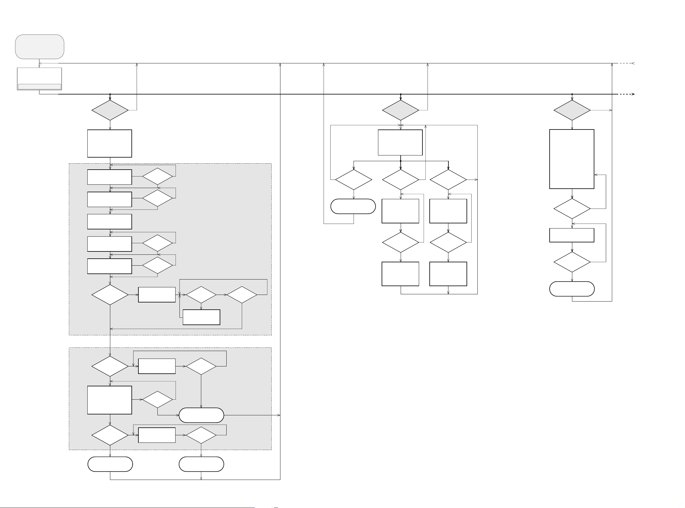
5-5 5-5
*
To leave Service Testprogram plug mains cord off.
Display shows
version number
of the µP - software.
OPEN/CLOSE
button
pressed?
FINALIZE
button
pressed?
N
Y
N
Y
NEXT
6
button
pressed?
N
Y
PREV
5
button
pressed?
N
Y
STOP
button
pressed?
N
Y
CDR MECHANICAL TEST CDR DC-ERASE MODE
FOCUS TEST
Objective moves
continuously up/down.
SLIDE TEST TRAY TEST
Display shows:
BUSY
Display shows:
BUSY
for visual inspection only
OPEN/CLOSE
button
pressed?
N
Y
Slide moves
continuously in/out.
Display shows:
OPENED
(even when tray is blocked)
Tray opens.
Display shows:
CLOSE
(even when tray is blocked)
Tray closes.
Dependent on the
moving direction,
slide moves to inner
or outer end position.
Exit Mech. Testprogram
SERVICE TESTPROGRAM
CDR MODULE
stands for Service mode
stands for version number
of the software used in the
front µP.
To enter Service
Testprogram hold
CD yCD & NO
buttons
depressed while
plugging mainscord in.
On/Off switch in pos.
ON
CDR785 servtest CDR,160200
CDR
button
pressed?
TEST O.K.?
NN
N
Y
Y
N
Y
Y
Y
Display shows for 2s each:
• Software version of DASP
(flash ROM 7703)
• Software version of
basic engine processor
(flash EPROM 7208)
CDR ELECTRICAL TEST
ERASE
button
pressed?
N
Y
Disc erased?
N
Y
N
Y
Insert CD-DA disc
before starting the test
MODULE
INFORMATION
MAIN BOARD DIAGNOSTIC
CDR - LOADER TEST
DRAM TEST 7702
Display shows:
DTST1
CHECKSUM TEST 7703
Display shows:
DTST2
ERASE TEST 7208
Display shows:
DTST3
ADC/DAC TEST 7406
Display shows:
DTST4
COMMUNICATION TEST
(DSA-BUS)
Display shows:
DTST5
Display shows:
DERR
n
n=number of failed test
Display shows next error
FFWD
6 button
pressed?
N
Y
FFWD
6 button
pressed?
Y
FFWD
6 button
pressed?
Y
FFWD
6 button
pressed?
Y
FFWD
6 button
pressed?
all errors shown?
N
N
N
N
FFWD
6 button
pressed?
Y
N
TEST O.K.?
NN
Y
Y
Display shows:
BERR 1
FFWD
6 button
pressed?
CD-DA disc
inserted?
Display shows actual
playing time.
The test is performed by
playing 5s at beginning,
5s in the middle and 5s at
the end of the disc.
N
Y
Display shows:
NO DISC
FFWD
6 button
pressed?
Exit CDR electrical Test
Complete disc will be
erased with double speed.
(starting from PMA-area
up to and including
ATIP leadout area)
The display shows the
countdown of the
remaining time required
to complete the operation:
ER mm ss
Display shows:
PASSED
mm: remaining minutes
ss: remaining seconds
STOP
button
pressed?
Exit DC-ERASE Mode
Note: With the DC-Erase mode the CD-RW can be
changed back in its original state, like a new disc.
Stopping the erase-function by switching power off
will leave the disc in an unpredictable status!
Exit CDR electrical Test Exit CDR electrical Test
S-CDR785-VXX
VXX
S
 Loading...