

Marantz AV8802A Service Manual
Service
AV8802 /
AV8802A /
U1B/N1B/FB
U1B/N1B/K1B/FB
Manual
AV Pre Tuner
For purposes of improvement, specications and design are subject to change without notice.
•
Please use this service manual with referring to the operating instructions without fail.
•
Some illustrations using in this service manual are slightly different from the actual set.
•
Ver. 8
AV8802 / AV8802A
Copyright 2017-2014 D&M Holdings Inc. All rights reserved.
S0044V08DM/DG1709
START::|UNA0JkWjR3Mx1oB5rVBS0Q==|RTIIUTkj6DN1dijOWUrkPkhbrB5kROvEpxrZCSxikOI=|lYV/KaXVYq6E/Xaks5O/YA==|::END
WARNING: Violators will be prosecuted to the maximum extent possible.
Please refer to the
MODIFICATION NOTICE.

CONTENTS
ABOUT THIS MANUAL
What you can do with this manual ............................................3
Using Adobe Reader (Windows version) ..................................4
SAFETY PRECAUTIONS
NOTE FOR SCHEMATIC DIAGRAM
NOTE FOR PARTS LIST
TECHNICAL SPECIFICATIONS
DIMENSION
Precautions During Service
Initializing This Unit .................................................................10
Service Jigs .............................................................................10
DISASSEMBLY
1. CX870 ASSY for CX870 model only ..................................14
2. FRONT PANEL ASSY ........................................................14
3. HDAM ASSY ......................................................................15
4. SMPS ASSY .......................................................................15
5. POWER TRANS ................................................................16
6. BACK PANEL ASSY ...........................................................17
SPECIAL MODE
Special Mode Conguration Buttons .......................................18
1. Version Display Mode ........................................................19
2. PANEL / REMOTE LOCK Selection Mode ......................... 23
3. Selection Modes for Service-related Operations ................24
DIAGNOSTIC PATH DIAGRAM .........................................29
4. Additional Source mode .....................................................70
5. CX870 / CY920 Reboot Mode ............................................71
6. CX870 / CY920 Initialization Mode ....................................71
JIG FOR SERVICING
Procedure after Replacing the Microprocessor, etc.
Firmware Update Procedure
1. Updating by USB ................................................................74
2. Updating by DPMS .............................................................84
SURROUND MODES AND PARAMETERS
TROUBLE SHOOTING
1. POWER ..............................................................................94
2. Analog video ......................................................................95
3. HDMI/DVI ...........................................................................97
4. AUDIO ................................................................................99
5. Network/Bluetooth/USB ...................................................101
6. SMPS ...............................................................................107
Audio Check PASS
CLOCK FLOW & WAVE FORM IN DIGITAL BLOCK
LEVEL DIAGRAM
GND DIAGRAM
POWER DIAGRAM
CPU DIAGRAM
...............................................................................9
.............................................................3
..........................................................6
.........................................7
...........................................................7
................................................9
...................................................10
........................................................................11
......................................................................18
..............................................................72
..........74
..................................................74
............................91
............................................................94
..............................................................109
...........11 0
.................................................................. 111
.....................................................................11 9
................................................................120
......................................................................122
PRINTED WIRING BOARDS
SCHEMATIC DIAGRAMS (1/38)
SCH01_DIGITAL CONNECT ................................................133
SCH02_DIR ADC ZONEDAC ...............................................134
SCH03_AUDIO PLD .............................................................135
SCH04_DSP1 .......................................................................136
SCH05_DSP2 .......................................................................137
SCH06_DSP3 .......................................................................138
SCH07_DSP4 .......................................................................139
SCH08-1_MAIN CPU_OLD ..................................................140
SCH08-2_MAIN CPU_NEW .................................................141
SCH09_SUB CPU .................................................................142
SCH10_DECODER ...............................................................143
SCH11-1_HDMI SW1 AV8802 ONLY ....................................144
SCH11-2_HDMI SW1 AV8802A ONLY ..................................145
SCH12-1_HDMI SW2 AV8802 ONLY ....................................146
SCH12-2_HDMI SW2 AV8802A ONLY .................................147
SCH13_IP SCALER ..............................................................148
SCH14_IP SCALER DDR .....................................................149
SCH15-1_VIDEO PLD AV8802 ONLY ..................................150
SCH15-2_VIDEO PLD AV8802A ONLY ................................151
SCH16-1_HDMI RX TX AV8802 ONLY .................................152
SCH16-2_HDMI RX TX AV8802A ONLY ...............................153
SCH17-1_HDMI SUPPLY AV8802 ONLY ..............................154
SCH17-2_HDMI SUPPLY AV8802A ONLY ...........................155
SCH18-1_NETWOR AV8802 ONLY ......................................156
SCH18-2_NETWOR AV8802A ONLY_OLD ..........................157
SCH18-3_NETWOR AV8802A ONLY_NEW .........................158
SCH19-1_MAIN DAC ............................................................159
SCH19-2_MAIN DAC ............................................................160
SCH20-1_ZONEDAC ADC ...................................................161
SCH20-2_ZONEDAC ADC ...................................................162
SCH21_REAR USB ..............................................................163
SCH22_AUDIO VIDEO CONNECT ......................................164
SCH23_AUDIO VOLUME .....................................................165
SCH24_PREOUT ..................................................................166
SCH25_VIDEO SELECTOR .................................................167
SCH26_CONNECT ...............................................................168
SCH27_HDAM XLR-AMP .....................................................169
SCH28_XLR IN_REMOTE IO_232C ....................................170
SCH29_FRONT HDMI_USB .................................................171
SCH30_FRONT ....................................................................172
SCH31_HDAM CONNECT ...................................................173
SCH32_PHONO ...................................................................174
SCH33_SMPS ......................................................................175
SCH34_XLR OUT1 ...............................................................176
SCH35_XLR OUT2 ...............................................................177
SCH36_XLR OUT3 ...............................................................178
SCH37_CX870 CONNECT AV8802 ONLY ...........................179
SCH38_BT MODULE AV8802 ONLY ....................................180
EXPLODED VIEW
PACKING VIEW
SEMICONDUCTORS
1. IC's ...................................................................................183
2. FL DISPLAY .....................................................................205
.................................................................181
.....................................................................182
.................................................123
...........................................133
.............................................................183
2
ABOUT THIS MANUAL
Read the following information before using the service manual.
What you can do with this manual
Search for a Ref. No. (phrase)
(Ctrl+Shift+F)
You can use the search function in Acrobat Reader to
search for a Ref. No. in schematic diagrams, printed
wiring circuit diagrams, block diagrams, and parts
lists.
1.Press
• The Search window appears.
2.EntertheRef.No.youwanttosearchforinthe
Search window, and then click the
•A list of search results appears.
Ctrl+Shift+F
Shift
Ctrl
onthekeyboard.
F
Search
button.
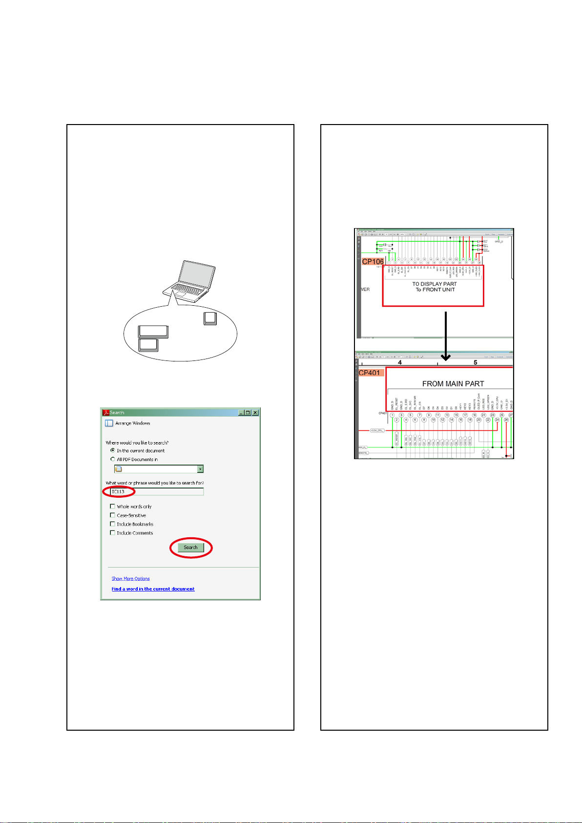
Jump to the target of a schematic
diagram connector
Click the Ref. No. of the target connector in the red
box around a schematic diagram connector.
•The screen jumps to the target connector.
CP401
v
CP106
3.Click an item on the list.
• The screen jumps to the page for that item, and the
searchphraseisdisplayed.
•Pagemagnicationstaysthesameasbeforethe
jump.
3
Using Adobe Reader (Windows version)
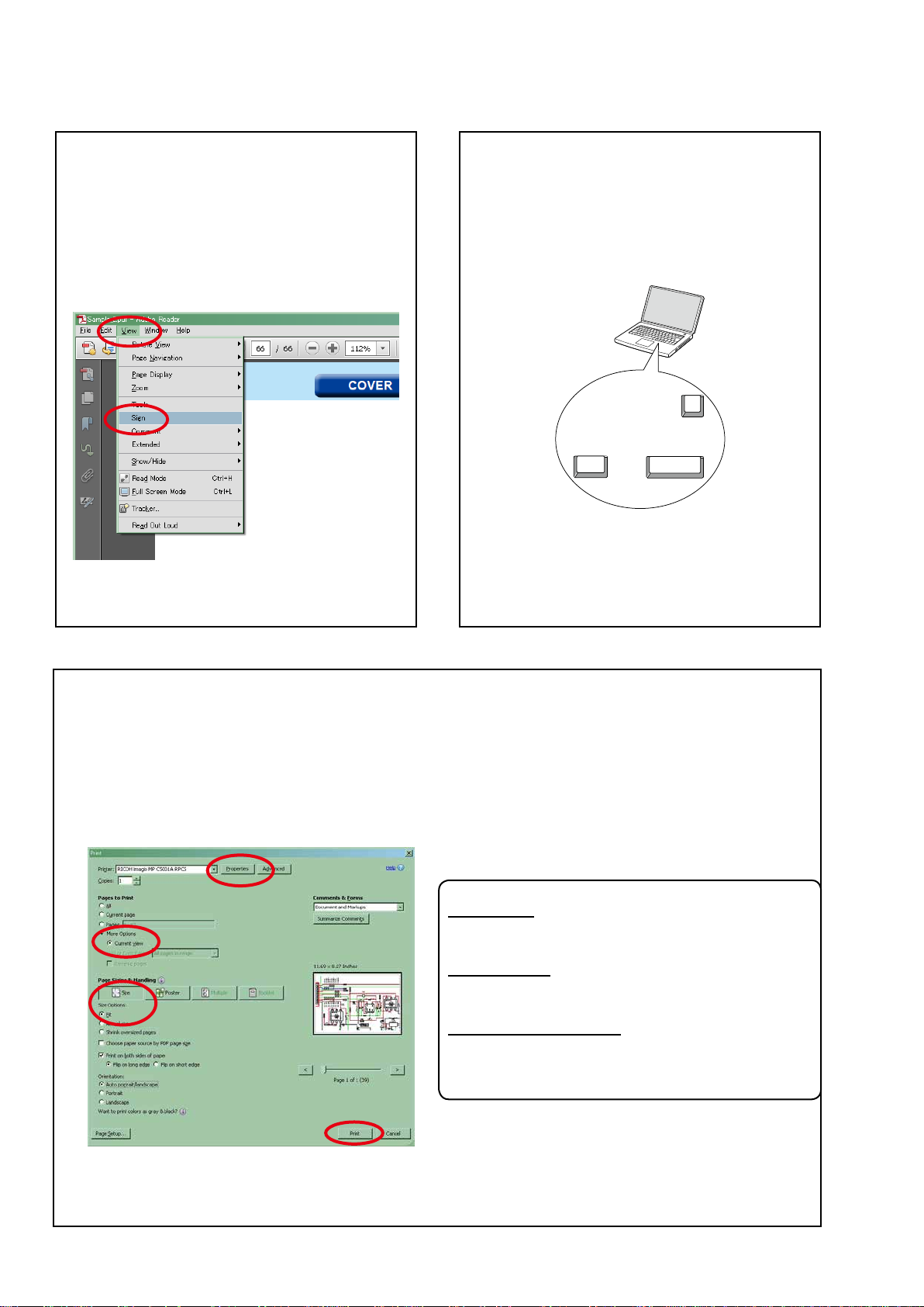
Add notes to this data (Sign)
TheSignfunctionletsyouaddnotestothedatain
this manual.
Savetheleonceyouhavenishedaddingnotes.
[Example using Adobe Reader X]
"View"
On the
• The Sign pane appears.
[Example using Adobe Reader 9]
On the
menu, click
"Document"
"Sign"
menu, click
.
"Sign"
.
Magnify schematic / printed circuit
board diagrams - 1
(Ctrl+Space, mouse operation)
Ctrl+Space
Press
mousetoselecttheareayouwanttoview.
• Theselectedareaismagnied.
• Whenyouwanttomovetheareashown,hold
Space
down
• Whenyouwanttoshowafullpageview,press
Ctrl+0
onthekeyboard.
onthekeyboardanddragthe
0
Ctrl Space
and drag the mouse.
Print a magnied part of the manual
ThePropertiesdialogboxandfunctionswillvarydependingonyourprinter.
1. Dragthemousetomagnifythepartyouwanttoprint.
2. On the
3. CongurethefollowingsettingsinthePrintdialogbox.
"File"
menu, click
"Print"
.
• Properties
Click this button and check that the printer is set to a
suitable paper size.
• Page to print
Select the following checkbox.
More Options
"
• Page Sizing & Handling
Select the following checkbox.
Size
"
Size Options
" / "
Current View
" : "
" : "
Fit
"
"
4. Click the
Print
button to start printing.
4
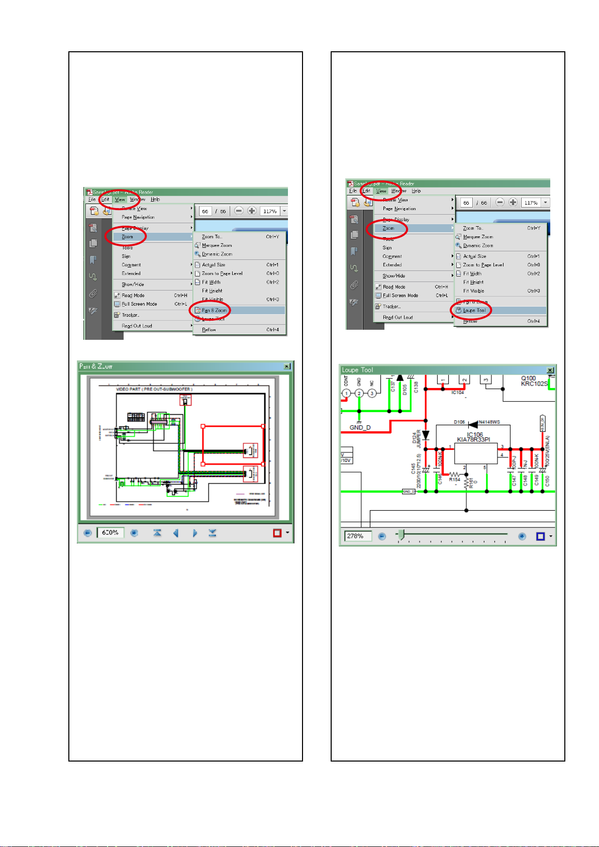
Magnify schematic / printed circuit
board diagrams - 2
(Pan & Zoom function)
ThePan&Zoomfunctionletsyouseewhichpartof
amagnieddiagramisbeingshowninaseparate
window.
[Example using Adobe Reader X]
"View"
On the
"Pan & Zoom"
menu, point to
.
"Zoom"
, and then click
Magnify schematic / printed circuit
board diagrams - 3
(Loupe Tool function)
TheLoupeToolfunctionletsyoumagnifyaspecic
part of a diagram in a separate window.
[Example using Adobe Reader X]
"View"
On the
"Loupe Tool"
menu, point to
.
"Zoom"
, and then click
• The Pan & Zoom window appears on the screen.
[Example using Adobe Reader 9]
"Tools"
On the
then click
menu, point to
"Pan & Zoom Window"
"Select & Zoom"
.
, and
• The Loupe Tool window appears on the screen.
[Example using Adobe Reader 9]
"Tools"
On the
then click
menu, point to
"Loupe Tool Window"
"Select & Zoom"
.
, and
5

SAFETY PRECAUTIONS
The following items should be checked for continued protection of the customer and the service technician.
leakage current check
Beforereturningthesettothecustomer,besuretocarryouteither(1)aleakagecurrentcheckor(2)alinetochassis
resistance check. If the leakage current exceeds 0.5 milliamps, or if the resistance from chassis to either side of the
power cord is less than 460 kohms, the set is defective.
Be sure to test for leakage current with the AC plug in both polarities, in addition, when the set's power is in each state
(on,offandstandbymode),ifapplicable.
CAUTION
Please heed the following cautions and instructions during servicing and
inspection.
◎Heed the cautions!
Cautions which are delicate in particular for servicing
are labeled on the cabinets, the parts and the chassis,
etc. Be sure to heed these cautions and the cautions
described in the handling instructions.
◎Cautions concerning electric shock!
(1) AnACvoltageisimpressedonthisset,soifyou
touch internal metal parts when the set is energized,
youmaygetanelectricshock.Avoidgettingan
electricshock,byusinganisolatingtransformer
and wearing gloves when servicing while the set is
energized,orbyunpluggingthepowercordwhen
replacing parts, for example.
(2) Therearehighvoltagepartsinside.Handlewith
extra care when the set is energized.
◎ Caution concerning disassembly and
assembly!
Through great care is taken when parts were
manufacturedfromsheetmetal,theremaybeburrson
theedgesofparts.Theburrscouldcauseinjuryifngers
are moved across them in some rare cases. Wear gloves
toprotectyourhands.
◎Use only designated parts!
Theset'spartshavespecicsafetyproperties(re
resistance,voltageresistance,etc.).Besuretouseparts
which have the same properties for replacement. The
burrs have the same properties. In particular, for the
importantsafetypartsthatareindicatedbythez mark
on schematic diagrams and parts lists, be sure to use
the designated parts.
◎ Be sure to mount parts and arrange the wires
as they were originally placed!
Forsafetyseasons,somepartsusetapes,tubesorother
insulatingmaterials,andsomepartsaremountedaway
from the surface of printed circuit boards. Care is also
takenwiththepositionsofthewiresbyarrangingthem
andusingclampstokeepthemawayfromheatingand
highvoltageparts,sobesuretoseteverythingbackas
itwasoriginallyplaced.
◎Make a safety check after servicing!
Check that all screws, parts and wires removed or
disconnected when servicing have been put back in their
original positions, check that no serviced parts have
deteriorate the area around. Then make an insulation
check on the external metal connectors and between
the blades of the power plug, and otherwise check that
safetyisensured.
(Insulationcheckprocedure)
Unplug the power cord from the power outlet, disconnect
the antenna, plugs, etc., and on the power. Using a 500V
insulation resistance tester, check that the insulation
resistancevaluebetweentheinplugandtheexternally
exposedmetalparts(antennaterminal,headphones
terminal,inputterminal,etc.)is1MΩorgreater.Ifitis
less, the set must be inspected and repaired.
CAUTION
Concerning important
safety parts
Manyoftheelectricandthestructuralpartsusedinthe
sethavespecialsafetyproperties.Inmostcasesthese
propertiesaredifculttodistinguishbysight,andtheuse
ofreplacementpartswithhigherratings(ratedpower
andwithstandvoltage)doesnotnecessarilyguarantee
thatsafetyperformancewillbepreserved.Partswith
safetypropertiesareindicatedasshownbelowonthe
wiring diagrams and the parts list in this service manual.
Be sure to replace them with the parts which have the
designated part number.
(1) Schematicdiagrams .......Indicatedbythez mark.
(2) Partslists .......Indicatedbythez mark.
The use of parts other than the
designated parts could cause electric
shocks,resorotherdangerous
situations.
6

NOTE FOR SCHEMATIC DIAGRAM
WARNING:
Partsindicatedbythezmarkhavecriticalcharacteristics.UseONLYreplacementpartsrecommendedbythemanufacturer.
CAUTION:
Beforereturningthesettothecustomer,besuretocarryouteither(1)aleakagecurrentcheckor(2)alinetochassisresistancecheck.
If the leakage current exceeds 0.5 milliamps, or if the resistance from chassis to either side of the power cord is less than 460 kohms, the
set is defective.
WARNING:
DONOTreturnthesettothecustomerunlesstheproblemisidentiedandremedied.
NOTICE:
ALLRESISTANCEVALUESINOHM.k=1,000OHM/M=1,000,000OHM
ALLCAPACITANCEVALUESAREEXPRESSEDINMICROFARAD,UNLESSOTHERWISEINDICATED.PINDICATESMICRO-MICRO
FARAD.EACHVOLTAGEANDCURRENTAREMEASUREDATNOSIGNALINPUTCONDITION.CIRCUITANDPARTSARESUBJECT
TOCHANGEWITHOUTPRIORNOTICE.
NOTE FOR PARTS LIST
1.Partsindicatedby
2.Whenorderingapart,makeacleardistinctionbetween"1"and"I"(i)toavoidmis-supplying.
3.Apartorderedwithoutspecifyingitspartnumbercannotbesupplied.
4.Partindicatedby"★" mark is not illustrated in the exploded view.
WARNING:
Partsindicatedbythezmarkhavecriticalcharacteristics.UseONLYreplacementpartsrecommendedbythemanufacturer.
INSTRUCTIONS FOR HANDLING SEMI-CONDUCTORS AND OPTICAL UNIT
Electrostaticbreakdownofthesemi-conductorsoropticalpickupmayoccurduetoapotentialdifferencecausedby
electrostatic charge during unpacking or repair work.
"nsp"
on this table cannot be supplied.
1. GroundforHumanBody
Besuretowearagroundingband(1MΩ)thatisproperlygroundedtoremoveanystaticelectricitythatmaybe
chargedonthebody.
2. GroundforWorkbench
Besuretoplaceaconductivesheetorcopperplatewithpropergrounding(1MΩ)ontheworkbenchorothersurface,
wherethesemi-conductorsaretobeplaced.Becausethestaticelectricitychargeonclothingwillnotescapethrough
thebodygroundingband,becarefultoavoidcontactingsemi-conductorswithyourclothing
<Incorrect>
<Correct>
CBA
CBA
1MΩ
Grounding Band
1MΩ
Conductive Sheet or
Copper Plate
7

Personal notes:
8
TECHNICAL SPECIFICATIONS
nAudio section
• Analog
Input sensitivity: Unbalanced RCA input:200 mV/47 kΩ
/Input impedance Balanced XLR input:400 mV/94 kΩ
Frequency response: 10 Hz - 100 kHz — +1, –3 dB(Direct mode)
S/N: 105 dB(IHF-A weighted, Direct mode)
Distortion: 0.005 % (20 Hz – 20 kHz) (Direct mode)
Rated output: Unbalanced RCA pre-output : 1.2 V
• Digital
D/A output: Rated output — 2 V (at 0 dB playback)
Digital input:Format — Digital audio interface
• Phono equalizer
Input sensitivity: 2.5 mV
RIAA deviation: ±1 dB (20 Hz to 20 kHz)
S/N: 74 dB (IHF-A, with 5 mV input))
Rated output: 150 mV
Distortion factor: 0.03 % (1 kHz, 3 V)
nVideo section
• Standard video connectors
Input/output level and impedance: 1 Vp-p, 75 Ω
Frequency response:5 Hz – 10 MHz — 0, –3 dB
• Color component video connector
Input/output level and impedance: Y signal — 1 Vp-p, 75 Ω
Frequency response:5 Hz - 60 MHz — 0, –3 dB
nTuner section
Reception frequency range: F M 87.5 MHz - 107.9 MHz (for U)
Effective sensitivity: FM 1.5μV (14.8dBf) (for U)
50 dB sensitivity: MONO ― 2.8 μV (20.2 dBf) (for N, K, F)
S/N ratio (IHF-A): MONO ― 78 dB (for U)
Distortion (1 kHz): MONO ― 0.1 % (for U)
Balanced XLR pre-output: 2.4 V
Total harmonic distortion — 0.008 % (1 kHz, at 0 dB)
S/N ratio — 102 dB
Dynamic range — 100 dB
PB / CB signal — 0.7 Vp-p, 75 Ω
PR / CR signal — 0.7 Vp-p, 75 Ω
FM 87.5 MHz - 108.0 MHz (for N, K)
FM 76.0 MHz - 90.0 MHz (for F)
AM 530 kHz - 1710 kHz (for U)
AM 522 kHz - 1611 kHz (for N, K)
AM 522 kHz - 1629 kHz (for F)
FM 1.2μV (12.8dBf) (for N, K, F)
AM 20 μV (for U)
AM 18 μV (for N, K, F)
MONO ― 70 dB (for N, K, F)
STEREO ― 68 dB (for U)
STEREO ― 67 dB (for N, K, F)
HD ― FM 85dB AM 85dB (for U)
MONO ― 0.7 % (1 kHz) (for N, K, F)
SRETEO ― 0.2 % (for U)
SRETEO ― 1.0 % (1 kHz) (for N, K, F)
HD ― FM 0.02% AM 0.02% (for U)
nWireless LAN section
Network type (wireless LAN standard): Conforming to Wi-Fi®z1
Security: WEP 64 bit, WEP 128 bit
WPA/WPA2-PSK (AES)
WPA/WPA2-PSK (TKIP)
Radio frequency: 2.4 GHz
No. of channels: 1 - 11 ch (for U)
z1 The Wi-Fi® CERTIFIED Logo and the Wi-Fi CERTIFIED On-Product
Logo are registered trademarks of the Wi-Fi Alliance.
1 - 13 ch (for N, K, F)
nBluetooth section
Communications system: Bluetooth Version 2.1 + EDR
Transmission power:Maximum 2.5 mW (Class 2)
Maximum communication range:Approx. 32.8 ft/10 m in line of sight
Frequency band:2.4 GHz band
Modulation scheme:FHSS (Frequency-Hopping Spread Spectrum)
Supported proles: A2DP (Advanced Audio Distribution Prole) 1.2
Corresponding codec:SBC, AAC
Transmission range (A2DP):20 Hz - 20,000 Hz
nGeneral
Power supply: (for U) : AC 120 V, 60 Hz
(for N) : AC 230 V, 50 Hz / 60Hz
(for K) : AC 220 V, 50 Hz
(for F) : AC 100 V, 50 Hz / 60Hz
Power consumption:90W
Power consumption in standby mode:0.2W
Power consumption in CEC standby mode:0.5W
Power consumption in network standby mode :4.5W
(AdaptedtoNEWDIGITALPCBproducts) :2.7W
For purposes of improvement, specications and design are subject to
change without notice.
(Enhanced Data Rate)
AVRCP (Audio Video Remote Control Prole) 1.4
h
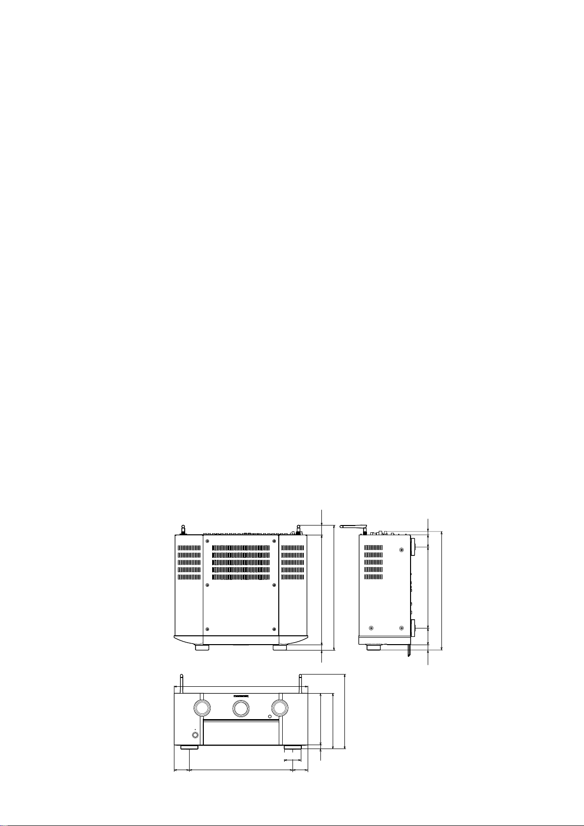
DIMENSION
Unit:mm
Weight:29lb16oz(13.6kg)
32
39 11
267
361
410
17
440
248
171
185
56
50
340
14
50
389
55
17
9
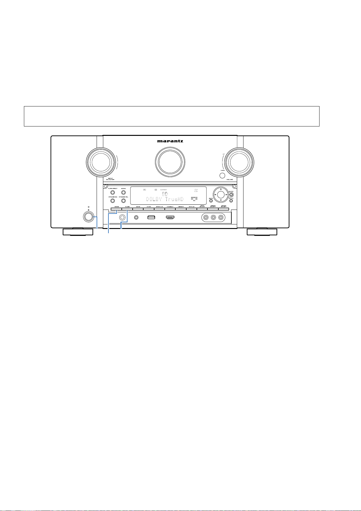
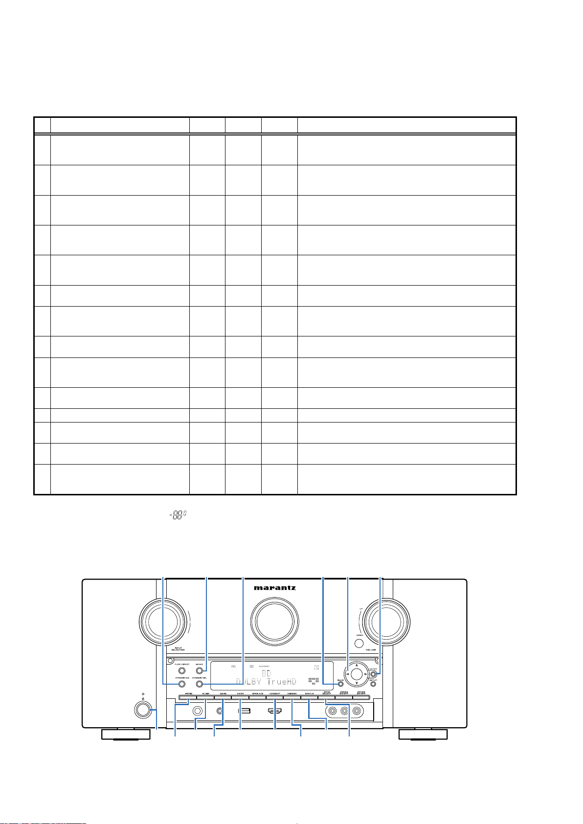
PRECAUTIONS DURING SERVICE
Initializing This Unit
Initialize this unit if you have replaced the microcomputer, one of the parts around the microcomputer, or the digital PCB.
1. Press the power button to turn off the power.
2. Hold down buttons "
3. Release the buttons after conrming that the display ashes in intervals of approximately 1 second.
The unit is initialized.
*
MOVIE
" and "
MUSIC
" at the same time and press the power button to turn on the power.
NOTE:
•Ifthestatusinstep3doesnotoccur,startagainfromstep1.
•Initializingthedevicerestoressettingsconguredbytheusertothefactorysettings.Takenoteofyoursettingsbeforehand
andrecongurethemafterinitialization.
MOVIE
MUSIC
X
Service Jigs
The following jigs (extension cable kit) are used when repairing the PCBs.
Order the jigs from your dealer if necessary.
8U- 110084S : EXTENSION UNIT KIT : 2 Set
(See 72 page)
10
DISASSEMBLY
• Remove each part in the order of the arrows below.
• Reassemble removed parts in the reverse order.
• Read
"Precautions During Work"
• If wire bundles are removed or moved during adjustment or part replacement, reshape the wires after completing the
work. Failure to shape the wires correctly may cause problems such as noise.
before reassembling removed parts.
FRONTPANELASSY
See"DISASSEMBLY"
2.FRONTPANELASSY
and"EXPLODED VIEW"
PCB FRONT
(Ref.No.ofEXPLODEDVIEW:A1)
PCB SOURCE
(Ref.No.ofEXPLODEDVIEW:A2)
PCB VOL
(Ref.No.ofEXPLODEDVIEW:A3)
PCB H/P
(Ref.No.ofEXPLODEDVIEW:A5)
PCB DOOR SW
(Ref.No.ofEXPLODEDVIEW:A7)
PCB FRONT HDMI USB
(Ref.No.ofEXPLODEDVIEW:C4)
PCB BT MODULE
(Ref.No.ofEXPLODEDVIEW:G2)
TOPCOVER
CX870ASSY
See"DISASSEMBLY"
1.CX870ASSY
and"EXPLODED VIEW"
PCB CX870 CONNECT
(Ref.No.ofEXPLODEDVIEW:G1)
CX870 MODULE
(Ref.No.ofEXPLODEDVIEW:73)
HDAMASSY
See"DISASSEMBLY"
3.HDAMASSY
and"EXPLODED VIEW"
PCB HDAM CONNECT
(Ref.No.ofEXPLODEDVIEW:A6)
PCB HDAM XLR-AMP
(Ref.No.ofEXPLODEDVIEW:C1)
SMPSPCB
See"DISASSEMBLY"
4.SMPSPCB
and"EXPLODED VIEW"
PCB SMPS
(Ref.No.ofEXPLODEDVIEW:B6)
POWERTRANS
See"DISASSEMBLY"
5.POWERTRANS
and"EXPLODED VIEW"
POWER TRANS
(Ref.No.ofEXPLODEDVIEW:15)
BACKPANELASSY
See"DISASSEMBLY"
6.BACKPANELASSY
and"EXPLODED VIEW"
PCB PHONO
(Ref.No.ofEXPLODEDVIEW:A4)
PCB XLR OUT
(Ref.No.ofEXPLODEDVIEW:
B1,B2,B3,B4,B5)
PCB XLR IN_TEMOTE IO_232C
(Ref.No.ofEXPLODEDVIEW:C2)
PCB CONNECTR-3
(Ref.No.ofEXPLODEDVIEW:C3)
PCB AUDIO VIDEO
(Ref.No.ofEXPLODEDVIEW:D1)
PCB CONNECT-1
(Ref.No.ofEXPLODEDVIEW:D3)
PCB CONNECT-2
(Ref.No.ofEXPLODEDVIEW:D4)
PCB CONNECT-4
(Ref.No.ofEXPLODEDVIEW:D8)
PCB CONNECT-5
(Ref.No.ofEXPLODEDVIEW:D9)
PCB DAC
(Ref.No.ofEXPLODEDVIEW:E1)
PCB DIGITAL
(Ref.No.ofEXPLODEDVIEW:F)
11
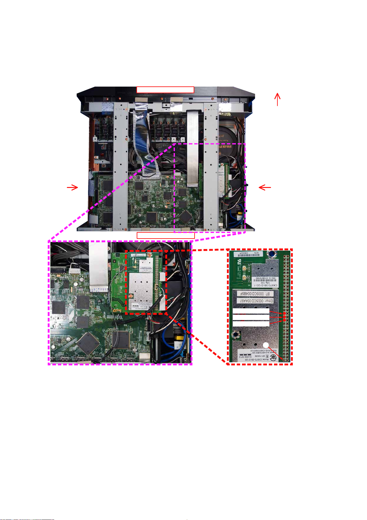
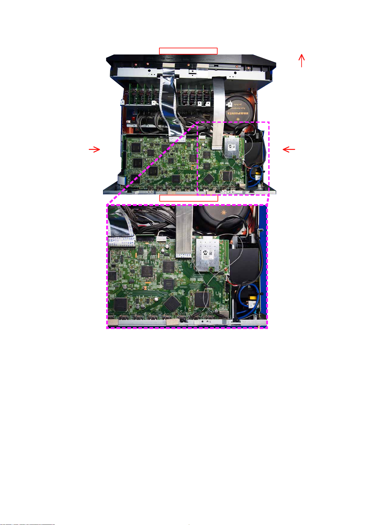
Explanatory Photos for DISASSEMBLY
• The angles from which the photos are taken are shown by "
• See the diagram below about the shooting direction of each photograph.
• Photographs with no shooting direction indicated were taken from the top of the unit.
• The photograph is AV8802U model.
The viewpoint of each photograph for AV8802
(Shooting direction:X)[View from the top] s
↓Shooting direction: B↓
Photo angle: A, B, C, D
D
".
Front side
Shooting
direction: D
Shooting
direction: C
↑Shooting direction: A↑
Black wire 15
White wire 14
Green wire 13
1
12
The viewpoint of each photograph for AV8802A
(Shooting direction:X)[View from the top]
↓Shooting direction: B↓
D
Front side
Shooting
direction: D
Shooting
direction: C
↑Shooting direction: A↑
13
1. CX870 ASSY for CX870 model only
63301020220AS
2
R3424
R3428
R623
C3484
C3485
C3486
R649
C2110
R650
C2114
C2117
R658
R659
C2121
R660
C2124
R661
C626
C627
C2128
C632
R670
R671
C637
C638
C639
R677
R678
C644
L2003
R684
R685
C649
C650
C651
C654
R691
L2011
R692
L2012
R693
C657
R694
C659
C661
C5041
C662
C663
D605
D606
C668
C673
R727
TOP
1
25
TOP
25
N3403
C2061
C2064
C2068
L604
L606
L608
L610
R3415
R3416
2
without FLANGE
Proceeding : TOP COVER L/R/CENTER → CX870 ASSY
(1) Remove the screws. Remove the connector wire. s
CON1
CON2
x2
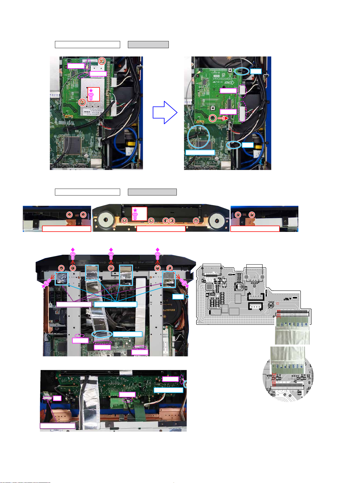
2. FRONT PANEL ASSY
Proceeding : TOP COVER L/R/CENTER → FRONT PANEL ASSY
(1) Remove the screws.
x12
Shooting direction: C Shooting direction: D
View from the bottom
CUT
N903
N901
CUT
STYLE PIN
(2) Cut the wire clamp, then remove the ALUMINUM TAPE, STYLE PIN, FFC and connector wire. Remove the screws.
NewFRONTHDMIUSBPCBONLY
Pleasebecarefulasthereisinsertiondirection
AV8802 ONLY
N5009
ALUMINUM TAPE
STYLE PIN
CUT
K5501
C5503
C5501
U5501
C5502
R5512
C5506
R5503
D5501
R5505
C5507
C5508
R5513
C5509
R5515
R5514
D5502
R5506
R5507
C5505
R5502
R5504
R5501
Q5502
Q5501
R5509
R5510
R5511
R5508
C5504
C5516
C5517
C5518
C5519
C5520
R5559
D5559
C5564
C5559
C5560
C5510
C5511
C5513
C5512
C5514C5515
N5559
D5560
D5561
L5560
L5559
C5561
N5560
N5561
FRONT HDMI USB PCB
N5501
R5516
2
HDMI/USB
25
25
R5517
R5518
R5519
FFC
FFC
DIGITAL PCB
(3) Disassemble the FRONT PANEL ASSY. Remove the STYLE PIN and connector wire.
N1001
STYLE PIN
N1
N5506
8U-210202-4
FRONT
h
1
1
TOP
TOP
AV8802 ONLY
14
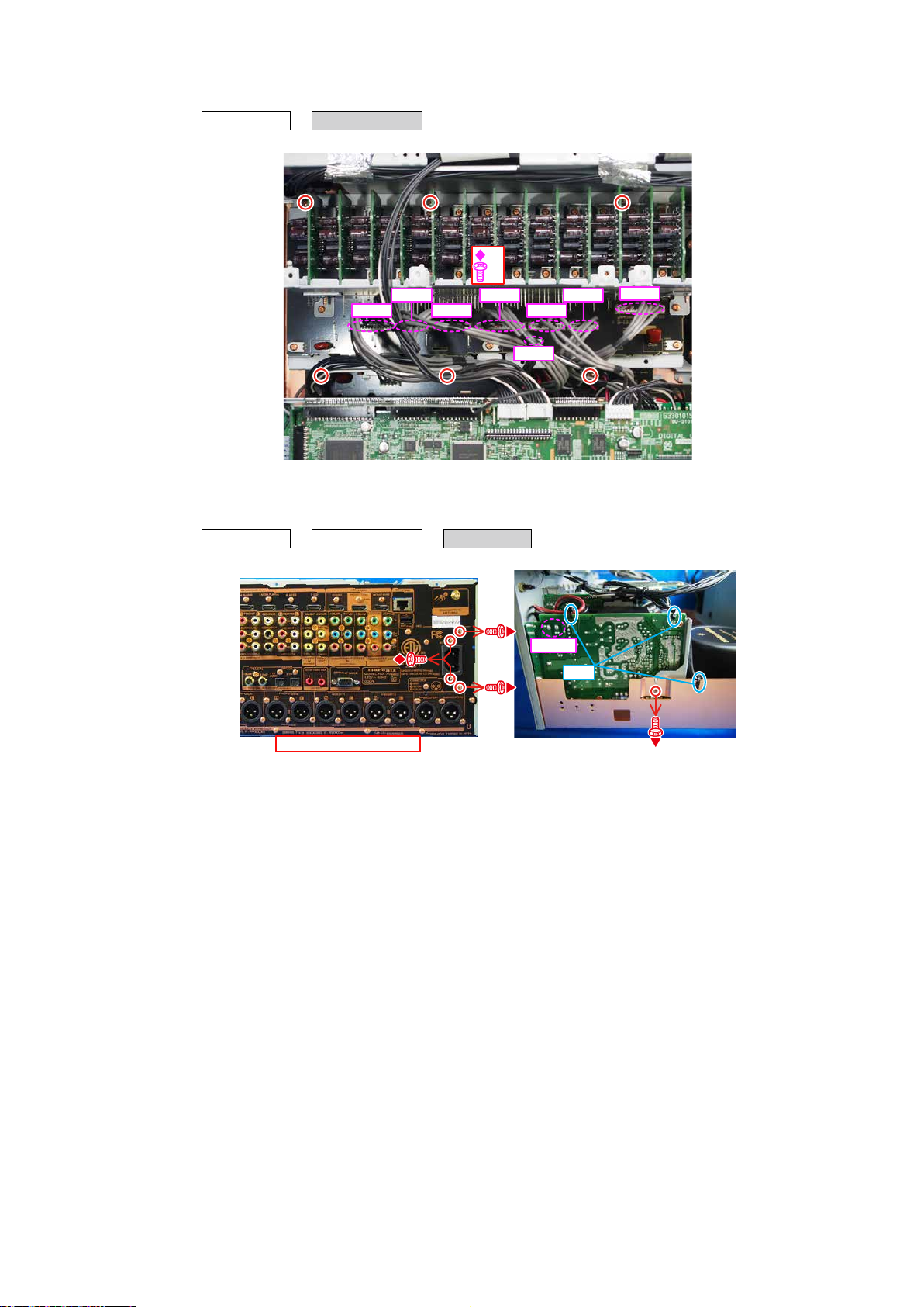
3. HDAM ASSY
Proceeding : TOP COVER → HDAM ASSY
(1) Remove the screws. Remove the connector wire.
x6
N101
N121
N103
N120
N102
N104
N119
4. SMPS ASSY
Proceeding : TOP COVER → CX870 ASSY → SMPS ASSY
(1) Remove the screws. Cut the wire clamp, then remove the connector wire.
N6501
CUT
↑Shooting direction: A↑
Shooting
direction: C
N105
15
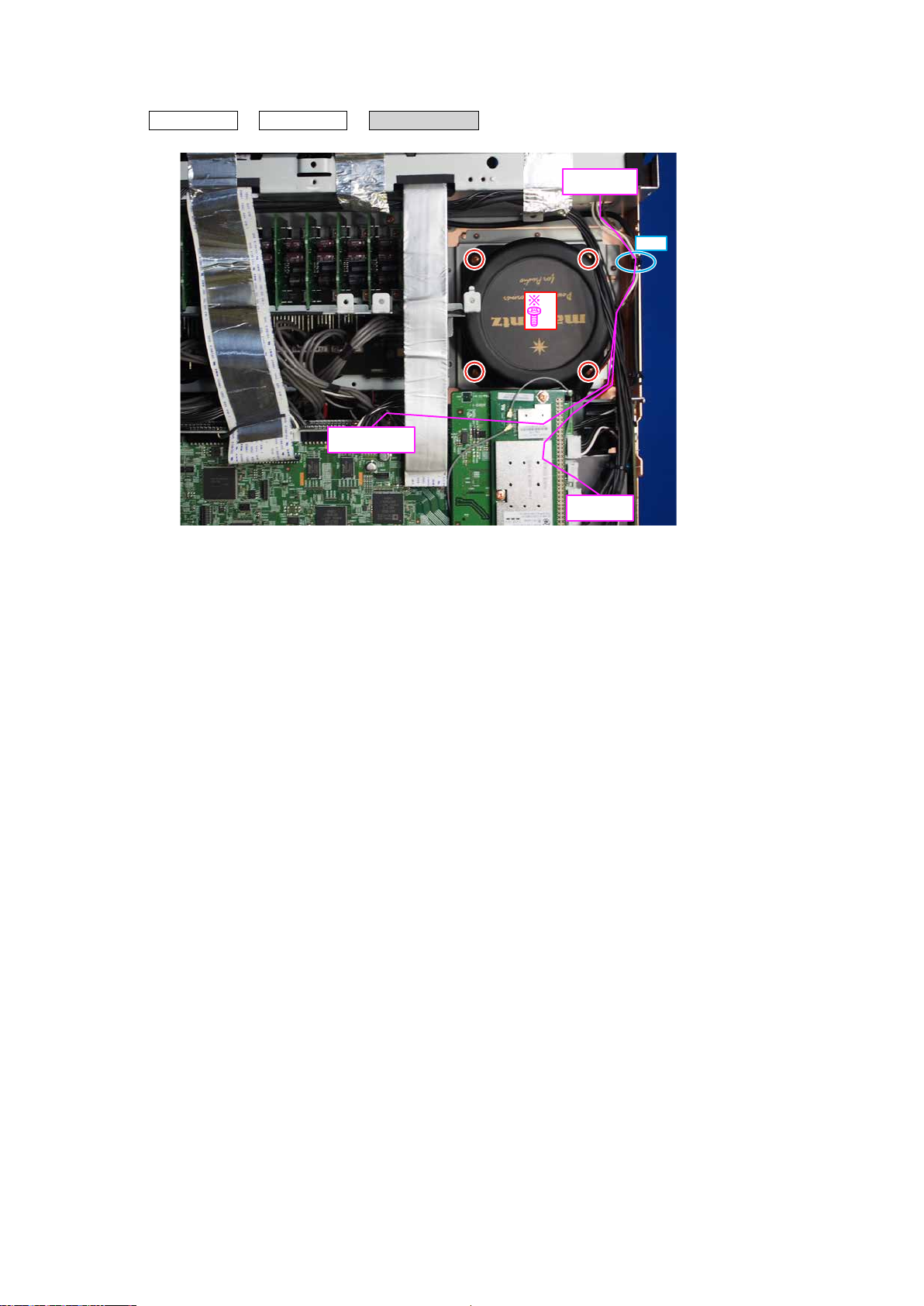
5. POWER TRANS
Proceeding : TOP COVER → SMPS ASSY → POWER TRANS
(1) Remove the screws. Cut the wire clamp, then remove the connector wire.
x4
TO XLR OUT
N5202
TO FRONT
N1001
CUT
TO SMPS
N6501
16
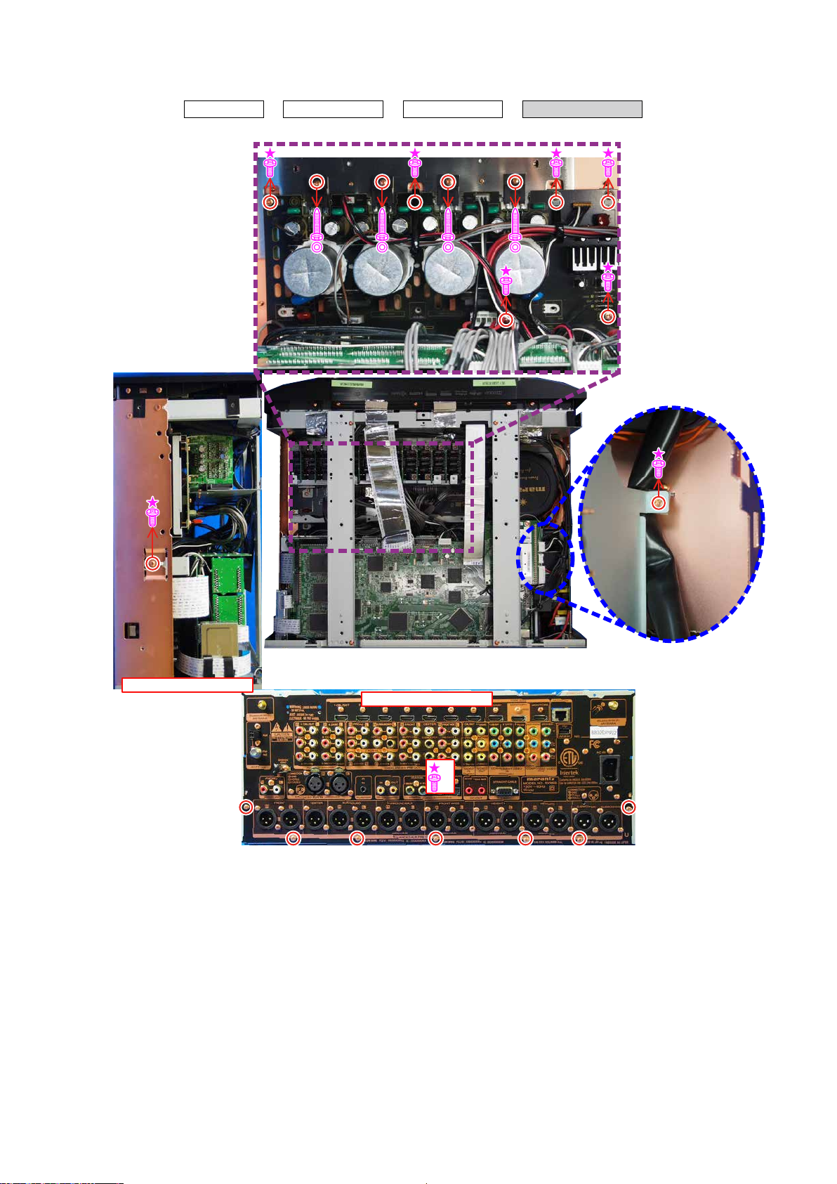
6. BACK PANEL ASSY
Proceeding : TOP COVER → HDAM ASSY → SMPS ASSY → BACK PANEL ASSY
(1) Remove the screws.
Shooting direction: D
Shooting direction: A
x7
17
SPECIAL MODE
Special Mode Conguration Buttons
No.1-10,13: Holddownbuttons"A","B"and"C"atthesametimeandpressthepowerbuttontoturnonthepower.
b
No.11,12: Holddownbuttons"A"and"B"foratleast3secondswhilethepowerison.
b
No.14: Pressthe"A"and"B"buttonssimultaneouslywhileinsertingtheACplugtoturnthepoweron.
b
No. Mode Button A Button B Button C Contents
VersionDisplayMode
1
(u-COM/DSPErrorDisplay)
UserInitializationMode
(SettingsfortheInstallerSetuparenot
2
initialized.)
FactoryInitializationMode
(Initializationincludessettingsforthe
3
InstallerSetup.)
PANEL/REMOTELOCKSelectionMode BACK ENTER -
4
ChecktheVideo/Audiopass
5
Mode
232CStandbyClearMode ↑ ↑ -
6
OperationInfoMode ↑ ↑ -
7
TUNERSTEPMode
8
(Nmodelonly)
InstallerSetupMode
9
AdditionalSourceMode SLEEP A-DSX -
10
CX870/CY920RebootMode BACK ENTER - RestartsCX870/CY920.(See71page)
11
CX870/CY920InitializationMode M-DAX
12
USBUpdateMode
13
ForcedUSBAllDeviceWriteMode
14
DIMMER STATUS -
GAME A-DSX -
MOVIE MUSIC -
ZONE
SELECT
↑ ↑ -
CURSOR
0
HDMI
OUT
HDMI
OUT
BACK -
BACK -
DYNAMIC
EQ
STATUS
STATUS -
DisplaystheversionofrmwaresuchasthemainrmwareorDSP,
etc.Errorsthathaveoccurredaredisplayed.
(See19page)
Initializesbackupdata.
(SettingsfortheInstallerSetuparenotinitialized.)
Initializesbackupdata.
(InitializationincludessettingsfortheInstallerSetup.)
StartthisunitinthePANEL/REMOTELOCKselectionmodesothat
PANELLOCKandRemoteLockcanbeselectedasONorOFF.
(See23page)
Thisisaspecialmodeforserviceconrmationusedduringrepair
worktosimplifytheconrmationworkfortheAudiochannel/video
channel.(See24page)
Switchesfrom232Cstandbymodetonormalstandbymode.
(See69page)
Displaysthetotaloperatingtimeoftheset,numberoftimes
thepowerwasswitchedon,andnumberofoccurrencesofeach
protection.(See69page)
EnablesreceptionSTEPoftheANALOGTUNERtobechanged.
(See70page)
AccesstheRemoteMaintenancemodeviatheinternet.InstallerSetup
isdisplayedonSetupmenu/Network.
RefertoAVR_RemoteMaintenance_.pdfofSDI.
b
AddsAUX3-7asaSource.
(See70page)
EnterthismodeonlyafterreplacingFlashforCX870/CY920and
rewritingthermware.(See71page)
SwitchesthisunittoUSBUpdatemode.
(See74page)
Modeusedwhenthisunitcannotberecovered.
ForciblyswitchesthisunittoUSBupdatemode.
(See77page)
NOTE :
When the volume indicator displays " ", the set has entered a special mode for developers. In this case, RS-232C communication
cannot be used.
To cancel this special mode, press and hold the "
returns to the normal display, RS-232C communication can be used.
DYNAMIC
EQ M-DAX
X
MOVIE
MUSIC
DIMMER
GAME
"and "
DYNAMIC
VOL
A-DSX
STATUS
HDMI
OUT
" buttons for 3 seconds and longer. When the volume indicator
BACK ENTER
STATUS
DIMMER
0
ZONE
SELECT
18
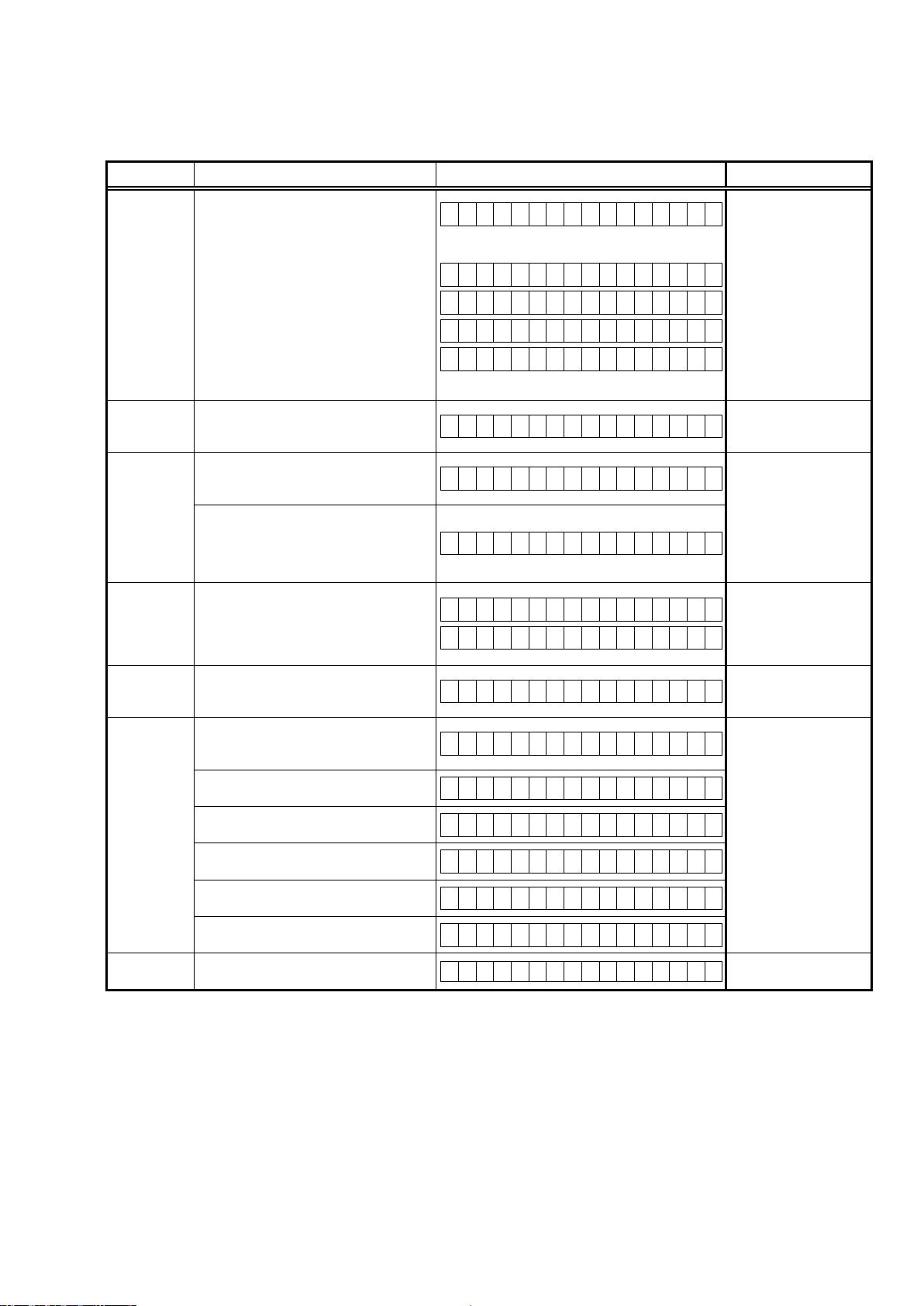
1. Version Display Mode
1.1. Actions
Version information is displayed when the device is started in this mode.
1.2. Starting up
Hold down buttons "
Press the "
A version list is also displayed on GUI while the version appears on the display.
b
STATUS
DIMMER
" button after this to show the information in section 1.3 on the display.
1.3. Display Order
Error information(See "
→ w Firmware Package Version → e Main µ-com, Main 1st Boot Loader Version
→ r Sub µ-com, Sub 1st Boot Loader Version → t DSP1/2/3/4 ROM → y Audio, Video PLD → u GUI SFLASH
→ i Ethernet 1st Boot Loader, Hardware ID → o Ethernet 2nd Boot Loader, Rhapsody Flag → Q0 Ethernet IMAGE
→ Q1 Ethernet MAC ADDRESS information → Q2 BT MAC ADDRESS information → Q3 HD Radio(U only)
→ Q4 MultEQ Pro APP (Displayed when Audyssey Pro is complete) → Q5 MultEQ Pro ICL (Displayed when Audyssey Pro
is complete)
Model destination information, Serial Number :
q
FLD L1
FLD L1
FLD L2
A V 8 8 0 2 Z *
A V 8 8 0 2 A Z
S / N . * * * * * * * * * *
" and "
STATUS
1.4. Error display
" at the same time and press the power button to turn on the power.
") → q Model destination information, Serial Number
CaseofCX870:Display"*"attheend
Z
:Region(U,N,F)
Z
:Region(U,N,F)
AV8802AONLY
d
Firmware Package Version :
w
FLD
e
FLD
r
FLD L1
FLD L1
FLD L2
t
FLD
DSP 3/4 ROM :
FLD
L1
L2
Main µ-com, Main 1st Boot Loader Version :
L1
L2
Sub µ-com, Sub 1st Boot Loader Version : Model code
DSP 1/2 ROM :
L1
L2
L1
L2
F i r m . P a c k a g e
V e r . : * * * *
M a i n : * * . * * *
M a i n F B L : * * . * *
S u b : 2 9 2 0 * * * *
S u b : 4 5 2 0 * * * *
S u b F B L : * * . * *
D S P 1 : * * . * *
D S P 2 : * * . * *
D S P 3 : * * . * *
D S P 4 : * * . * *
CaseofCX870:Display"*"attheend
AV8802ONLY
AV8802AONLY
d
d
Audio, Video PLD :
y
FLD
L1
L2
A u d i o P L D : * * . * *
V i d e o P L D : * * . * *
19
GUI SFLASH :
u
FLD
i
FLD
o
FLD
Q0
FLD
Q1
FLD
L1
L2
Ethernet 1st Boot Loader, Hardware ID :
L1
L2
Ethernet 2nd Boot Loader, Rhapsody Flag :
L1
L2
Ethernet IMAGE :
L1
L2
Ethernet MAC ADDRESS information :
L1
L2
G U I : 2 9 2 Z * * * *
Z
: Region code(U / N / F = 1, K = 5)
E t h e r n e t F B L
* * * * * * - A A
AA
: Hardware ID
E t h e r n e t S B L
* * * * * * * * * * * * * - B B
E t h e r n e t I M G
* * * * * * * * * * * * *
* N E T M A C A d d r e s s
* * * * * * * - * * * * *
BT MAC ADDRESS information :
Q2
L1
FLD
HD Radio :
Q3
FLD
S
: Software Conguration, R : Release Type, V : Base Version No., B : Build No.
MultEQ Pro APP :
Q4
FLD
MultEQ Pro ICL :
Q5
FLD
* B T M A C A d d r e s s
L2
L1
L2
L1
L2
L1
L2
* * * * * * - * * * * * S
* H D : S S S S S S S S -
R V V V V . B B B
* M u l t E Q P r o A P P
* * . * * . * * . * * * *
* M u l t E Q P r o I C L
* * . * * . * * . * * * *
20
1.4. Error display
If multiple errors occur, only one item is displayed.
The priority order is w,e,r,t,y,u,q.
Condition States Display TROUBLE SHOOTING
Themodelname,brandnameandregion
informationwritteninthermwareare
comparedtotheregionsettingsinthe
PCB.Thiserrorisdisplayediftheinforma-
q
FirmCheck
NG
w
SUBμ -COMNGThereisnotareplyfromSUBμ-COM.
e
IPSCALERNG
r
GUISerial
FlashNG
t
DIRNG
y
DSP*NG
(*:1/2/3/4)
u
EEPROMNG
tiondoesnotmatch.
" ▲ "isdisplayedastherstcharacterif
thermwareisnotcorrect(seerightsectionoftable).
AnerroroccursinLoopbackTestofthe
DDRmemorytoperformatinitialsetting
ofi/pScaler(ADV8003).
Ininitialsettingofi/pScaler(ADV8003),
thereisnotthereplyoftheLoopbackTest
resultoftheDDRmemory.
WhenitisdifferentfromVersionofthe
MainCPUwhichVersionofGUISerial
Flashsupports.(ADV8003)
" ▼ "isdisplayedastherstcharacterof
theGUIrmwareversion.
ThiserrorisdisplayedifthereisnoresponsefromtheDIR.
TheDSP*FLAG0portdoesnotenter"Hi"
statusevenafterexecutingaDSPreset
duringaDSPcodeboot.
TheDSP*FLAG0portdoesnotenter"Hi"
statusbeforeissuingaDSPcommand.
ACK="Hi"doesnotoccurduringDSP*
datareading,evenwhenWRITE="Lo".
ACK="Lo"doesnotoccurduringDSP*
datareading,evenwhenREQ="Lo".
ACK="Hi"doesnotoccurduringDSP*
datawriting,evenwhenWRITE="Hi".
ACK="Lo"doesnotoccurduringDSP*
datawriting,evenwhenREQ="Lo".
Anerroroccurredinachecksumofthe
EEPROM(***isablockaddressnumber).
F I R M E R R O R
–
M a i n : * * . * *
–
D S P 1 : * * . * *
–
A u d i o P L D : * * . * *
–
G U I : * * * * * * * *
S U B E R R O R 0 1
I P S C A L E R E R R 0 1
I P S C A L E R E R R 0 2
G U I V E R . E R R O R
•
G U I : * * * * * * * *
D I R E R R O R 0 1
D S P * E R R O R 0 1
D S P * E R R O R 0 2
D S P * E R R O R 0 3
D S P * E R R O R 0 4
D S P * E R R O R 0 5
D S P * E R R O R 0 6
E 2 P R O M E R R * * *
•Checktheresistorfor
settingregion(R5003,
R5004,R5006,R5007,
R5013,R5014DIGITAL
PCB).
•Writethermwarefor
thecorrectregion.
•ChecktheSUB(U2101)
andsurroundingcircuits.
• Check the circuits
around the IP SCALER
(U2800, DIGITAL PCB)
and DDR2 (U3000/
U3001).
If there appear to be
no problems, U2800 or
U3000/U3001 is faulty.
•Checkthermwareversion.
•ChecktheDIR(U1000,
DIGITALPCB)andsurroundingcircuits.
•ChecktheDSP(U101,
U201,U301,U401,DIGITALPCB)andsurroundingcircuits.
21
1.5. Version Display in the Setup Menu
Follow the steps below to display the rmware information.
(1) Press the "
(2) Select "
SETUP
" button on the remote control.
General - Information - Firmware
".
The version information is displayed as a 14-digit number as shown in the screenshot below.
General/Firmware
Version
Displays system information
XXXX-XXXX-XXXX
GUI Image
This 14-digit number comprises part of the version number of each device and module.
These version numbers correspond to the 14-digit number as shown below.
The 2nd digit from the right for Main
The 1th digit from the right for Main
The 2nd digit from the right for Sub
The 1st digit from the right for Sub
Main
Sub
DSP1
DSP2
DSP3
DSP4
A.PLD
V.PLD
GUI
E.FBL
E.SBL
E.IMG
X
8X 3 8- 3 8 21
X X X 0 0 2 8
X X X
X X X
X X X
X X X
X X X
X X X
2
3
4
5
1
7
X X X X 0 0 1 6
The 1st digit from the right for DSP1
The 1st digit from the right for DSP2
The 1st digit from the right for DSP3
The 1st digit from the right for DSP4
The 1st digit from the right for A.PLD
The 1st digit from the right for V.PLD
The 1st digit from the right for GUI
X X X X X X
XB X X X X X X X X X X X
XI X X X X X X X 0 0 3 7
Info display 2 3 4 - 6 7 7 3 - 0 5
The 1st digit from the right for IMG
The 2nd digit from the right for IMG
The rmware version numbers and this 14-digit version information are written in the Service Information.
b
22
2. PANEL / REMOTE LOCK Selection Mode
2.1. Actions
Turn the PANEL LOCK and REMOTE LOCK modes on and off.
2.2. Starting up
Hold down buttons "
Select the mode using the button "
BACK
2.3. Displaying and Selecting Each Mode
The information shown on the display changes each time the button "
Press the button "
The On/Off setting for each mode is shown by an asterisk "*".
q
FLD
The buttons on the unit and the master volume knob cannot be operated.
w
FLD
The buttons on the unit cannot be operated.
e
FLD
The PANEL LOCK mode is turned off.
r
FLD
The device cannot be operated by the remote control.
t
FLD
The REMOTE LOCK mode is turned off.
L1
L2
L1
L2
L1
L2
L1
L2
L1
L2
ENTER
" to set the currently displayed mode and restart the device.
– F P / V O L L O C K * O n
F P L O C K O n
F P / V O L L O C K * O n
– F P L O C K O n
F P L O C K * O n
– F P L O C K O f f
F P L O C K O f f
– R C L O C K O n
R C L O C K O n
– R C L O C K O f f
" and "
ENTER
" at the same time and press the power button to turn on the power.
CURSOR f/d"
", and press the button "
ENTER
CURSOR f/
" to commit the selection.
" is pressed.
d
23
3. Selection Modes for Service-related Operations
3.1. Actions
Select diagnostic mode (service path check mode), 232C standby clear mode, Operation Info mode or TUNER STEP
mode(U and N model only).
3.2. Starting up
Hold down buttons "
Select the mode using the button "
ZONE SELECT
CURSOR f/
3.3. Displaying and Selecting Each Mode
The information shown on the display changes each time the button "
Press the button "
q
FLD
Service Path Check Mode:
The Video and Audio paths can be checked.
This function is convenient for conrming problem paths in the product and executing a path
w
FLD
Switches from 232C standby mode to normal standby mode.
L1
L2
L1
L2
ENTER
" to set the currently displayed mode and restart the device.
– 1 . S E R V I C E C H E C K
3 . R S 2 3 2 C R E S E T
check after repair.
1 . S E R V I C E C H E C K
– 3 . R S 2 3 2 C R E S E T
" and "
BACK
" at the same time and press the power button to turn on the power.
", and press the button "
d
ENTER
CURSOR f/
" to commit the selection.
" is pressed.
d
e
FLD
Operation Info for the unit can be checked.
r
FLD
Enables reception STEP of the ANALOG TUNER to be changed.
L1
L2
L1
L2
3 . R S 2 3 2 C R E S E T
– 4 . O P I N F O
4 . O P I N F O
– 5 . T U N E R F R Q S E T
3.4. Canceling the mode
Press the power button to turn off the power.
24
3.4. DIAGNOSTIC MODE (Service Path Check Mode)
3.4.1. Actions
This function is convenient for conrming problem paths in the product and executing a path check after repair.
The Video and Audio paths can be checked.
The backup data is not rewritten.
3.4.2. Starting up
Hold down buttons "
Select "
The "
1. SERVICE CHECK
TUNED
STERO
", "
ZONE SELECT
" and press the "
RDS
" and "
BACK
" and "
" at the same time and press the power button to turn on the power.
ENTER
" button to start the diagnostic mode.
" segments are lit in this mode.
3.4.3. Canceling diagnostic mode
Press the power button to turn off the power.
3.4.4. Selecting items
Press q button to switch between video items and audio items.
Press button w or e to select the previous or next item.
The unit Remote control unit
Actions
Button DIMMER CURSOR
q w e q w e
Audio ⇔ Video PREVIOUS NEXT Audio ⇔ Video PREVIOUS NEXT
0
CURSOR
1
SLEEP CURSOR
0
3.4.5. Audio system conrmation items
g. XX: See the block diagram of the g.XXth.
CURSOR
1
Paths conrmation item Display Settings Contents of conrmation Remarks
Analog
(MAIN ZONE)
1
Digital
(MAIN ZONE)
2
Digital (signal) Path
(ZONE2)
3
Digital (signal) Path
(ZONE3)
4
HDMI
(MAIN ZONE)
5
g.01
g.02a
g.02b
g.03a
g.03b
g.03c
g.04a
g.04b
g.05a
g.05b
g.05c
A 0 1 : A N A L O G P A S S
A 0 2 : D I G I T A L
A 0 3 : D I G I T A L - Z 2
A 0 4 : D I G I T A L - Z 3
A 0 5 : H D M I
Input Source : CBL/SAT
Input Mode : Analog(xed)
Sound mode : Direct
Vol. : 60.0(-20.0dB)
Amp assign : 11.1ch
ZONE2 : OFF
ZONE3 : OFF
Input Source : CBL/SAT
Input Mode : Digital(xed)
Sound mode : Multi Ch Stereo
Vol. : 60.0(-20.0dB)
Amp assign : 11.1ch
Speaker Select : Floor
Speaker Cong : All Speaker=Small/Subwoofer=2spkrs
ZONE2 : OFF
ZONE3 : OFF
Input Source : Online Music
Input Mode : Auto
Sound mode : Stereo
Amp assign : 11.1ch
ZONE2 : ON
ZONE2 Source : Source
Z2 Vol. : 60.0(-20.0dB)
ZONE3 : OFF
Input Source : Online Music
Input Mode : Auto
Sound mode : Stereo
Amp assign : 11.1ch
ZONE2 : OFF
ZONE3 : ON
ZONE3 Source : Source
Z3 Vol. : 60.0(-20.0dB)
Input Source : CBL/SAT
Input Mode : HDMI(xed)
Sound mode : Stereo
Vol. : 60.0(-20.0dB)
Amp assign : 11.1ch
ZONE2 : OFF
ZONE3 : OFF
・Analog input ⇒ RCA output (Front L/R)
・Analog input ⇒ XLR output (Front L/R)
(b The input source can be switched to any source except CBL/SAT.)
・Digital input ⇒ RCA output (Front L/R, Center, Surround L/R, Surround Back L/R, Subwoofer)
・Digital input ⇒ XLR output (Front L/R, Center, Surround L/R, Surround Back L/R, Subwoofer)
(b The input source can be switched to any source except CBL/SAT.)
・Digital(PCM) input ⇒ ZONE2 RCA output (ZONE2 L/R)
(b The input source can be switched to any source except Online Music.)
・Digital(PCM) input ⇒ ZONE3 RCA output (ZONE3 L/R)
(b The input source can be switched to any source except Online Music.)
・HDMI Input ⇒ RCA output (Front L/R)
・HDMI Input ⇒ XLR output (Front L/R)
(b The input source can be switched to any source except CBL/SAT.)
25
Paths conrmation item Display Settings Contents of conrmation Remarks
A/D
(MAIN ZONE)
6
Amp Assign
(ZONE2)
7
Amp Assign
(ZONE3)
8
Amp Assign
(BiAMP-Surround Back)
9
Amp Assign
(BiAMP-Front Wide)
10
Amp Assign
(BiAMP-Height1)
11
Front Height
12
g.06a
g.06b
g.07
g.08
g.09
g.10a
g.10b
g.11a
g.11b
g.12a
g.12b
A 0 6 : A D
A 0 7 : A S S I G N - Z 2
A 0 8 : A S S I G N - Z 3
A 1 1 : B i A m p - S B
A 1 2 : B i A m p - S W
A 1 3 : B i A m p - H 1
A 1 4 : F R O N T H E I G H T
Input Source : CBL/SAT
Input Mode : Analog(xed)
Sound mode : Multi Ch Stereo
Vol. : 60.0(-20.0dB)
Amp assign : 11.1ch
Height Speakers=2 Height Speakers
Height Layout=Front Height
Speaker Select : Floor
Speaker Cong : All Speaker=Small/Subwoofer=2spkrs
ZONE2 : OFF
ZONE3 : OFF
Input Source : CBL/SAT
Input Mode : Auto
Sound mode : Stereo
Amp assign : 11.1ch
ZONE2 : ON
Z2 Source : Source
Z2 Vol : 60(-20dB)
ZONE3 : OFF
Input Source : CBL/SAT
Input Mode : Auto
Sound mode : Stereo
Amp assign : 11.1ch
ZONE2 : OFF
ZONE3 : ON
ZONE3 Source : Source
Z3 Vol. : 60.0(-20.0dB)
Input Source : CBL/SAT
Input Mode : Auto
Sound mode : Stereo
Vol. : 60.0 (-20.0dB)
Amp assign : 9.1ch(Bi-Amp)
Speaker for Bi-Amp : SURROUND BACK
MAIN ZONE ON
ZONE2 OFF
ZONE3 OFF
Input Source : CBL/SAT
Input Mode : Auto
Sound mode : Stereo
Vol. : 60.0 (-20.0dB)
Amp assign : 9.1ch (Bi-Amp)
Speaker for Bi-Amp : FRONT WIDE
MAIN ZONE ON
ZONE2 OFF
ZONE3 OFF
Input Source : CBL/SAT
Input Mode : Auto
Sound mode : Stereo
Vol. : 60.0 (-20.0dB)
Amp assign : 9.1ch (Bi-Amp)
Speaker for Bi-Amp : HEIGHT1
MAIN ZONE ON
ZONE2 OFF
ZONE3 OFF
Input Source : CBL/SAT
Input Mode : Auto
Sound mode : Multi Ch Stereo
Vol. : 60.0(-20.0dB)
Amp assign : 11.1ch
Height Speakers : 4Height Speakers
Height Layout : Top Front & Top Rear
Speaker Cong : Front Wide=None
Speaker Select : Floor & Height
MAIN ZONE ON
ZONE2 : OFF
ZONE3 : OFF
・Analog input ⇒ RCA output (Front L/R, Center, Surround L/R, Surround Back L/R, Front Wide L/R, Subwoofer)
・ Analog input ⇒ XLR output, SW(20Hz) (Front L/R, Center, Surround L/R, Surround Back L/R, Front Wide L/R, Subwoof-
er)
(b The input source can be switched to any source except CBL/SAT.)
(b Volume -20dB is the value when Relative settings are used. The value is 60 when Absolute settings are used)
・Analog input ⇒ ZONE 2 RCA output (ZONE2 L/R)
(b The input source can be switched to any source except CBL/SAT.)
(b Volume -20dB is the value when Relative settings are used. The value is 60 when Absolute settings are used)
・Analog input ⇒ ZONE 3 RCA output (ZONE3 L/R)
(b The input source can be switched to any source except CBL/SAT.)
(b Volume -20dB is the value when Relative settings are used. The value is 60 when Absolute settings are used)
・Analog input ⇒ RCA output (Front L/R, Surround Back L/R → Front)
・Analog input ⇒ XLR output (Front L/R, Surround Back L/R → Front)
(b The input source can be switched to any source except CBL/SAT.)
(b Volume -20dB is the value when Relative settings are used. The value is 60 when Absolute settings are used)
・Analog input ⇒ RCA output (Front L/R, Front Wide L/R → Front)
・Analog input ⇒ XLR output (Front L/R, Front Wide L/R → Front)
(b The input source can be switched to any source except CBL/SAT.)
(b Volume -20dB is the value when Relative settings are used. The value is 60 when Absolute settings are used)
・Analog input ⇒ RCA output (Front L/R, Height1 L/R → Front)
・Analog input ⇒ XLR output (Front L/R, Height1 L/R → Front)
(b The input source can be switched to any source except CBL/SAT.)
(b Volume -20dB is the value when Relative settings are used. The value is 60 when Absolute settings are used)
・Analog input ⇒ RCA output (Height 1 L/R → Top Front, Height 2 L/R → Top Rear)
・Analog input ⇒ XLR output (Height 1 L/R → Top Front, Height 2 L/R → Top Rear)
(b The input source can be switched to any source except CBL/SAT.)
(b Volume -20dB is the value when Relative settings are used. The value is 60 when Absolute settings are used)
26
Paths conrmation item Display Settings Contents of conrmation Remarks
Front Wide
13
7.1CH IN
14
Back DAC>>Height2
15
Height1 DAC>>Height2
16
g.13a
g.13b
g.14
g.15a
g.15b
g.16a
g.16b
A 1 5 : F R O N T W I D E
A 1 9 : 7 . 1 C H I N
A 2 0 : S B - H E I G H T 2
A 2 1 : H 1 - H E I G H T 2
Input Source : CBL/SAT
Input Mode : Auto
Sound mode : Multi Ch Stereo
Vol. : 60.0(-20.0dB)
Amp assign : 11.1ch
Height Speakers : 4 Height Speakers
Height Layout : Front Height & Top Middle
Speaker Cong: S.Back=None
Speaker Select : Floor
MAIN ZONE ON
ZONE2 : OFF
ZONE3 : OFF
Input Source : CBL/SAT
Input Mode : 7.1CH IN
Vol. : 60.0(-20.0dB)
Amp assign : 11.1ch
Speaker Cong : All Speaker=Small/Subwoofer=2spkrs
Speaker Select : Front, Center, Surround, S.Back, Subwoofer
MAIN ZONE ON
ZONE2 : OFF
ZONE3 : OFF
Input Source : CBL/SAT
Input Mode : Auto
Sound mode : Multi ch Stereo
Vol. : 60.0 (-20.0dB)
Amp assign : 11.1ch
Height Speakers : 4Height Speakers
Height Layout : Top Front & Top Rear
Speaker Conog : Surround Back=None
Speaker Select : Floor & Height
MAIN ZONE ON
ZONE2 OFF
ZONE3 OFF
nput Source : CBL/SAT
Input Mode : Auto
Sound Mode : Multi ch Stereo
Vol. : 60.0 (-20.0dB)
Amp assign : 11.1ch
Height Speakers : 4 Height Speakers
Height Layout : Top Front & Top Rear
Speaker Conog : All Small
Speaker Select : Front
Special conguration :
b
Height1 Path → Fixed the Height1 RCA/XLR of Relay in Off
Height1 Path → Fixed the Height2 RCA/XLR of Relay in On
Back Path → Fixed the Height2 RCA/XLR of Relay in On
Back Path → Fixed the Height2 RCA/XLR of Relay in Off
Wide Path → Fixed the Wide RCA/XLR of Relay in On
Wide Path → Fixed the Height2 RCA/XLR of Relay in Off
MAIN ZONE ON
ZONE2 OFF
ZONE3 OFF
・Analog input ⇒ RCA output (Front Wide L/R)
・Analog input ⇒ XLR output (Front Wide L/R)
(b The input source can be switched to any source except CBL/SAT.)
(b Volume -20dB is the value when Relative settings are used. The value is 60 when Absolute settings are used)
・7.1CH IN input ⇒ RCA output (Front L/R, Center, Surround L/R, S.Back L/R, Subwoofer)
・7.1CH IN input ⇒ XLR output (Front L/R, Center, Surround L/R, S. Back L/R, Subwoofer)
(b The input source can be switched to any source except CBL/SAT.)
・Analog 入力 ⇒ RCA 出力 (Height2 L/R → Top Rear)
・Analog 入力 ⇒ XLR 出力 (Height2 L/R → Top Rear)
(b The input source can be switched to any source except CBL/SAT.)
(b Volume -20dB is the value when Relative settings are used. The value is 60 when Absolute settings are used)
・Analog input ⇒ RCA 出力 ( Top Rear L/R)
・Analog input ⇒ XLR 出力 ( Top Rear L/R)
(b The input source can be switched to any source except CBL/SAT.)
(b Volume -20dB is the value when Relative settings are used. The value is 60 when Absolute settings are used)
Attention : For paths conrmation, in this mode, audio output of Height1 I will be output from the RCA/XLR of Height2.
(No sound is output from the Height1 of RCA / XLR. Sound of Height2 is not output from any terminal.)
27
3.4.6. Video system conrmation items
g. XX: See the block diagram of the g.XXth.
Paths conrmation item Display Settings Contents of conrmation Remarks
Analog Video
1
Video Convert
(Analog or HDMI ⇒ HDMI)
2
HDMI pass
(MAIN ZONE)
3
HDMI CEC
4
HDMI Audio
(Audio : AVR)
5
HDMI Audio
(Audio : TV)
6
GUI
7
HDMI
(ZONE2)
8
g.17
g.18
g.19
g.20
g.21a
g.21b
g.21c
g.22a
g.22b
g.23
g.24
V 0 1 : V I D E O P A S S
V 0 2 : V . C O N V E R T
V 0 3 : H D M I P A S S
V 0 4 : H D M I C E C
V 0 5 : H . A U D I O - A V R
V 0 6 : H . A U D I O - T V
V 0 7 : G U I M E N U O N
V 0 8 : Z O N E 2 H D M I
Input Source : CBL/SAT
Video Convert(IP Scaler) : OFF, All sources
MAIN ZONE : ON
ZONE2 : ON
ZONE3 : OFF
Input Source : CBL/SAT
Video Convert(IP Scaler) : ON, All sources
IP Scaler : "Analog & HDMI", All sources
Resolution : "Auto", All sources
MAIN ZONE : ON
ZONE2 : OFF
ZONE3 : OFF
Input Source : CBL/SAT
Source of Video Convert(IP Scaler) : OFF, All sources
MAIN ZONE : ON
ZONE2 : OFF
ZONE3 : OFF
Input Source : CBL/SAT
HDMI Control : ON
Control Monitor : Monitor1 ( Checking the HDMI Monitor Out1)
MAIN ZONE : ON
ZONE2 : OFF
ZONE3 : OFF
Input Source : CBL/SAT
HDMI Control : OFF
HDMI Audio : AVR ( if checking the audio output from AVR )
Input Source : CBL/SAT
HDMI Control : OFF
HDMI Audio : TV ( if checking the audio output from TV )
Input Source : CBL/SAT
Video Convert(IP Scaler) : ON, All sources
IP Scaler : "Analog & HDMI", All sources
Resolution : "AUTO", All sources
Setup Menu : ON
MAIN ZONE : ON
ZONE2 : OFF
ZONE3 : OFF
Input Source : CBL/SAT
ZONE2 Source : Source
MAIN ZONE : ON
ZONE2 : ON
ZONE3 : OFF
・Component input ⇒ Component output
(b The input source can be switched to any source except CBL/SAT.)
・CVBS input ⇒ IP Scaler ⇒ HDMI output.
・Component input ⇒ IP Scaler ⇒ HDMI output.
・HDMI input ⇒ IP Scaler ⇒ HDMI output.
・ETHERNET input ⇒ IP Scaler ⇒ HDMI output.
(b The input source can be switched to any source except CBL/SAT.)
・HDMI input ⇒ HDMI output(MAIN ZONE)
(b The input source can be switched to any source except CBL/SAT.)
・ When the power supply of a TV is put in the standby mode, make sure that the power supply of this unit is also put
in the standby mode.
・The ARC path can also be checked (check this using the TV input source).
(b The input source can be switched to any source except CBL/SAT.)
・HDMI input(PCM, DolbyDigital, DTS) ⇒ RCA/XLR output.
・HDMI input(HD audio) ⇒ RCA/XLR output.
(b The input source can be switched to any source except CBL/SAT.)
・HDMI input(PCM, DolbyDigital DTS) ⇒ HDMI output (audio output from connected TV)
(b The input source can be switched to any source except CBL/SAT.)
・GUI display ⇒ HDMI output.
(b The input source can be switched to any source except CBL/SAT.)
・HDMI input ⇒ HDMI output (ZONE2)
(b The input source can be switched to any source except CBL/SAT.)
28
DIAGNOSTIC PATH DIAGRAM
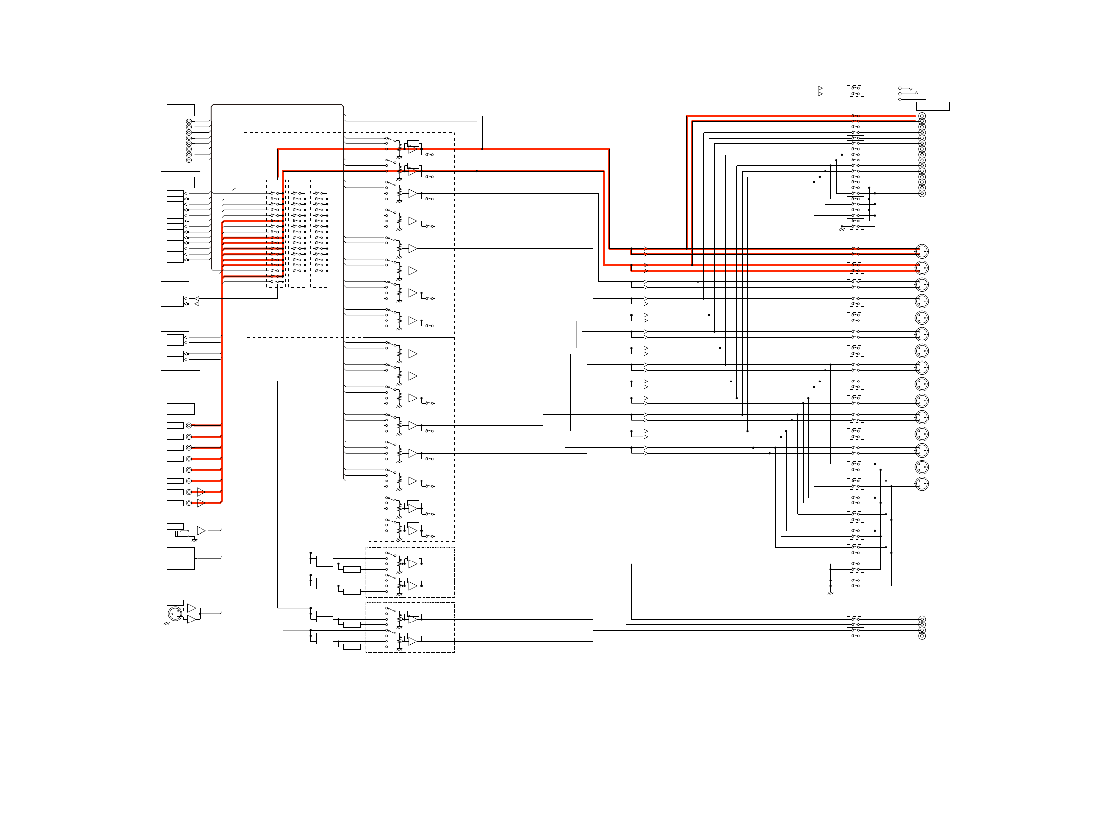
fig.01
AV8802 BLOCK DIAGRAM (A.AUDIO/Z2,3HPF)
TO
DIGITAL
AUDIO
BLOCK
DIAGRAN
8ch EXT.IN
FL
FR
C
SW
SL
SR
EXT-SBL
SBL
EXT-SBR EXT-FR
SBR
DAC OUT
FL
FR
C
SW1
SW2
SL
SR
SBL
SBR
FWL
FWR
FHL
FHR
(For Signal DET)
ADC INPUT
MAIN AD-L
MAIN AD-R
ZONE DAC OUT
Z2DA-L
Z2DA-R
Z3DA-R
AUDIO
INPUT
GAME
CD
DVR
SAT/CBL
DVD
BD
V.AUX
PHONO
MIC
EXT-FL
EXT-FR
EXT-C
EXT-SW
EXT-SL
EXT-SR
(For Zone2/3)
DA-FL
DA-FL/FR
DA-FR
DA-C
DA-SW1
DA-SW2
DA-SL
DA-SR
DA-SBL
DA-SBR
DA-FWL
DA-FWR
DA-FHL
DA-FHR
GAME
DVR
SAT/CBL
DVD
V.AUX
PHONO
MIC
CD
BD
Z2L
/R
Z3L
/R
MX
XLR
V.AUX
MIC
TUNER
PHONO
CD
BD
DVD
SAT/CBL
GAME
EXT-FL/FR
DVR
DVR-REC
VOLUME IC1
R2A15220FP
MAIN
(MAIN)
(IN1L/R)
(IN2L/R)
(IN3L/R)
(IN4L/R)
(IN5L/R)
(IN6L/R)
(IN7L/R)
(IN8L/R)
(INAL/R)
(IN9L/R)
(INBL/R)
(IN10L/R)
(IN11L/R)
(IN12L/R)
(IN13L/R)
(IN14L/R)
(REC3L/R)
MAIN-L
(ADCR)
MAIN-R
(ADCL)
ZONE2
(SUB1)
Z2LLINE(SUBR1)
ZONE3
(SUB2)
Z2RLINE
(SUBL1)
Z3LLINE
(SUBR2)
(SUBL2) Z3RLINE
PRE_FL
PRE_FR
EXT-FL
DA-FL
DA-FR
EXT-C
DA-C
EXT-SW
DA-SW1
EXT-SW
DA-SW2
EXT-SL
DA-SL
EXT-SR
DA-SR
PRE_FL
DA-FHL
PRE_FR
DA-FHR
PRE_FL
DA-FWL
PRE_FR
DA-FWR
PRE_FL
DA-SBL
EXT-SBL
PRE_FR
DA-SBR
EXT-SBR
(FLIN1)
(FLIN2)
(2chLIN)
(FRIN1)
(FRIN2)
(2chRIN)
(SLIN1)
(SLIN2)
(SBLCIN)
(SLCIN)
(SRIN1)
(SRIN2)
(SBRCIN)
(SRCIN)
(CIN1)
(CIN2)
(SWIN1)
(SWIN2)
(SBLIN1)
(SBLIN2)
(SBLCIN)
(SLCIN)
(SBRIN1)
(SBRIN2)
(SBRCIN)
(SRCIN)
(CIN1)
(CIN2)
(SWIN1)
(SWIN2)
(SLIN1)
(SLIN2)
(SBLCIN)
(SLCIN)
(SRIN1)
(SRIN2)
(SBRCIN)
(SRCIN)
(SBLIN1)
(SBLIN2)
(SBLCIN)
(SLCIN)
(SBRIN1)
(SBRIN2)
(SBRCIN)
(SRCIN)
(FLIN1)
(FLIN2)
(2chLIN)
(FRIN1)
(FRIN2)
(2chRIN)
TONE
FL
TONE
FR
C
RSV
SW1
SW2
SL
SR
VOLUME IC2
FWLZ3DA-L
FWR
FHL
FHR
SBL
SBR
TONE
Z2L
TONE
Z2R
(FLOUT)
(FLPRE)
(FROUT)
(FRPRE)
(SLOUT)
(SLPRE)
(SROUT)
(SRPRE)
(COUT)
(SWOUT)
(SBLOUT)
(SBLPRE)
(SBROUT)
(SBRPRE)
R2A15220FP
(COUT)
(SWOUT)
(SLOUT)
(SLPRE)
(SROUT)
(SRPRE)
(SBLOUT)
(SBLPRE)
(SBROUT)
(SBRPRE)
(FLOUT)
(FLPRE)
(FROUT)
(FRPRE)
PREOUT
FL
PREOUT
FR
PREOUT
C
C
AMPIN
PREOUT
RSV
PREOUT
SW1
PREOUT
SW2
PREOUT
SL
AMPIN
PREOUT
SR
AMPIN
PREOUT
FWL
PREOUT
FWR
PREOUT
FHL
PREOUT
FHR
PREOUT
SBL
PREOUT
SBR
+
-
+
-
+
-
+
-
+
-
+
-
+
-
+
-
+
-
+
-
+
-
+
-
+
-
Lch
2
Rch
3
G
1
H/P OUT
PREOUT
PRE_FL
PRE_FR
PRE_C
PRE_SW1
PRE_SW2
PRE_SL
PRE_SR
PRE_SBL
PRE_SBR
PRE_FWL
PRE_FWR
PRE_HL1
PRE_HR1
PRE_HL2
PRE_HR2
+
G
PRE_FL
-
+
G
PRE_FR
-
+
G
PRE_C
-
+
G
PRE_SW1
-
+
G
PRE_SW2
-
+
G
PRE_SL
-
+
G
PRE_SR
-
+
G
PRE_SBL
-
+
G
PRE_SBR
-
+
G
PRE_FWL
-
+
G
PRE_FWR
-
+
G
PRE_HL1
-
+
G
PRE_HR1
-
+
G
PRE_HL2
-
+
G
PRE_HR2
-
TUNER:
NA/EU/AP
ALL MODEL
XLR
TUNER
XLR
MONO
HPF
MONO
HPF
MONO
HPF
MONO
HPF
MONO
MONO
MONO
MONO
FULL
MONO
HPF
HPF+MONO
FULL
MONO
HPF
HPF+MONO
FULL
MONO
HPF
HPF+MONO
FULL
MONO
HPF
HPF+MONO
TONE
TONE
TONE
TONE
ZONE2
NJW1194
ZONE3
NJW1194
PREOUT
Z2L
PREOUT
Z2R
PREOUT
Z3L
PREOUT
Z3R
29
PRE_Z2L
PRE_Z2R
PRE_Z3L
PRE_Z3R
From/To ANALOG AUDIO BLOCK DIAGRAM
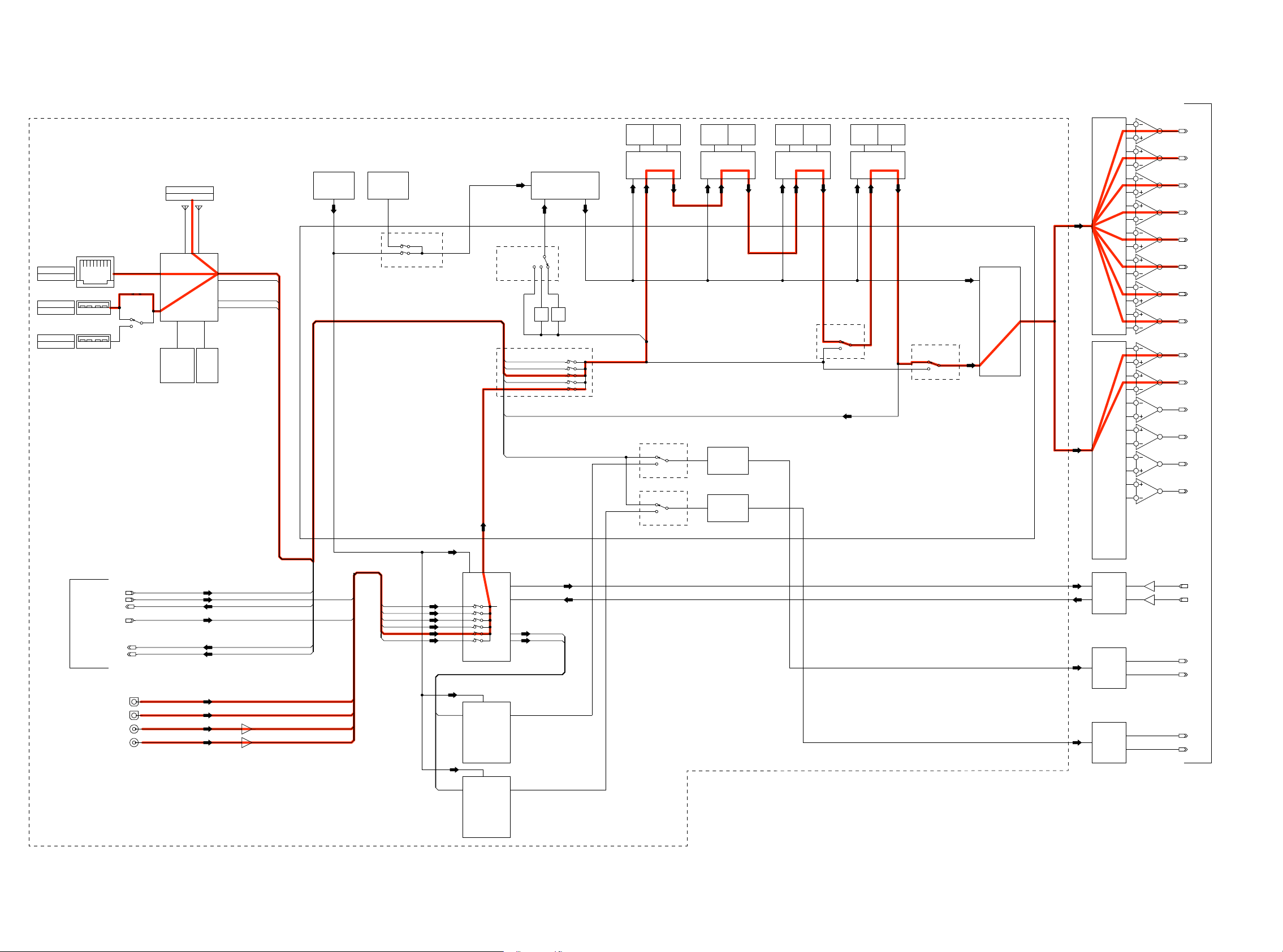
fig.02a
AV8802 DIGITAL AUDIO/NETWORK BLOCK DIAGRAM
DIGITAL PCB BLOCK
Wireless Network
Input
Wired Network
Input
USB-A
Input(FRONT)
USB-A
Input(REAR)
Netowrk Module
CX870/CY920
iPod
Coprocessor
S.Flash
I2S_CX870/CY920
DSD_CX870/CY920
CX870/CY920_VBUclk
CX870/CY920_VBUSdata(8bit)
FCXO-05
24.576MHz
FCXO-05
25.0MHz
REFCLK
Ref clock Sel.
fs Assign Sel.
DSP1 INPUT MU
I2S_HDMIRX
DSD_HDMIRX
I2S_CX870/CY920
DSD_CX870/CY920
DIR_I2S
I2S_HDMITX
I2S_CX870/CY920
Jitter Reducer PLL
CS2100
1/2
1/4
Div.
Div.
X
1 2
1 2
1 2
1 2
1 2
PLLOUT
DSP1_IN_LRCK
SDRAM FLASH FLASH HSALFMARDSMARDS
DSP1_IN
1st DSP
ZONE2 I2S MUX
1
3
2
ZONE3 I2S MUX
1
3
2
SDRAM
ADSP-21487
ZONE2
Mute Logic
ZONE3
Mute Logic
2nd DSP
FLASH
Z2DAC_I2S
Z3DAC_I2S
3rd DSP
78412-PSDA78412-PSDA
DSP3 INPUT MUX
6
5
4th DSP
ADSP-21487
3
2
6
5
MAIN DAC1
AK4490
3
2
6
5
3
2
6
5
Main ZONE
Mute Logic
1
3
2
DAC INPUT MUX
1
3
2
3
2
6
5
3
2
6
5
MAIN DAC2
AK4490
3
2
6
5
3
2
OUTPUT
7
DA_FL
OUTPUT
1
DA_FR
OUTPUT
7
DA_C
OUTPUT
1
DA_SW1
OUTPUT
7
DA_SW2
OUTPUT
1
DA_RSV
OUTPUT
7
DA_SL
OUTPUT
1
DA_SR
OUTPUT
7
DA_SBL
OUTPUT
1
DA_SBR
OUTPUT
7
DA_FHL
OUTPUT
1
DA_FHR
OUTPUT
7
DA_FWL
OUTPUT
1
DA_FWR
Audio PLD
5M570ZF256C5N
I2S/DSD_HDMIRX
SPDIF_HDMIRX
I2S_HDMITX
SPDIF_Z2HDMI
From/To VIDEO BLOCK DIAGRAM
CX870/CY920_VBUclk
CX870/CY920_VBUSdata(8bit)
OPT1
OPT2
COAX1
COAX2
INPUT
INPUT
OUTPUT
INPUT
OUTPUT
OUTPUT
I2S/DSD_HDMIRX
I2S_HDMITX
CX870/CY920_VBUclk
CX870/CY920_VBUSdata(8bit)
SPDIF_HDMIRX
SPDIF_Z2HDMI
COAX1
COAX2
OPT1
OPT2
SPDIF_HDMIRX
Main DIR
PCM9211
ADCCLK
SDATA
Z2_SPDIF
MAIN ADC
AK5358B
FIDPS_3ZIMDH2Z_FIDPS
ZONE2 DAC
PCM5100
INPUT
ADIN_FL
INPUT
ADIN_FR
OUTPUT
Z2DA_L
OUTPUT
Z2DA_R
OPT1
OPT2
COAX1
COAX2
Z2_SPDIF
Z3_SPDIF
ZONE2 DIR
LC89091JH
ZONE3 DIR
Z2DIR_I2S
Z3DIR_I2S
ZONE2 DAC
PCM5100
OUTPUT
Z3DA_L
OUTPUT
Z3DA_R
LC89091JH
30
 Loading...