


R
Model CD110 User Guide
CD Player
CLASS 1 LASER PRODUCT
KLASSE 1 LASER PRODUKT
I.H.T. IEC 825
CAUTION
RISK OF ELECTRIC SHOCK
DO NOT OPEN
CAUTION: TO REDUCE THE RISK OF ELECTRIC SHOCK,
DO NOT REMOVE COVER (OR BACK)
NO USER-SERVICEABLE PARTS INSIDE
REFER SERVICING TO QUALIFIED SERVICE PERSONNEL
The lightning flash with arrowhead symbol, within
an equilateral triangle, is intended to alert the user
to the presence of uninsulated “dangerous voltage”
within the product’s enclosure that may be of sufficient magnitude to constitute a risk of electric shock
to persons.
The exclamation point within an equilateral triangle
is intended to alert the user to the presence of
important operating and maintenance (servicing)
instructions in the literature accompanying the
appliance.
WARNING
TO REDUCE THE RISK OF FIRE OR ELECTRIC SHOCK,
DO NOT EXPOSE THIS APPLIANCE TO RAIN OR MOISTURE.
CAUTION: TO PREVENT ELECTRIC SHOCK, MATCH WIDE
BLADE OF PLUG TO WIDE SLOT, FULLY INSERT.
ATTENTION: POUR ÉVITER LES CHOCS ÉLECTRIQUES,
INTRODUIRE LA LAME LA PLUS LARGE DE LA FICHE DANS
LA BORNE CORRESPON-DANTE DE LA PRISE ET POUSSER
JUSQU’AU FOND.
LASER SAFETY
This unit employs a laser. Only a qualified service person should remove
the cover or attempt to service this device, due to possible eye injury.
CAUTION :
USE OF CONTROLS OR ADJUSTMENTS
OR PERFORMANCE OF PROCEDURE
OTHER THAN THOSE SPECIFIED HEREIN
MAY RESULT IN HAZARDOUS RADIATION
EXPOSURE.
i
SAFETY
INSTRUCTIONS
READ BEFORE OPERATING EQUIPMENT
This product was designed and manufactured to meet
strict quality and safety standards. There are, however,
some installation and operation precautions which you
should be particularly aware of.
1. Read Instructions — All the safety and operating instructions should be read before the appliance is
operated.
2. Retain Instructions — The safety and operating instructions should be retained for future reference.
3. Heed Warnings — All warnings on the appliance
and in the operating instructions should be adhered
to.
4. Follow Instructions — All operating and use instructions should be followed.
5. Water and Moisture — The appliance should not be
used near water — for example, near a bathtub,
wash-bowl, kitchen sink, laundry tub, in a wet
basement, or near a swimming pool, etc.
6. Carts and Stands — The appliance should be used
only with a cart or stand that is recommended by the
manufacturer.
7. An appliance and cart combination should be
moved with care. Quick stops, excessive force, and
uneven surfaces may cause the appliance and cart
combination to overturn.
8. Wall or Ceiling Mounting — The appliance should
be mounted to a wall or ceiling only as recommended by the manufacturer.
9. Ventilation — The appliance should be situated so
that its location or position does not interfere with its
proper ventilation. For example, the appliance
should not be situated on a bed, sofa, rug, or similar
surface that may block the ventilation openings; or,
placed in a built-in installation, such as a bookcase
or cabinet that may impede the flow of air through
the ventilation openings.
10. Heat — The appliance should be situated away
from heat sources such as radiators, heat registers,
stoves, or other appliances (including amplifiers)
that produce heat.
11. Power Sources — The appliance should be connected to a power supply only of the type described
in the operating instructions or as marked on the
appliance.
12. Grounding or Polarization — The precautions that
should be taken so that the grounding or polarization
means of an appliance is not defeated.
AC POLARIZED PLUG
13. Power-Cord Protection — Power-supply cords
should be routed so that they are not likely to be
walked on or pinched by items placed upon or
against them, paying particular attention to cords at
plugs, convenience receptacles, and the point where
they exit from the appliance.
14. Cleaning — The appliance should be cleaned only
as recommended by the manufacturer.
15. Power Lines— An outdoor antenna should be located away from power lines.
16. Outdoor Antenna Grounding — If an outside antenna
is connected to the receiver, be sure the antenna
system is grounded so as to provide some protection
against voltage surges and built up static charges.
Section 810 of the National Electrical Code, ANSI/
NFPA No. 70-1984, provides information with
respect to proper grounding of the mast and supporting structure, grounding of the lead-in wire to an antenna discharge unit, size of grounding conductors,
location of antenna-discharge unit, connection to
grounding electrodes, and requirements for the
grounding electrode. See Fig. 1.
17. Nonuse Periods — The power cord of the appliance
should be unplugged from the outlet when left
unused for a long period of time.
18. Object and Liquid Entry — Care should be taken so
that objects do not fall and liquids are not spilled into
the enclosure through openings.
19. Damage Requiring Service — The appliance should
be serviced by qualified service personnel when:
A. The power-supply cord or the plug has been
damaged; or
B. Objects have fallen, or liquid has spilled into the
appliance; or
C. The appliance has been exposed to rain; or
D. The appliance does not appear to operate
normally or exhibits a marked change in
performance; or
E. The appliance has been dropped, or the
enclosure damaged.
20. Servicing — The user should not attempt to service
the appliance beyond that described in the operating
instructions. All other servicing should be referred to
qualified service personnel.
ii
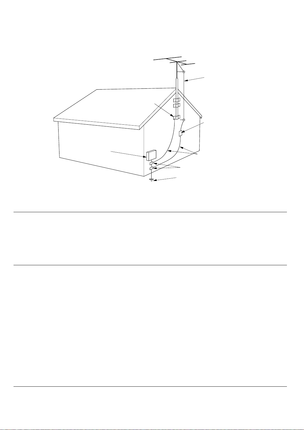
FIGURE 1
EXAMPLE OF ANTENNA GROUNDING ACCORDING TO
NATIONAL ELECTRICAL CODE INSTRUCYIONS
CONTAINED IN ARTICLE 810 -"RADIO AND TELEVISION EQUIPMENT"
ANTENNA LEAD
IN WIRE
GROUND CLAMP
ANTENNA
DISCHARGE UNIT
(NEC SECTION 810-20)
ELECTRIC
SERVICE
EQUIPMENT
POWER SERVICE GROUNDING
ELECTRODE SYSTEM
(NEC ART 250, PART H)
GROUNDING CONDUCTORS
(NEC SECTION 810-21)
GROUND CLAMPS
NEC - NATIONAL ELECTRICAL CODE
NOTE TO CATV SYSTEM INSTALLER:
This reminder is provided to call the CATV (Cable-TV) system installer's attention to Article 820-40 of
the NEC, which provides guidelines for proper grounding and, in particular, specifies that the cable
ground shall be connected to the grounding system of the building, as close to the point of cable entry
as practical.
NOTE:
This equipment has been tested and found to
comply with the limits for a Class B digital device,
pursuant to Part 15 of the FCC Rules. These limits
are designed to provide reasonable protection
against harmful interference in a residential installation. This equipment generates, uses and can
radiate radio frequency energy and, if not installed
and used in accordance with the instructions, may
cause harmful interference to radio communications. However, there is no guarantee that interference will not occur in a particular installation. If this
equipment does cause harmful interference to
radio or television reception, which can be determined by turning the equipment off and on, the
user is encouraged to try to correct the interference by one or more of the following measures:
– Reorient or relocate the receiving antenna.
– Increase the separation between the equip-
ment and receiver.
– Connect the equipment into an outlet on a
circuit different from that to which the receiver is
connected.
– Consult the dealer or an experienced radio/TV
technician for help.
NOTE:Changes or modifications may cause this
unit to fail to comply with Part 15 of the FCC Rules
and may void the user's authority to operate the
equipment.
This Class B digital apparatus complies
with Canadian ICES-003.
Cet appareil numérique de la Classe B est
conforme á la norme NMB-003 du Canada.
iii
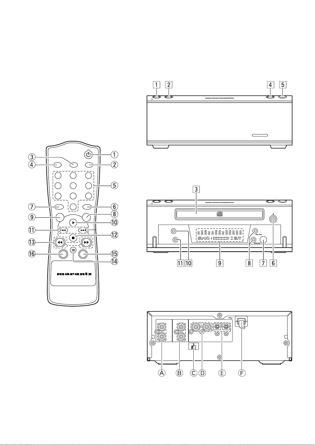
MAIN UNIT (FRONT - CLOSED)
zx vb
STANDBY 7 6 OPEN
REMOTE CONTROL UNIT
e
AMS
SCROLL
r
2
1
5
4
8
7
RANDOM
u
0
CD TEXT TIMER
o
!1
!3
!6
CANCEL
REMOTE CONTROLLER
RC110CD
DISPLAY
REPEAT
3
6
9
PROG.
q
w
t
y
i
!0
!2
!5
!4
MAIN UNIT (FRONT - OPENED)
c
STANDBY 7 6 OPEN
REPEAT
DISPLAY
Ú0
MAIN UNIT (REAR)
.mnÚ1
,
CD110
iv
ANALOG OUT
REMOTE CONTROL
LEFT
IN
RIGHT OUT
REMOTE
CONTROL
SELECTOR
COAX.— — OPT.
EXT.
INT.
ACDEFB
DIGITAL OUT

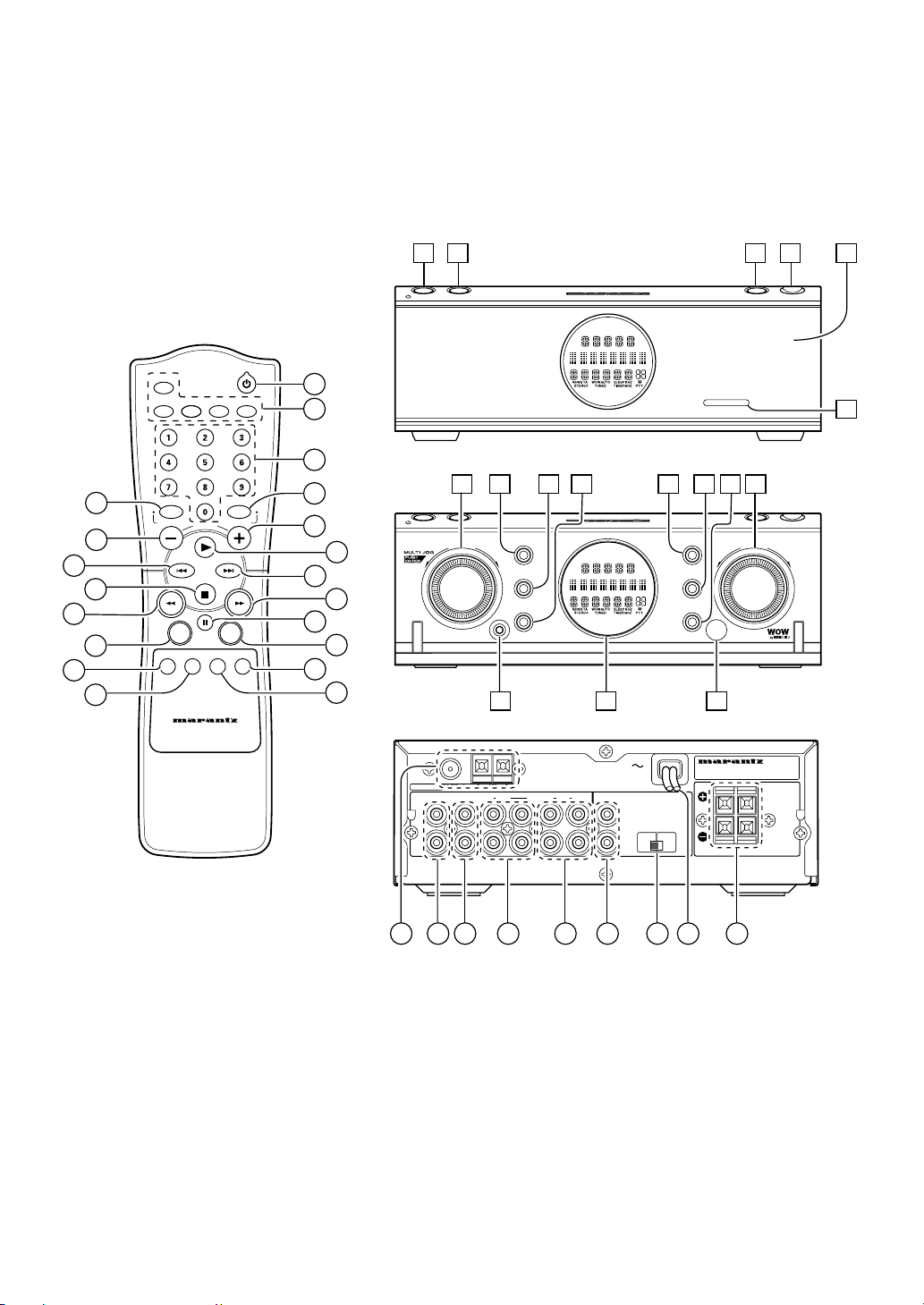
ABOUT THIS USER GUIDE
Refer to the figures on page iv of this user guide. The numbers
on the figures correspond to those in the text. All references to
the connections and controls that are printed in BOLD type are
as they appear on the unit.
PRECAUTIONS
The following precautions should be taken when operating the
equipment.
GENERAL PRECAUTIONS
When installing the equipment ensure that:
– the ventilation holes are not covered.
– air is allowed to circulate freely around the equipment.
– it is placed on a vibration-free surface.
– it will not be exposed to excessive heat, cold, moisture or
dust.
– it will not be exposed to direct sunlight.
– it will not be exposed to electrostatic discharges.
In addition, never place heavy objects on the equipment.
If a foreign object or water does enter the equipment, contact
your nearest dealer or service center.
Do not pull out the plug by pulling on the mains lead; grasp the
plug.
It is advisable when leaving the house, or during a
thunderstorm, to disconnect the equipment from the mains
supply.
ENGLISH
1
COMPACT DISCS
ENGLISH
The glossy side shining like a rainbow is the front side of the
disc, and the side on which the label is printed is the back.
Unlike conventional turntables for playing analog discs, the
CD110 Compact Disc Player reads the information recorded
on the disc from underneath without contacting it using a beam
of laser light. Therefore, the performance of a compact disc will
not degrade like conventional analog records.
Handle discs carefully so as not to damage or scratch the front
side.
To protect the disc, avoid placing it in the following locations:
– In direct sunlight or near a source of heat like a heater.
– In a place which is damp or dirty.
– In a place which could be exposed to rain, such as near a
window.
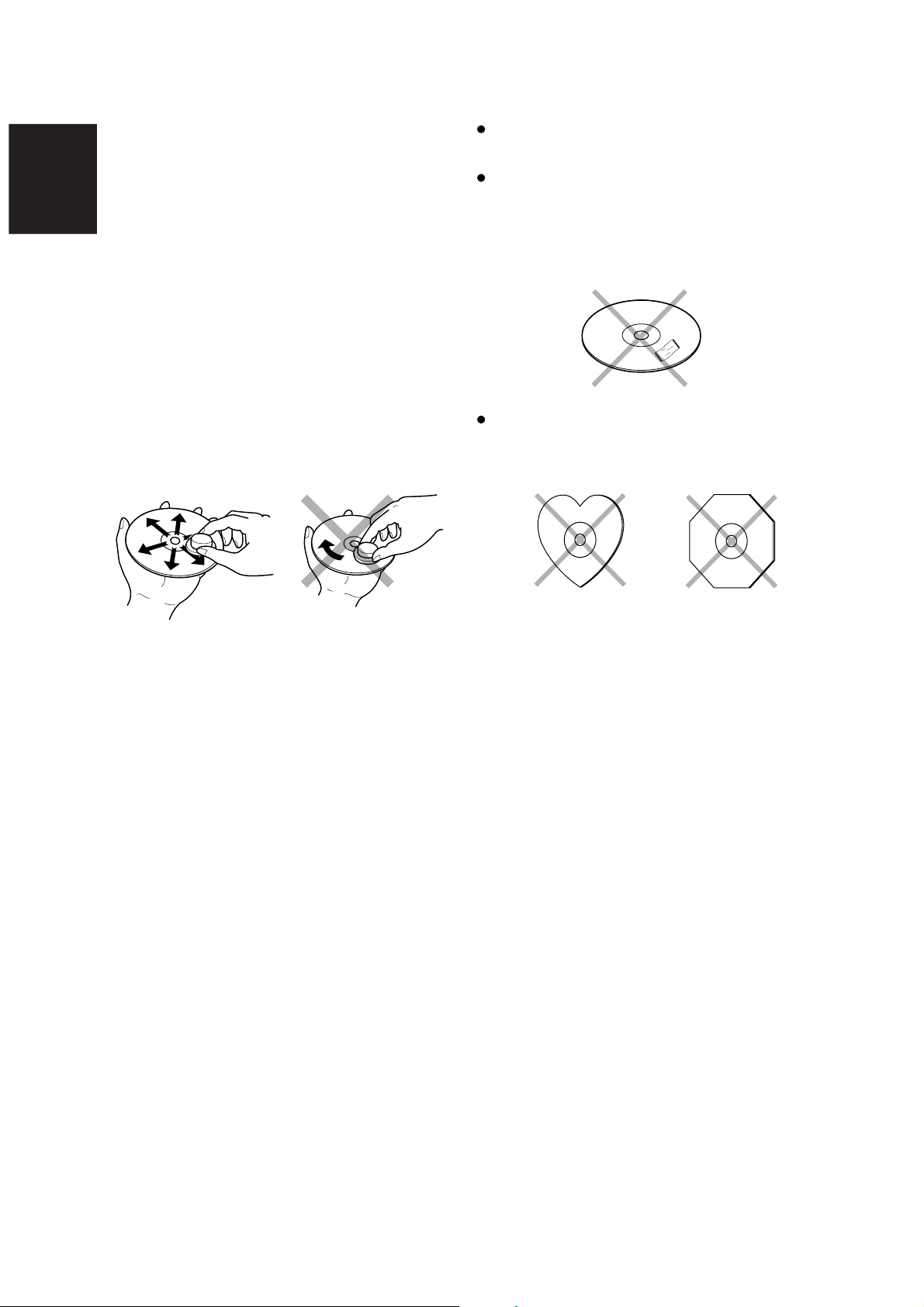
Always keep the disc surface clean.
Up to six billion data units are recorded on the front side of the
disc. When cleaning the disc surface, always be sure to use a
special compact disc cleaner and wipe as shown below.
Do not use conventional record cleaner for analog records,
as this will adversely affect the disc surface.
Store discs properly by placing them in their disc cases.
Do not attach a piece of paper or sticker on the label side of
disc.
When a disc has a piece of plastic tape or rental CD label
with paste protruded from the edge or when a disc has a
trace of such a sticky object, do not attempt to play the disc. If
such a disc is played on the CD player, impossibility of taking
out the disc or other malfunction may result.
Do not use a disc with a special shape.
Do not attempt to play a disc with a special shape such as a
heart-shaped disc or octagonal disc. Otherwise the
equipment malfunction may result.
Wipe in a radial direction. Do not wipe in circumferential
direction.
2

REMOTE CONTROL UNIT
q (Standby) button
Press to turn the unit's power on or set it to the standby mode.
(Operation is not possible if the unit is connected to the SR110,
the SR110's rear switch is set to SYSTEM and the CD110's
REMOTE CONTROL SELECTOR EXT/INT switch is at EXT.)
w DISPLAY button
Press to change what is shown on the display from the disc
information to the clock display, etc. (The clock display appears
only when the unit is used on its own.)
e SCROLL button
Press to scroll the text display of discs that support text.
!1 4, ¢ buttons
4 : Press to play from the start of the track now playing. When
they are pressed again within 1 second after it was
pressed the first time, play starts from the track before.
¢ : When pressed once, play starts from the next track.
!2 7 (Stop) button
Press to stop disc play.
!3 1, ¡ buttons
1 : Press to forward-search through the track now playing.
¡ : Press to reverse-search through the track now playing.
These buttons cannot be used during MP3 disc play.
ENGLISH
r AMS button
Press to play the first 10 seconds of all the tracks on the disc in
sequence starting with the first track.
t Numeric buttons
Press to specify track numbers directly. These buttons cannot be
used with MP3 discs.
y REPEAT button
Press for repeat play. Each time the button is pressed, the mode
changes in the following sequence:
All track repeat fi 1-track repeat fi clear.
u RANDOM button
Press for random play to play the tracks in a random sequence.
i TIMER button
Press to set the timer and clock. (These settings can be performed
only when the unit is used on its own.)
o CD TEXT button
Press to switch what is shown on the display from disc information
to text when a CD-TEXT compatible disc is used.
!0 3 (Play) button
Press to start play.
!4 8 (Pause) button
Press to stop disc play temporarily.
!5 PROG. button
Press for program play.
This button cannot be used with MP3 discs.
!6 CANCEL button
Press to cancel a programmed track.
3
OPERATION OF REMOTE CONTROL UNIT
ENGLISH
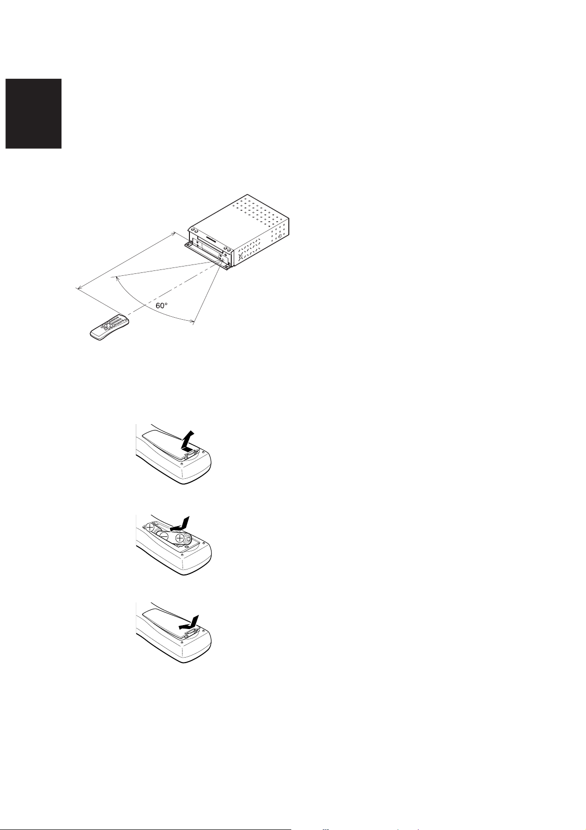
1. REMOTE CONTROL
The distance between the transmitter of the remote control unit
and the IR SENSOR of the CD110 should be less than about 5
meters. If the transmitter is pointed to a direction other than the
IR SENSOR or if there is an obstacle between them, remote
control may not be possible.
Remote-controllable range
CD player (CD110)
Approx. 5 meters
Remote control unit (RC110CD)
2. LOADING BATTERIES
The life of the batteries used with the remote control unit is
about 6 months with normal use. Also be sure to replace
batteries earlier when you notice that they are getting weak.
1. Remove the back cover.
2. Insert the new batteries (AA type) with correct (+) and (–)
polarity.
3. Close until it clicks.
4

REAR PANEL
FRONT PANEL
A ANALOG OUT jacks
These are the output jacks for the analog audio signals. Connect
them to the CD or AUX jacks, etc. on the amplifier using the
supplied analog connecting cord. Remember that the white jack
is for the LEFT channel and the red jack is for the RIGHT channel,
and connect the jacks correctly.
* Never connect these jacks to the PHONO jacks of the amplifier.
B REMOTE CONTROL IN/OUT jacks
The remote control operations of a system can be performed by
connecting the unit to a Marantz D-BUS compatible audio
component using the supplied remote control cable.
C REMOTE CONTROL SELECTOR
EXT./INT. switch
When the unit is to be used on its own, set this selector to "INT",
and when connecting the unit to Marantz audio components
equipped with a D-BUS compatible remote sensor window using
the remote control cable for use as part of a system, set the
selector to "EXT".
* Remote control operations cannot be performed if the REMOTE
CONTROL SELECTOR is set to "EXT" when the unit is to be
used on its own.
D DIGITAL OUT COAX. jacks
The CD signals during playback are output digitally to these jacks.
Connect these jacks to a recorder component, amplifier, D/A
converter or other unit equipped with coaxial digital input jacks
using a coaxial cable obtainable from your audio dealer.
E DIGITAL OUT OPT. jacks
The CD signals during playback are output digitally to these jacks.
Connect these jacks to a recorder component, amplifier, D/A
converter or other unit equipped with optical digital input jacks
using a square optical cable obtainable from your audio dealer.
F Power cord jack
Connect this to a household AC 120 V outlet.
z Standby button
Press to switch the power ON, and press again to switch it OFF.
* If the SR110 is connected to the REMOTE CONTROL jacks on
the rear panel and its power is ON, the unit will not be set to the
standby mode even when this button is pressed.
x 7 (Stop) button
Press to stop play.
c Disc tray
Place a disc on the tray with its label surface facing up.
v 6 (Play/Pause) button
Press to start play or temporarily stop play.
b OPEN button
Press to open the front panel.
n 0 (Open/Close) button
When this button is pressed, the disc tray opens so place the
disc on the tray with its label surface facing up. When it is pressed
again the disc tray closes.
m Infrared sensor
This sensor is for receiving signals transmitted from the remote
control unit.
, ¡
/
¢, 4 /
1
(Track search/Skip) buttons
¡
/
¢ : When pressed once, play starts from the next track.
When held down for more than one second, the track
being played is searched in the forward direction.
4
/
1 : When pressed once, play resumes from the start of
the track now playing. When it is pressed again
within 1 second after it was pressed the first time,
play starts from the track before.
When held down for more than one second, the track
being played is searched in the reverse direction.
ENGLISH
. Display panel
This panel displays the operating modes and statuses.
⁄0 REPEAT button
Press for repeat play. Each time the button is pressed, the mode
changes in sequence from "1-track repeat" fi "all track repeat"
fi "clear."
⁄1 DISPLAY button
Press to select the time display. Each time the button is pressed
during play, the display changes in sequence from "elapsed track
time" fi "remaining track time" fi "total remaining time" fi "clock
display" (when the unit is used on its own) fi "elapsed track time."
If this button is pressed in the standby mode when the unit is
being used on its own, the power-on mode is established for 10
seconds, during which time the clock display appears.
5
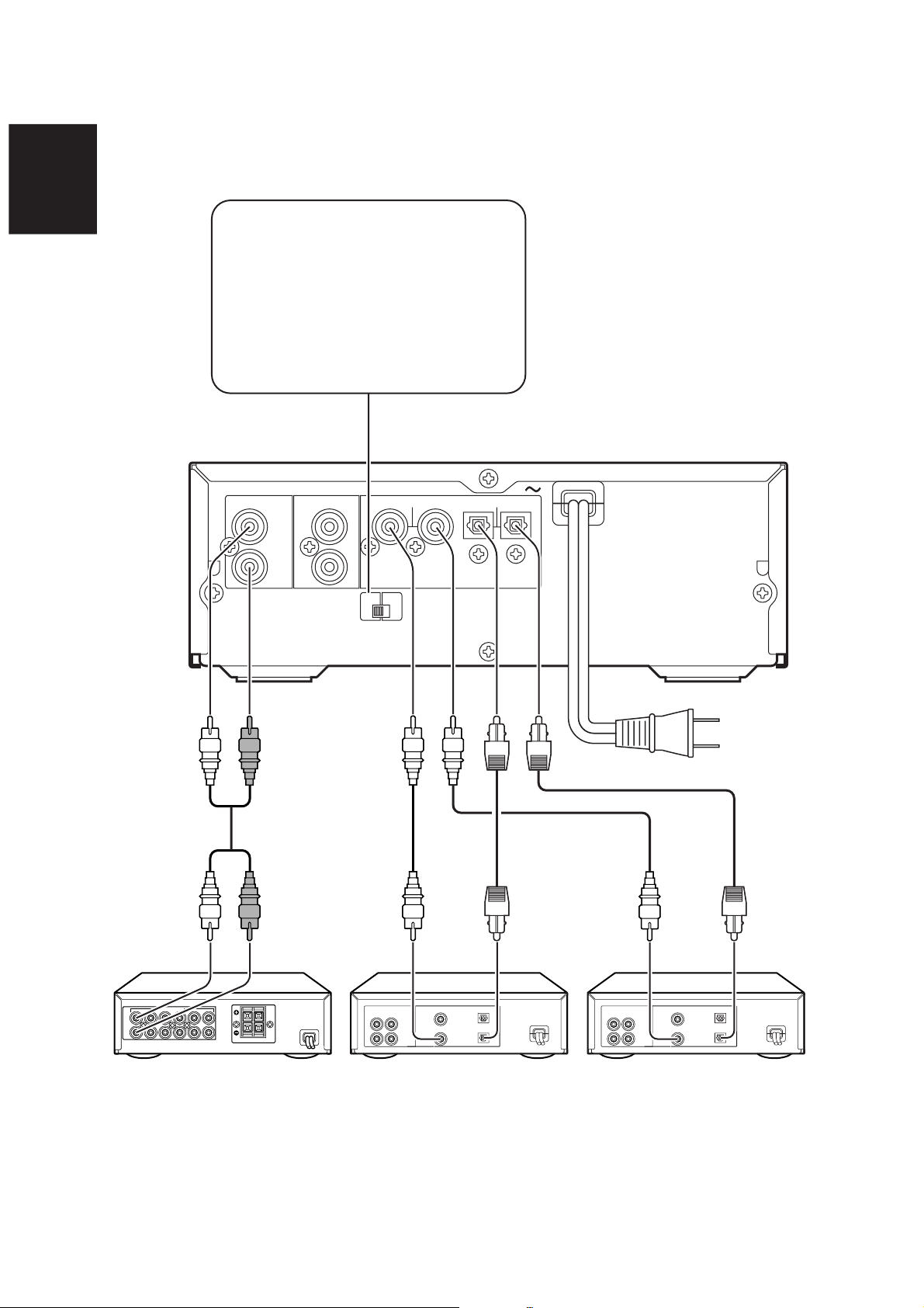
CONNECTIONS
ENGLISH
When this unit is to be used on its own, set the
REMOTE CONTROL SELECTOR to INT, and
when connecting the unit to Marantz audio
components equipped with a D-BUS compatible
remote sensor window using the remote control
cable for use as part of a system, set the REMOTE
CONTROL SELECTOR to EXT.
* Remote control operations cannot be performed if
the REMOTE CONTROL SELECTOR is set to
EXT when this unit is to be used on its own.
ANALOG OUT
LEFT
RIGHT OUT
REMOTE CONTROL
IN
REMOTE
EXT.
CONTROL
SELECTOR
INT.
DIGITAL OUT
COAX.— — OPT.
To power outlet
ANALOG IN
LEFT
RIGHT
LEFT
RIGHT
ANALOG
OUT IN
LEFT
RIGHT
DIGITAL COAX. OUT
DIGITAL COAX. IN
DIGITAL OPT OUT
DIGITAL OPT IN
ANALOG
OUT IN
LEFT
RIGHT
DIGITAL COAX. OUT
DIGITAL COAX. IN
DIGITAL OPT OUT
DIGITAL OPT IN
Amplifier CD-R recorder, etc.MD Deck, etc.
* If this unit is to be used as part of a system, refer to the SR110 User Guide.
6
CONCERNING CD-TEXT
A new type of music CD produced by recording the album
name, track names and other text information as well as music
on a conventional CD is called CD-TEXT.
The text information is recorded on parts which were not used
by conventional music CDs. For this reason, these CDs can be
still played back on existing CD players as in the past whereas
if a CD-TEXT compatible player such as this unit is used
instead, their text information can be viewed as well.
Using the accessory remote control unit, this unit enables the
album names and track names to be shown on the display
window. Depending on the disc, however, not all the
information may have been recorded.
With this unit, up to 13 characters of this information can be
displayed at one time. If the disc has more text information,
the characters are scrolled (see *) from right to left facing the
display window.
* Scrolling means moving through the text which is being
displayed.
This unit supports only alphanumerics and symbols: Chinese
characters ('kanji'), hiragana and katakana are not displayed.
(Nothing appears on the display when the text information
consists solely of Chinese characters, hiragana and
katakana.)
By pressing the CD TEXT button on the remote control unit,
the following items of TEXT information on a CD-TEXT disc
can be displayed in sequence.
– During play:
Each time the button is pressed, what is displayed is
switched between the name of the track being played and the
time.
– In the stop mode:
Each time the button is pressed, what is displayed is
switched between the album's title and the time.
CONCERNING CD-RW DISC
PLAY
In addition to conventional music CDs and CD-R (Recordable)
discs, this unit can also play CD-RW (ReWritable) discs.
The TOC (see *) must have been recorded correctly for CD-R
or CD-RW playback. Writing the TOC information using a
CD recorder is known as finalizing. Bear in mind that if the
finalizing work has not been completed correctly for a disc,
the disc will not be recognized correctly as a music CD by a
regular CD player and will not be played. For further details,
refer to the Instruction Manual of the CD recorder.
* TOC stands for table of contents which consists of the total
number of tracks on a disc, the total play time and other
data.
Playable discs include only those discs recorded in the CDDA format for music applications. Do not attempt to play CDROMs for personal computers and other discs on which data
has been recorded.
Since some of the player's settings are changed when a CDRW disc is played, it may take a little longer to read the TOC
than a music CD or CD-R disc.
"CD-RW" appears on the display when a CD-RW disc is
recognized.
TRACK TRACK TIME
CD — RW
This lights.
In some cases, due to compatibility issues, it may not be
possible to play a CD-R(W) disc that has been finalized.
(This problem frequently occurs when material that was
recorded at 2x is played back and recorded at 2x yet again.)
ENGLISH
7
CD PLAY
ENGLISH
1. Press the button q/z to switch on the power.
* The CD110's power will also be switched on if the SR110
is connected to the REMOTE CONTROL jack and the
SR110's power is on.
2. Press the OPEN button b to open the panel.
3. Press the 0 button n.
The disc tray is now extended so place the disc on the tray
with its label surface facing up.
4. Press the 0 button n.
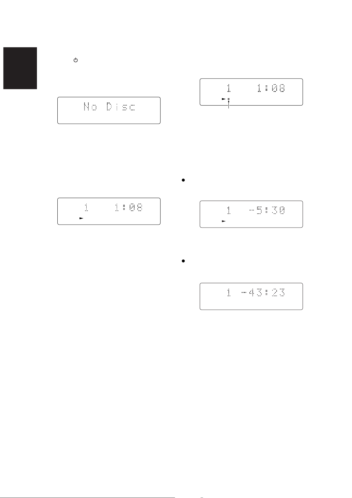
5. Press the 6 button v on the main unit or the 3 button !0
on the remote control unit. If track 1 has been playing for 1
minute and 8 seconds, for instance, the following will
appear on the main display during play.
TRACK TRACK TIME
TO TEMPORARILY STOP PLAY
Press the 6 button v on the main unit or the 8 button ⁄4 on
the remote control unit.
The pause indicator (8) lights, and the disc play is temporarily
stopped where the button was pressed.
TRACK TRACK TIME
CD
This lights.
To resume play, press the 6 button v on the main unit or the
3 !0 or 8 !4 button on the remote control unit.
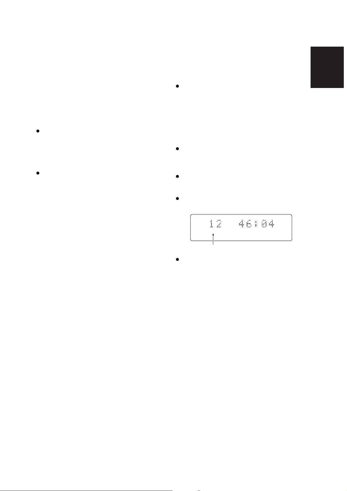
TO SWITCH THE TIME DISPLAY
Press the DISPLAY button during play. Each time this button is
pressed, the display changes in sequence from "elapsed track
time" fi "remaining track time" fi "total remaining time" fi
"clock display" (when the unit is used on its own) fi "elapsed
track time."
Remaining track time
(Remaining play time from the part of the track now playing to
the end of the same track)
TRACK REM TRACK TIME
CD
Play stops automatically when the last track has been
played.
TO PLAY THE DISC AGAIN STARTING FROM THE
FIRST TRACK
Press the 6 button v on the main unit or the 3 button !0 on
the remote control unit.
TO STOP PLAY
Press the 7 button !2/x.
TO REMOVE THE DISC
Press the 0 button n to open the disc tray, remove the disc,
and press the button again to close the disc tray. Keep the disc
tray closed without fail when the unit is not going to be used.
CD
When playing a disc that contains more than 30 tracks, the
"--:--" will be displayed as the remaining track time for track
31 and subsequent tracks.
Total remaining time
(Remaining play time from the part of the track now playing to
the end of the last track on the disc)
TRACK TOTAL REM TIME
8

SEARCHING/SKIPPING
REPEAT PLAY
DIRECT SEARCH (SPECIFYING THE NUMBER
OF A DESIRED TRACK AND PLAYING IT)
1. Specify the track number using the numeric buttons (0 to
9).
Track 3 : Press numeric button "3."
Track 12 : Press numeric button "1" and then numeric
button "2" within two seconds.
* This operation does not work with MP3 discs.
2. Press the 6 button v on the main unit or the 3 button !0
on the remote control unit.
TRACK SKIPPING (4, ¢)
TO HEAR ONE OF THE TRACKS AFTER THE ONE
NOW PLAYING
Press the ¡/¢ button , on the main unit or the ¢ button
!1 on the remote control unit for the same number of times as
the number of tracks to be skipped.
TO HEAR ONE OF THE TRACKS PRECEDING THE
ONE NOW PLAYING
Press the 4/1 button , on the main unit or the 4 button
!1 on the remote control unit for the same number of times as
the number of tracks to be skipped.
* When the 4/1 button , or ¡/¢ button , on the main
unit is held down for more than one second, the track now
playing is searched in the reverse or forward direction.
1-TRACK REPEAT (REPEATED PLAYBACK OF
ONE TRACK ONLY)
Press the REPEAT button y/⁄0 once while the track you want
to repeat is playing.
The "REPEAT" indicator lights, and the track is played
repeatedly.
TRACK TRACK TIME
CD
REPEAT
This lights.
TO RETURN TO NORMAL PLAY
Press the REPEAT button y/⁄0 twice. The "REPEAT" indicator
goes off, the repeat mode is cleared, and normal play is
restored.
ALL TRACK REPEAT (REPEATED PLAYBACK
OF ALL TRACKS ON THE DISC)
When the REPEAT button y/⁄0 is pressed twice, the "REPEAT"
and "ALL" indicators light, and all the tracks are played
repeatedly.
TRACK TRACK TIME
CD
REPEAT
ALL
ENGLISH
These light.
TO RETURN TO NORMAL PLAY
Press the REPEAT button y/⁄0 once. The "REPEAT" and
"ALL" indicators go off, the repeat mode is cleared, and normal
play is restored.
* When all track repeat is selected after programming, only the
tracks selected will be played repeatedly.
The all track repeat mode remains established at all times
with MP3 discs. The "ALL" indicator does not light in this
case. Only 1-track repeat can be selected.
Note:
If the RANDOM u or AMS r button is pressed during repeat
play, the repeat play setting is cancelled.
9

RANDOM PLAY
ENGLISH
When the RANDOM button u is pressed during play or stop,
the unit automatically rearranges the sequence of the tracks
and plays all the tracks in the resulting random order.
This lights.
TRACK TRACK TIME
CD
RANDOM
AMS PLAY
When the AMS button r is pressed with a regular CD in the
stop mode, the "SCAN" indicator lights, and the first ten
seconds of each track on the disc starting from the first track
are played in succession.
If the AMS button r is pressed during play, the first ten
seconds of each track on the disc starting from the track now
playing are played in succession.
This function comes in handy for finding particular tracks to be
played.
This lights.
* If the RANDOM button u is pressed with a disc placed on the
disc tray while the tray is open, the disc tray will close and
random play will begin.
TO STOP RANDOM PLAY AND RETURN TO
NORMAL PLAY
Press the RANDOM button u again.
TO MOVE TO THE NEXT TRACK IN THE RANDOM
SEQUENCE
Press the ¡/¢ button , on the main unit or ¢ button !1
on the remote control unit.
Each time one of these buttons is pressed, operation moves to
the next track in the random sequence and starts playing it.
TO SEARCH FOR A SECTION OF THE TRACK NOW
PLAYING
During random play, either hold down the 4/1 or ¡/¢
button , on the main unit for at least 1 second or hold down the
1 or ¡ button !3 on the remote control unit.
The search operation will not move to a track before or after the
track now playing.
TO REPEAT RANDOM PLAY
Press the REPEAT button y/⁄0 twice. The "REPEAT" and
"ALL" indicators light on the display, and the same tracks are
played repeatedly each time in a different random order.
* If the AMS button r is pressed during random play, the
random play setting is cancelled.
TRACK TRACK TIME
CD
Once the track to be played has been found, press the AMS
button r again. The "SCAN" indicator goes off, and all the
tracks starting with the located track are played in the normal
play mode.
* If the RANDOM button u is pressed during AMS play, the
AMS play setting is cancelled.
Note
If the AMS button r is pressed when an MP3 disc is being
played, the “AMS” indicator lights and AMS play applies only to
the
files in the directory that is being played back.
If the “AMS” and “ALL” indicators light, AMS play applies to the
files in all the directories.
SCAN
This lights.
Note
If the RANDOM button u is pressed when an MP3 disc is being
played, the “RANDOM” indicator lights and random play applies
only to the files in the directory that is being played back.
If the “RANDOM” and “ALL” indicators light, random play
applies to the files in all the directories.
10

PROGRAM PLAY
LISTENING TO FAVORITE TRACKS IN A FAVORITE
ORDER
This function cannot be used with MP3 discs.
– Random play cannot be used with program play.
– AMS cannot be used with program play.
1. When the PROG. button !5 is pressed in the stop mode,
the "PROG" indicator flashes, and the program mode is
established.
TRACK TOTAL TIME
TO CHECK THE PROGRAM CONTENTS
Press the PROG. button !5 during programming.
Each time this button is pressed, the tracks will be displayed
one after the other in the sequence in which they were
programmed.
ENGLISH
TO CLEAR A PROGRAMMED TRACK
Press the CANCEL button !6 during programming.
Each time this button is pressed, the tracks will be deleted one
at a time in sequence starting with the one programmed last.
TO CLEAR THE ENTIRE PROGRAM
To clear the entire program, either press the 0 button n on the
main unit, or else press the CANCEL button !6 on the remote
control unit three times.
CD
PROG
flashes
2. Select the tracks to be programmed using the numeric
buttons or 4 and ¢ buttons !1 on the remote control
unit. (They can also be selected using the 4/1 and
¡/¢ buttons , on the main unit.)
When the tracks are to be selected using the 4 and ¢
buttons !1 on the remote control unit (or 4/1 and ¡/
¢ buttons , on the main unit), first select the tracks, and
then press the PROG. button !5.
* To input a 2-digit track number to select a track using the
numeric buttons, first input the 10's digit and, within 2
seconds, input the 1's digit.
(Example: When selecting track number 5 as the first track
and its play time is 3 min. 39 sec.)
Track number
TRACK TOTAL TIME
CD
Program number
PROG
TO ADD TO THE PROGRAM
Select the track or tracks to be added using the numeric buttons
or the 4 and ¢ buttons !1 on the remote control unit (or
4/1 and ¡/¢ buttons , on the main unit) while the unit
is in the stop mode (while "PROG" is lighted) when there is
room for more tracks in the program.
To select a track using the 4 and ¢ buttons !1 on the
remote control unit (or 4/1 and ¡/¢ buttons , on the
main unit), first select the track, and then press the PROG.
button !5.
The newly added track is added to the end of the program.
If, when using the numeric buttons to select tracks 1
through 9 on a disc with 10 or more tracks in total, track
number 3 is to be selected after track number 1, for
example, first press the numeric button "1" and then wait at
least 2 seconds before pressing "3."
When selecting track number 10 or higher such as track
number 13, first press the numeric button "1" and then
press "3" before allowing 2 seconds to elapse.
When using the 4 and ¢ buttons !1 on the remote
control unit (or 4/1 and ¡/¢ buttons , on the
main unit) for programming, first select the number of the
desired track, and then press the PROG. button !5 to enter
it.
REPEAT DURING PROGRAM PLAY
If all track repeat is selected, all of the tracks in the program are
repeated, not all of the tracks on the disc.
TRACK TOTAL TIME
CD
PROG
3. Then, repeat step 2 for the next track and so on to program
up to 30 tracks.
4. Upon completion of all the programming, press the 3
button !0.
The selected tracks are now played in the programmed
order.
Note:
If track 31 or higher is included in a program, the time display
will read "--:--" from that point on.
If the program total time exceeds 99 minutes, the time
display will read "--:--".
11

USING THE TIMER
ENGLISH
FUNCTIONS
This unit enables a time to be set and for a disc to be played at
this setting. The clock must always be set for the timer
functions to be valid.
* These functions work only when the unit is used on its own.
The SR110's timer functions are used when the unit is
operating as part of a system with the SR110.
7. Press the 7 button !2/x to enter the selection.
The time set on the display now flashes. (Second setting)
This flashes.
This flashes.
SETTING THE TIME
1. Press the TIMER button i on the remote control unit for at
least 3 seconds.
"12/24" now appears on the display, and "12" starts
flashing.
This flashes.
2. Select the 12-hour or 24-hour time display using the 4
and ¢ buttons !1 on the remote control unit or the 4/
1 and ¡/¢ buttons , on the main unit.
3. Press the 7 button !2/x to enter the selection.
The time now appears on the display, and the hour flashes.
(Hour setting)
This flashes.
4. Set the current hour using the 4 and ¢ buttons !1 on
the remote control unit or the 4/1 and ¡/¢ buttons
, on the main unit.
8. Finally when the stop button on the remote control unit is
pressed, the time starts from 00 seconds. The entered
time appears for 3 seconds, and then the original display is
restored.
5. Press the 7 button !2/x to enter the selection.
The time now appears on the display, and the minute
flashes. (Minute setting)
This flashes.
6. Set the current minutes using the 4 and ¢ buttons !1
on the remote control unit or the 4/1 and ¡/¢
buttons , on the main unit.
12
TIMER PLAYBACK
A CD can be played at a specific time by setting the playback
time. The ON time and OFF time are set for timer playback.
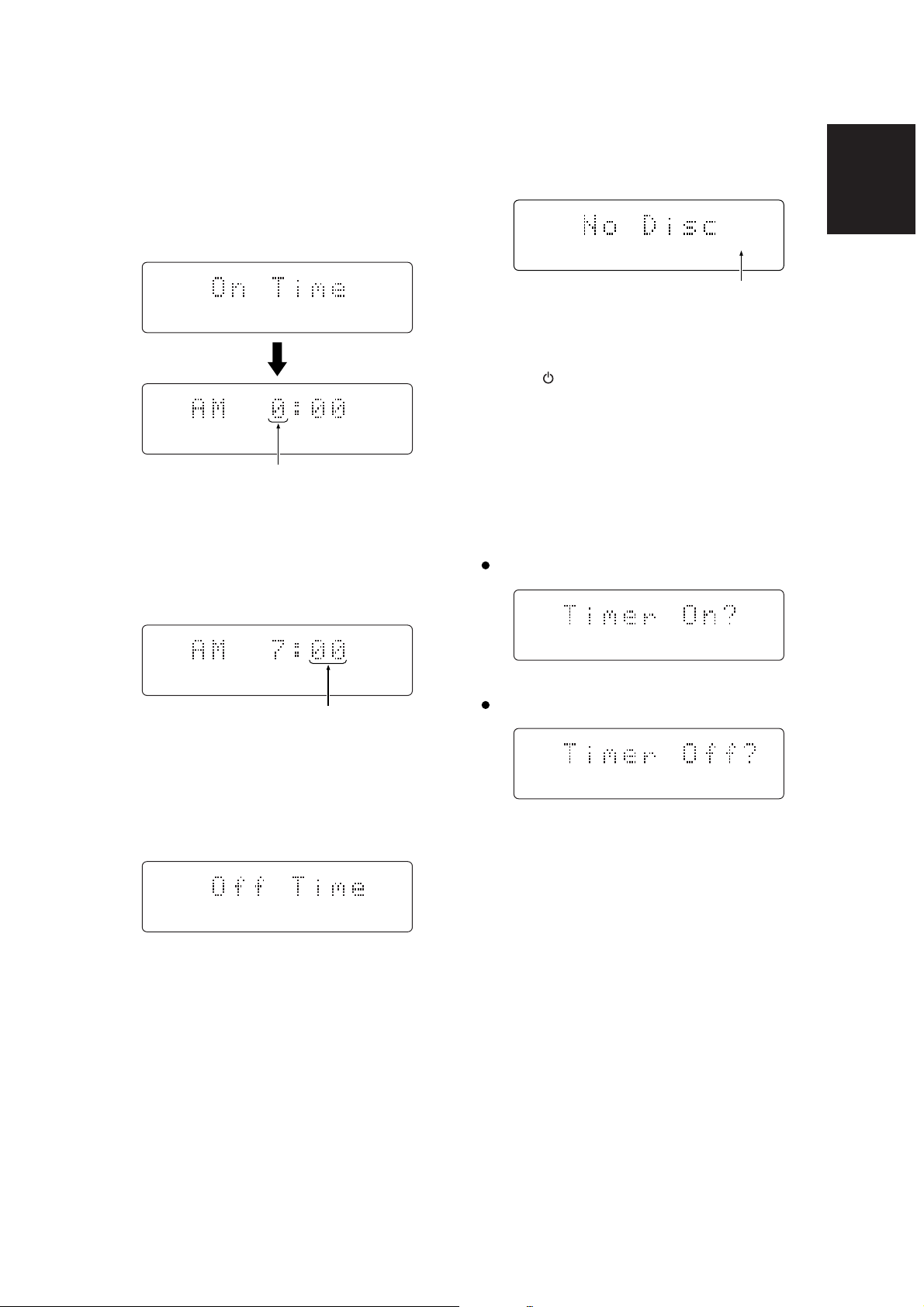
1. Press the TIMER button i on the remote control unit once.
On the display, "On Time" appears first followed by the
time, and the hour flashes. (Playback ON hour setting)
This flashes.
6. Next, the playback OFF time is set. Repeat steps 2
through 5 to set the hour and minute.
Upon completion of the settings, the timer setting mode is
cleared automatically.
ENGLISH
TIMER
This lights.
7. Press the 0 button n on the main unit to extend the disc
tray, place the disc on the tray, and close the tray.
8. Set the button q/z on the unit to off.
The button now lights up orange.
SETTING AND CLEARING TIMER PLAYBACK
1. Press the TIMER button i on the remote control unit
twice. "Timer Off" or "Timer On" appears on the display.
2. Set the playback ON hour using the 4 and ¢ buttons
!1 on the remote control unit or the 4/1 and ¡/¢
buttons , on the main unit.
3. Press the 7 button !2/x to enter the selection. The hour
input appears on the display, and the minute flashes.
(Playback ON minute setting)
This flashes.
4. Set the playback ON minute using the 4 and ¢ buttons
!1 on the remote control unit or the 4/1 and ¡/¢
buttons , on the main unit.
5. Press the 7 button !2/x to enter the selection.
On the display, "Off Time" appears first followed by the
time, and the hour flashes. (Playback OFF hour setting)
2. Switch from "Timer On" and "Timer Off" or vice versa using
the 4 and ¢ buttons !1 on the remote control unit or
the 4/1 and ¡/¢ buttons , on the main unit.
Select "Timer On" to set timer playback.
TIMER
Select "Timer Off" to clear timer playback.
3. Press the 7 button !2/x to enter the selection.
Important
Timer playback cannot be set if "No Disc", "Error Disc" or
"Blank Disc (CD-R(W))" is displayed.
13

CONCERNING MP3
ENGLISH
This unit is capable of playing MP3-CDs and CDR or CD-RW
discs with MP3 files created by the user.
For playing CDR or CD-RW discs with MP3 files, the ".mp3"
extension is used to save the data created by the user in files.
Other extensions such as ".doc," ".txt" and ".pdf" cannot be used.
This unit is not capable of digitally recording MP3 files.
MP3 PLAYBACK
1. Press the button q/z to switch on the power.
* The CD110's power will also be switched on if the SR110
is connected to the remote control jack and the SR110's
power is on.
2. Press the OPEN button b to open the panel.
3. Press the 0 button n.
The disc tray is now extended so place the disc on the tray
with its label surface facing up.
4. Press the 0 button n.
Alternatively, push the front of the disc tray gently.
5. Press the 6 button v on the main unit or the 3 button !0
on the remote control unit. Playback commences in
sequence from the first album. (See figure below)
Press the 3 button !0 again to play a track.
EXAMPLE OF PLAYBACK SEQUENCE
When there is just the one session
(Figure showing what is displayed by Windows Explorer)
SELECTING ALBUMS
1. Select the desired album using the 4/1 and ¡/¢
buttons , on the main unit or the 4 and ¢ buttons !1
on the remote control unit.
2. Press the 6 button v on the main unit or the 3 button !0
on the remote control unit. Playback now starts in sequence
starting from the selected album.
Press the 3 button !0 again to play a track.
CD-ROM drive Album 01
aaaa03.mp3
aaaa04.mp3
aaaa05.mp3
aaaa06.mp3
Album 02
bbbb07.mp3
bbbb08.mp3
Album 03
cccc09.mp3
cccc10.mp3
Skip
wwww.wav
xxxx.wav
AAAA01.mp3
BBBB02.mp3
The dotted lines ( ) with arrows indicate the MP3
album and track playback sequence.
Album 01 - album 07
In the example shown in the figure, the CD-ROM has seven
MP3 albums.
Root
14
"Dir" is displayed when using non-English characters.
Skip
yyyy.jpg
zzzz.doc
"File" is displayed when using non-English characters.
Album 04
eeee11.mp3
eeee12.mp3
Album 05
ffff13.mp3
ffff14.mp3
Album 06
gggg15.mp3
Playback up to 8 levels is possible.
AAAA01.mp3 - mmmm17.mp3
In the example shown in the figure, the CD-ROM has 17
tracks: "01" is the first track and "17" is the last one.
Only files with the ".mp3" extension are played: files with
extensions such as ".wav," ".jpg" and ".doc" are skipped.
Album 07
hhhh16.mp3
hhhh17.mp3

When there are multiple sessions
(Figure showing what is displayed by Windows Explorer)
"Dir" is displayed when using non-English characters.
CD-ROM drive Album 01
aaaa03.mp3
aaaa04.mp3
aaaa05.mp3
aaaa06.mp3
"File" is displayed when using non-English characters.
Album 02
bbbb07.mp3
bbbb08.mp3
Session 1
Album 03
cccc09.mp3
cccc10.mp3
Skip
wwww.wav
xxxx.wav
Album 04
Session 2
iiii11.mp3
iiii12.mp3
AAAA01.mp3
BBBB02.mp3
Root
Skip
yyyy.jpg
zzzz.doc
Album 05
eeee13.mp3
eeee14.mp3
Album 06
ffff15.mp3
ffff16.mp3
Album 07
gggg17.mp3
Album 08
jjjj18.mp3
jjjj19.mp3
Album 09
vvvv.zip
kkkk20.mp3
kkkk21.mp3
ENGLISH
Album 10
hhhh22.mp3
hhhh23.mp3
Album 11
llll24.mp3
llll25.mp3
Album 12
mmmm26.mp3
mmmm27.mp3
Even when there are multiple sessions, playback is still
performed in hierarchical sequence starting from the top
level.
The dotted lines with arrows ( ) indicate the MP3
album and track playback sequence.
Album 01 - album 012
In the example shown in the figure, the CD-ROM has twelve
MP3 albums.
Playback up to 8 levels is possible.
AAAA01.mp3 - mmmm27.mp3
In the example shown in the figure, the CD-ROM has 27
tracks: "01" is the first track and "27" is the last one.
Only files with the ".mp3" extension are played: files with
extensions such as ".wav," ".jpg" and ".doc" are skipped.
With the CD110 compact disc player, the playback sequence
may differ from the one displayed on the PC screen as shown
above. (It may also vary depending on the writing software
program.)
15

TROUBLESHOOTING
ENGLISH
If you believe that a malfunction has occurred, first check the
points listed below. The problem may have been caused by a
simple operational error or a connection problem. If the
problem is not solved even after carrying out the following
checks, consult your dealer or nearest Marantz sales office or
service center.
The disc fails to rotate.
- Has the power cord been connected correctly?
- Is the unit's power ON?
- Has the disc been placed in the correct position?
- Has the disc been placed upside down on the tray? (Is the
label side of the disc facing up?)
- Is the disc dirty?
- Is the disc scratched?
- Is the disc warped?
The disc rotates but no sound is heard.
- Have the amplifier and speaker been connected correctly?
- Is the amplifier's power ON?
- Has the amplifier's function or selector switch been set to
"CD" or "AUX" (to the position corresponding to where you
connected the CD110)?
- Is the amplifier's volume control at its lowest setting?
OPERATING PRECAUTIONS
In the winter you may notice that condensation forms on the
window of a well-heated room.
Condensation may also occur inside the CD player in the
following situations:
– When the listening room is first heated.
– When the humidity in the room is high.
– When the unit is moved from a cold environment to a warm
room.
If condensation occurs, the number of tracks cannot be read
and the CD player may not function properly. If this happens,
leave the power ON and wait for about 30 minutes before
operating the unit.
The CD player may interfere with the reception of your tuner
or TV set. If this occurs, place the CD player farther away
from the tuner or TV.
The CD player features very little noise compared to analog
records, and the noise before actual playback begins is
almost inaudible. Therefore, be careful not to set the volume
control of the amplifier too high, otherwise other audio
components such as the speakers may be damaged when
actual playback starts.
The disc stops rotating in mid-operation.
- Is the disc dirty?
- Is the disc scratched?
- Is the disc warped?
The sound breaks up or noise is heard.
- Is the disc dirty or scratched?
- Is the disc warped?
- Is the CD a music CD? (CD-ROMs for personal computers,
DTS-CDs, etc. cannot be played.)
Remote control operation is not possible.
- Is the transmitter of the remote control unit (RC110CD)
pointed correctly at the remote sensor of the CD player
(CD110)? Are there any obstacles between these two
windows?
- Have the batteries in the remote control unit (RC110CD)
run down?
- Is there another source of strong light striking the remote
sensor window of the CD player (CD110)?
- Is the REMOTE switch on the rear panel set to EXT.?
CD-R or CD-RW discs cannot be played.
- Has the disc been placed wrong side up on the tray?
- Has the finalizing work (TOC writing) been completed
correctly?
- Is the format (CD-DA) for music used for the recorded
information?
CLEANING OF EXTERIOR
SURFACES
With proper care and cleaning, the exterior finish of your
equipment will last indefinitely. Never use scouring pads, steel
wool, scouring powders or harsh chemical agents (e.g. lye
solution), alcohol, thinners,benzine, insecticide or other volatile
substances, as these will mar the finish of the cabinet.
Likewise, never use cloths containing chemical substances. If
the equipment becomes dirty, wipe the external surfaces with a
soft, lint-free cloth.
If the cabinet becomes heavily soiled:
– dilute some washing-up liquid in water, in a ratio of one part
detergent to six parts water;
– dip a soft, lint-free cloth in the solution and wring the cloth out
until it is damp;
– wipe the equipment with the damp cloth;
– dry the equipment by wiping it with a dry cloth.
REPAIRS
Only the most competent and qualified service technicians
should be allowed to service the equipment. The Marantz
company and its factory-trained warranty station personnel
have the knowledge and special facilities needed for the repair
and calibration of this precision equipment. After the warranty
period has expired, repairs will be performed for a charge if the
equipment can be restored to normal operation.
In the event of difficulty, consult your dealer or write directly to
the nearest location to you that is listed on the Marantz
Authorized Service Station list. Please quote the model and
serial number of the equipment and give a full description of
what you think is abnormal about the equipment’s behaviour.
16

TECHNICAL SPECIFICATIONS
AUDIO CHARACTERISTICS
Channels ................................................................................................................................................ 2 channels
Frequency range ..................................................................................................................................20Hz-20kHz
Dynamic range ............................................................................................................................................ > 90 dB
S/N ratio (WTD)..............................................................................................................................................87 dB
Channel separation (1 kHz) ........................................................................................................................... 87 dB
THD (1 kHz) ................................................................................................................................................. 0.02 %
Wow & flutter ..............................................................................................................................Precision of quartz
Error correction.................................................................................. Cross-interleave read solomon code (CIRC)
Analog output ......................................................................................................................................... 2.0 V RMS
Digital output (Coaxial) ................................................................................................................ 0.5 Vp-p/75 ohms
Digital output (Optical)................................................................................................................................-20 dBm
OPTICAL READOUT SYSTEM
Laser ...................................................................................................................................GaAIAs semiconductor
Wavelength ................................................................................................................................................. 780 nm
SIGNAL SYSTEM
Sampling frequency .................................................................................................................................. 44.1 kHz
Quantization ............................................................................................................................ 16-bit linear/channel
GENERAL
Power Supply .................................................................................................................................AC 120 V 60 Hz
Power Consumption ...................................................................................................................................... 0.16 A
Dimensions (W · H · D)..................................................... 8-1/4 · 2-3/4 · 12-3/16 inches (210 · 71.5 · 310 mm)
Net weight ....................................................................................................................................... 6.8 lbs (3.1 kg)
Operating temperatures ...................................................................................................................+5 ˚C ~ +45 ˚C
Operating humidity ..........................................................................................................5 % ~ 90 % (without dew)
ACCESSORIES
Remote control unit (RC110CD) ........................................................................................................................... 1
Dimensions (W · H · D) MAX ................................................ 2-1/2 · 7-3/4 · 1 inches (50.5 · 154.5 · 25 mm)
Weight.......................................................................................................................................... 0.13 lbs (60 g)
AA type Batteries .................................................................................................................................................. 2
Stereo audio cable ......................................................................................................................................... 1 pair
Remote cable ........................................................................................................................................................ 1
Warranty Card (USA) ............................................................................................................................................ 1
Warranty Card (CANADA)..................................................................................................................................... 1
User’s Guide.......................................................................................................................................................... 1
Specifications subject to change without prior notice.
1

COUNTRY COMPANY ADDRESS
ALGERIE Azur 2000 8, Lotissement Ben Hatadi, Alger, Algerie
ARMENIA NGYIG Ltd. 47 A/75 St. Lalaiants, 375000 Yerevan, Armenia
AUSTRALIA Jamo Australia Pty. Ltd., 24 Lionel Road, Mt. Waverley, VIC 3149, Australia
AUSTRIA Huber & Prohaska GmbH Taborstraße 95 / Ladestraße 1, Gebäude Hangartner, A-1200 Wien, Austria
BAHREIN Ambassador Stores P.O. Box 237,141, Government Avenue, Manama,Bahrein
BANGLADESH Target 1078, Ramjoy Mohanja Lane Asadgonj, Chittagong 4000, Bangladesh
BELGIUM Van der Heyden Audio N.V. Brusselbaan 278, 9320 Erembodegem, Belgium
BULGARIA Ariescommerce GmbH Makedonia Blvd. 16, 1606 Sofia, Bulgaria
CANADA Lenbrook Industries Limited 633 Granite Court, Pickering, Ontario
CHINA
CYPRUS Empire Hifi systems Ltd. P.O. Box 5604, Nicosia, Cyprus
CZECH REPUBLIC Audio International Sokolska 41, 67902 Rajecko, OKR,Blansko, Czech Republic
DENMARK Audio Nord Dali Allé 1, 9610 Noerager, Denmark
DUBAI V.V.& SONS P.O. Box 105, Dubai, U.A.E.
EGYPT Solimco 9, El Attibaa St. Doki, Cairo, Egypt
ESTONIA HiFi Club Estonia Ehte 4, 90503 Haapsalu, Estonia
F.Y.R.O.M. T.P. KODI ul.Cedomir Kantargiev 21a, Skopje, Former Yugoslavian Republic of Macedonija
FINLAND Audio Nord Uudenmaankatu 4-6, Helsinki SF-00120, Finland
FRANCE Marantz France A division of Marantz Europe B.V., P.O. Box 301, 92 156 Suresnes Cedex, France
GERMANY Marantz Deutschland Hakenbusch 3, 49078 Osnabrück, Germany
GREECE Adamco S.A. 188, Hippocratous Street, 11471 Athens, Greece
HEADQUARTERS EUROPE: Marantz Europe B.V. Building SFF-2, P.O. Box 80002, 5600 JB Eindhoven, The Netherlands
HONG KONG Marantz Asia Ltd. Unit 1706, Metroplaza II, 223 Hing Fong Road, Kwai Fong, N.T., Kowloon, Hong Kong
HUNGARY Infovox Ltd. Terez Krt.31, 1067 Budapest, Hungary
ICELAND ID Electronics Ltd. Armula 38, 108 Reykjavik, Iceland
INDIA NOVA Audio Private 8,Punam Co-op.Society 29/30 Road#5, Union Park MUMBAI 400052, India
IRAN Home Co. 5th floor no 878 Philips Building Enghelab ave, P.O. 11365/7844 Tehran, Iran
IRELAND Marantz Ireland Clonskeagh, Dublin 14, Ireland
ISRAEL Elmor Ltd. 52 Heh Beiyar Street, Kikar Hamedina, Tel Aviv, Israel
ITALY Marantz Italy
IVORY COAST Hifivoir B.P. 2428, Abidjan 01, Ivory Coast
JAPAN Marantz Japan Inc. 35-1 Sagami Ohno 7-Chome, Sagamihara-shi, Kanagawa 228-8505, Japan
KOREA Mk Enterprises Ltd. 121-210, 2F Shinhan Bldg., 247-17 Seokyo-dong, Mapo-ku, Seoul, Korea
KUWAIT alAlamiah Electronics Intl. P.O. Box 8196, Salmiah 22052, Kuwait
LATVIA Ace Ltd. 61, LacPlesa Str., Riga LV 1011, Latvia
LEBANON AZ Electronics S.A., 1, P.O. Box 11 2833, Beirut, Lebanon
LITHUANIA Accapella Ltd. Ausros, Vartu G/5, Pasazo SKG., 2001 Vilnius, Lithuania
MALAYSIA Wo Kee Hong Electronics Sdn. Bhd.
MALTA Doneo Co Ltd. 78 The Strand, Sliema SLM07, Malta
MAURITIUS SKR Electronics Ltd. P.O. Box 685, Bell Village, Port Louis, Mauritius
MILITARY MARKET EUROPE PASCO GmbH PO BOX 1280, Sandhausen 69200, Germany
NETHERLANDS Marantz Domestic Sales
NEW ZEALAND Wildash Audio Systems 14 Malvern Road, Mt. Albert, Auckland, New Zealand
NORWAY Audio Nord Sandkerveien 64, Oslo 0483, Norway
OMAN Mustafa & Jawad Trading CO. P.O. Box 1918, Ruwi, Oman
POLAND Philips Polska Sp. z.o.o. Al.Jerozolimskie 195b, 02 222 Warszawa, Poland
PORTUGAL Corel2 Comércio de Electrónica Lda., Av. Luís Bívar, No 85 A, 1050 Lisboa, Portugal
PROFESSIONAL EUROPE Marantz Professional Products
PROFESSIONAL U.S.A. Marantz Professional Products
QATAR Almana & Partners W.W.L. P.O. Box 49, Doha, Qatar
REUNION Vision + 180 Rue du Marechal Leclerc, 97400 Saint Denis, Ile de la Reunion
ROMANIA Nova Music Entertainment 5, Zagazului Str. Bl.1G,apt.18, sector 1,Bucharest, Romania
RUSSIA Absolute Audio 7/2, Montazhnaya Street, 107497 Moscow, Russia
SAUDI ARABIA Adawlia Univ. Electr. Apl P.O. Box 2154, Alkhobar 31952, Saudi Arabia
SINGAPORE Forward Marketing (S) Pte. Ltd. Wo Kee Hong Centre, 29 Leng Kee Road, Singapore 159099, Singapore
SLOVAKIA Bis Audio s.r.o. Nam. SNP 10, 96001 Zvolem, Slovakia
SLOVENIA Bofex Smartinska 152, HALA V/3, 61000 Ljubljana, Slovenia
SOUTH AFRICA Coherent Imports (PTY) Ltd. P.O. Box 1614, Alberton, 1450, South Africa
SPAIN Marantz Spain Martinez Villergas 2, Apartado 2065, Madrid 28027, Spain
SRI LANKA The listening Room Mezzanine Floor, The Landmark 385, Galle Road, Colombo - 3, Sri Lanka
SWEDEN Audio Nord Almedalsvagen 4, Gotenborg 402-23, Sweden
SWITZERLAND Sound Company AG Postfach, 8010 Zürich, Switzerland
SYRIA Hamzeh & Partners Hafez Ibrahim Str. No 117, Damascus Shalan, Syria
TAHITI Covecolor Av. Prince Hinoi, Cours de l'union sacré, P.O. Box 2334, Papeete, Tahiti
TAIWAN Pai-Yuing Co. Ltd. 6th No 148 Sung Kiang Road, Taipei 10429, Taiwan R.O.C.
THAILAND MRZ Standard Co. Ltd. 746-750 Mahachai Road, Wangburapa, Bangkok 10200, Thailand
TUNESIA Societe EDEVIG 40, Avenue du Golfe Arabe, El Menzah, 1004, Tunesia
TURKEY Türk Philips Ticaret A.S.
U.K. Marantz Hifi UK Ltd.
U.S.A. Marantz America Inc. 440 Medinah Road, Roselle, IL 60172, U.S.A.
YUGOSLAVIA ITM Company Omladinskih Brigada 86, 11070 Belgrade, Yugoslavia
EXPORT Marantz Domestic Sales
www.marantz.com
Guang Chang Audio International Co., Ltd.
No.38 Yushan Road, ShiQiao, Pan Yu, Guang Dong, China
Via Casati 23, 20052 Monza (Milano), Italy, Servizio Consumatori 1678-20026, Numero Verde
102 Jalan SS 21/35, Damansara Utama, 47400 Petaling Jaya, Selangordarul Ehsan, Malaysia
A division of Marantz Europe B.V., Building SFF2, P.O. Box 80002, 5600 JB Eindhoven, The Netherlands
Kingsbridge House, Padbury Oaks, 575-583 Bath Road, Longford, Middlesex UB7 0EH, U.K.
Distributed by: Superscope Technologies Inc., 1000 Corporate Blvd. Ste.D, Aurora, Illino
Yukari Dudullu Organize sanayi Bolgesi, 2.Cadde no.28, 81260 Umraniye-Istanbul, Turkey
Kingsbridge House, Padbury Oaks, 575-583 Bath Road, Longford, Middlesex UB7 0EH, U.K.
A division of Marantz Europe BV,Building SFF2, P.O. Box 80002, 5600 JB Eindhoven, The Netherlands
R
is a registered trademark.
Printed in China 04/2001 MITs 324W851250

Model SR110 User Guide
Receiver
R

CAUTION
RISK OF ELECTRIC SHOCK
DO NOT OPEN
CAUTION: TO REDUCE THE RISK OF ELECTRIC SHOCK,
DO NOT REMOVE COVER (OR BACK)
NO USER-SERVICEABLE PARTS INSIDE
REFER SERVICING TO QUALIFIED SERVICE PERSONNEL
The lightning flash with arrowhead symbol, within an
equilateral triangle, is intended to alert the user to the
presence of uninsulated “dangerous voltage” within the
product’s enclosure that may be of suffi-cient magnitude
to constitute a risk of electric shock to persons.
The exclamation point within an equilateral triangle is
intended to alert the user to the presence of important
operating and maintenance (servicing) instructions in the
literature accompanying the appliance.
WARNING
TO REDUCE THE RISK OF FIRE OR ELECTRIC SHOCK,
DO NOT EXPOSE THIS APPLIANCE TO RAIN OR MOISTURE.
CAUTION:
TO PREVENT ELECTRIC SHOCK, MATCH WIDE BLADE OF
PLUG TO WIDE SLOT, FULLY INSERT.
ATTENTION:
POUR ÉVITER LES CHOCS ÉLECTRIQUES,
INTRODUIRE LA LAME LA PLUS LARGE DE LA FICHE DANS LA
BORNE CORRESPONDANTE DE LA PRISE ET POUSSER
JUSQU’AU FOND.
NOTE TO CATV SYSTEM INSTALLER:
This reminder is provided to call the CATV (Cable-TV) system installer’s attention to Article 820-40 of the NEC, that
provides guidelines for proper grounding and, in particular, specified that the cable ground shall be connected to the
grounding system of the building, as close to the point of cable entry as practical.
NOTE:
This equipment has been tested and found to comply
with the limits for a Class B digital device, pursuant to
Part 15 of the FCC Rules. These limits are designed
to provide reasonable protection against harmful
interference in a residential installation. This
equipment generates, uses and can radiate radio
frequency energy and, if not installed and used in
accordance with the instructions, may cause harmful
interference to radio communications. However, there
is no guarantee that interference will not occur in a
particular installation. If this equipment does cause
harmful interference to radio or television reception,
which can be determined by tuning the equipment off
and on, the user is encouraged to try to correct the
interference by one or more of the following
measures:
- Reorient or relocate the receiving antenna.
- Increase the separation between the equipment and
receiver.
- Connect the equipment into an outlet on a circuit
different from that to which the receiver is connected.
- Consult the dealer or an experienced radio/TV
technician for help.
NOTE:
Changes or modifications may cause this unit to fail
to comply with Part 15 of the FCC Rules and may

IMPORTANT SAFETY
INSTRUCTIONS
READ BEFORE OPERATING EQUIPMENT
This product was designed and manufactured to meet strict
quality and safety standards. There are, however, some installation and operation precautions which you should be particularly
aware of.
1. Read Instructions - All the safety and operating instructions
should be read before the appliance is operated.
2. Retain Instructions-The safety and operating instructions
should be retained for future reference.
3. Heed Warnings-All warnings on the appliance and in the
operating instructions should be adhered to.
4. Follow Instructions-All operating and use instructions
should be followed.
5. Cleaning-Unplug this video product from the wall outlet
before cleaning. Do not use liquid cleaners or aerosol
cleaners. Use a damp cloth for cleaning.
6. Attachments-Do not use attachments not recommended
by the video product manufacturer as they may cause
hazards.
7. Water and Moisture-Do not use this video product near
water-for example, near a bath tub, wash bowl, kitchen
sink, or laundry tub, in a wet basement, or near a swimming
pool, and the like.
8. Accessories-Do not place this video product on an
unstable cart, stand, tripod, bracket, or table. The video
product may fall, causing serious injury to a child or adult,
and serious damage to the appliance. Use only with a cart,
stand, tripod, bracket, or table recommended by the
manufacturer, or sold with the video product. Any mounting
of the appliance should follow the manufacturer’s
instructions, and should use a mounting accessory
recommended by the manufacturer.
9. Ventilation-Slots and openings in the cabinet are provided
for ventilation and to ensure reliable operation of the video
product and to protect it from overheating, and these
openings must not be blocked or covered. The openings
should never be blocked by placing the video product on a
bed, sofa, rug, or other similar surface. This video product
should never be placed near or over a radiator or heat
register. This video product should not be placed in a builtin installation such as a bookcase or rack unless proper
ventilation is provided or the manufacturer’s instructions
have been adhered to.
10. Power Sources-This video product should be operated
only from the type of power source indicated on the
marking label. If you are not sure of the type of power
supply to your home, consult your appliance dealer or local
power company. For video products intended to operate
from battery power, or other sources, refer to the operating
instructions.
11. Grounding or Polarization-This video product is equipped
with a polarized alternating-current line plug (a plug having
one blade wider than the other). This plug will fit into the
power outlet only one way. This is a safety feature. If you
are unable to insert the plug fully into the outlet, try
reversing the plug. If the plug should still fail to fit, contact
your electrician to replace your obsolete outlet. Do not
defeat the safety purpose of the polarized plug.
AC POLARIZED PLUG
12. Power-Cord Protection-Power-supply cords should be
routed so that they are not likely to be walked on or pinched
by items placed upon or against them, paying particular
attention to cords at plugs, convenience receptacles, and
the point where they exit from the appliance.
13. Protective Attachment Plug - The appliance is equipped
with an attachment plug having overload protection. This is
a safety feature. See Instruction Manual for replacement or
resetting of protective device. If replacement of the plug is
required, be sure the service technician has used a
replacement plug specified by the manufacturer that has
the same overload protection as the original plug.
14. Outdoor Antenna Grounding-If an outside antenna or cable
system is connected to the video product, be sure the
antenna or cable system is grounded so as to provide some
protection against voltage surges and built up static charges.
Section 810 of the National Electrical Code, ANSI/NFPA No.
70-1984, provides information with respect to proper
grounding of the mast and supporting structure, grounding
of the lead-in wire to an antenna discharge unit, size of
grounding conductors, location of antenna-discharge unit,
connection to grounding electrodes, and requirements for
the grounding electrode. See Figure 1.
15. Lightning-For added protection for this video product
receiver during a lightning storm, or when it is left unattended and unused for long periods of time, unplug it
from the wall outlet and disconnect the antenna or cable
system. This will prevent damage to the video product due
to lightning and power-line surges.
16. Power Lines-An outside antenna system should not be
located in the vicinity of overhead power lines or other electric
light or power circuits, or where it can fall into such power lines
or circuits. When installing an outside antenna system,
extreme care should be taken to keep from touching such
power lines or circuits as contact with them might be fatal.
17. Overloading-Do not overload wall outlets and extension
cords as this can result in a risk of fire or electric shock.
i

18. Object and Liquid Entry-Never push objects of any kind into
this video product through openings as they may touch
dangerous voltage points or short-out parts that could
result in a fire or electric shock. Never spill liquid of any kind
on the video product.
19. Servicing-Do not attempt to service this video product
yourself as opening or removing covers may expose you to
dangerous voltage or other hazards. Refer all servicing to
qualified service personnel.
20. Damage Requiring Service-Unplug this video product from
the wall outlet and refer servicing to qualified service
personnel under the following conditions:
a. When the power-supply cord or plug is damaged.
b. If liquid has been spilled, or objects have fallen into the
video product.
c. If the video product has been exposed to rain or water.
d. If the video product does not operate normally by following
the operating instructions. Adjust only those controls that
are covered by the operating instructions as an improper
adjustment of other controls may result in damage and will
often require extensive work by a qualified technician to
restore the video product to its normal operation.
e. If the video product has been dropped or the cabinet has
been damaged.
FIGURE 1
EXAMPLE OF ANTENNA GROUNDING ACCORDING TO
NATIONAL ELECTRICAL CODE INSTRUCTIONS
CONTAINED IN ARTICLE 810 - “RADIO AND TELEVISION EQUIPMENT”
f. When the video product exhibits a distinct change in
performance-this indicates a need for service.
21. Replacement Parts-When replacement parts are required,
be sure the service technician has used replacement parts
specified by the manufacturer or have the same
characteristics as the original part. Unauthorized
substitutions may result in fire, electric shock or other
hazards.
22. Safety Check-Upon completion of any service or repairs to
this video product, ask the service technician to perform
safety checks to determine that the video product is in
proper operating condition.
23. Carts and Stands-The appliance should be used only with
a cart or stand that is recommended by the manufacturer.
24. An appliance and cart combination should be moved with
care. Quick stops, excessive force, and uneven surfaces
may cause the appliance and cart combination to overturn.
GROUND
CLAMP
ELECTRIC
SERVICE
EQUIPMENT
NEC - NATIONAL ELECTRICAL CODE
This Class B digital apparatus meets all requirements of the
Canadian Interference - Cansing Equipment Regulations.
ANTENNA
LEAD IN
WIRE
ANTENNA
DISCHARGE UNIT
(NEC SECTION 810-20)
GROUNDING CONDUCTORS
(NEC SECTION 810-21)
GROUND CLAMPS
POWER SERVICE GROUNDING
ELECTRODE SYSTEM
(NEC ART 250, PART H)
Cet appareil numérique de la Classe B respecte toutes les
exigences du Règlement sur le matériel brouilleur du Canada.
ii
1
2 3 4 5
STANDBY DISPLAY MUTE OPEN
10
13
19
11
16
20
AUX
FM/AM
CD CDR MD
1
2
SR110
6
3
87
5
RANDOM REPEAT
7
CDR
NEWS/TAF/P
VOLUME
4
6
STANDBY DISPLAY MUTE OPEN
8
9 10 11 12 13
AMP
BAND
9
MEMO
WOW
DISPLAY ENTER TIMER SLEEP
12
WOWMUTE
14
15
PHONES
TUNER
TIMER
14
VOLUME
+
17
SYSTEM REMOTE CONTROLLER
RC110SR
18
ANTENNA
LEFT
RIGHT
15 16 17
)
AM
FM (75
Ω
IN IN
AUXCD CDR
OUT OUT
MD
REMOTE CONTROL
MODEL NO. SR110
SPEAKER
RIGHT
SYSTEM
LEFT
IN
SELECTOR
SYSTEM
INT.
OUT
A B C D E F G IH
iii

FOREWORD
This section must be read before any connection is made to the
mains supply.
WARNINGS
Do not expose the equipment to rain or moisture.
Do not remove the cover from the equipment.
Do not push anything inside the equipment through the
ventilation holes.
Do not handle the mains lead with wet hands.
FEATURES
Easy operation with remote control bus in SYSTEM mode
operation
High power output of the discrete configuration possesses a
high level of reliability.
30-Station random preset tuner
System operation switch
This unit can be operated as a system component in
combination with the CD, CD-R and MD players from the
Marantz AV system.
Program Timer/Sleep Timer
ENGLISH
EQUIPMENT MAINS WORKING SETTING
Your Marantz product has been prepared to comply with the
household power and safety requirements that exist in your
area.
SR110 can be powered by 120 V AC only.
PRECAUTIONS
The following precautions should be taken when operating the
equipment.
GENERAL PRECAUTIONS
When siting the equipment ensure that:
— the ventilation holes are not covered;
— air is allowed to circulate freely around the equipment
— it is on a vibration free-surface;
— it will not be exposed to interference from an external
source;
— it will not be exposed to excessive heat, cold, moisture or
dust;
— it will not be exposed to direct sunlight;
— it will not be exposed to electrostatic discharges
Never place heavy objects on the equipment.
If a foreign body or water does enter the equipment, contact
your nearest dealer or service centre.
Do not pull out the plug by pulling on the mains lead, hold the
plug.
It is advisable when leaving the house, or during a thunderstorm,
to disconnect the equipment from the mains supply.
ABOUT THE WOW
WOW is a proprietary new algorithm from SRS Labs, which
processes a stereo signal to provide extraordinary
enhancement to the listening experience. Ordinary stereo
present a rather limited spatial presentation, and often lackluster bass (low frequency) performance. Any sound system
including smaller multimedia speakers, headphones, mini
stereos, portable “boom boxes” or televisions can deliver an
audio performance with dramatically improved image size,
dynamics and immersion when playing a signal processed with
WOW. The procession of the spatial cues surrounds the
listener with a holographic representation of the performance.
In addition, TruBass builds upon WOW by providing bass that is
deep, rich and controlled, through means that don’t require a
large speaker or cabinet.
1

CONTROL BUTTON ON THE
ENGLISH
REMOTE CONTROL UNIT
q Power switch
Press this switch to turn the power of the unit ON. If components
of Marantz AV system are connected through the REMOTE
CONTROL bus, this will turn these components ON. Press this
switch again to turn the unit OFF, and the unit enters standby
mode.
w Function buttons
There are FM/AM, CD, CD-R, MD and AUX buttons. These
buttons are used to select the source to be played or recorded.
To switch the input selector of the receiver, press the button.
Function button control Source to be played
on the remote
FM/AM FM or AM
CD CD player (CD110)
CD-R CD Recorder
MD MD deck
AUX AUX (TV game, etc.)
e Numeric (ten keypad) button
These buttons are used to select the preset memory when FM/
AM function is selected.
These buttons are used to enter the track or program number
when CD or CD-R function is selected.
r NEWS/TA / REPEAT button
This button is used to repeat the disc, tracks or programme when
CD, CD-R or MD function is selected.
t F/P / RANDOM button
This button is used to display the frequency or preset channel.
This button is used to random play when CD, CD-R or MD function
is selected.
yu – VOLUME + button
These buttons are used to change the volume for listening.
Press the + button to increase and the – button to decrease the
volume.
i 3 (Play) button
This button is unavailable when FM/AM function is selected.
This button is used to play the source disc when CD, CD-R or MD
function is selected.
o ¢ button
This button is used to increase the number on the tuner preset
memory or advance to next track on CD, CD-R or MD.
!0 4 button
This button is used to decrease the number on the tuner preset
memory or return to previous tracks on CD, CD-R or MD.
!2 ¡ button
This button is used to increase the frequency when FM/AM
function is selected.
This button is used to search forward when CD, CD-R or MD
function is selected.
!3 1 button
This button is used to decrease the frequency when FM/AM
function is selected.
This button is used to search backward when CD, CD-R or MD
function is selected.
!4 8 (Pause) button
This button is unavailable when FM/AM function is selected.
This button is used to interrupt the source disc playing/recording
when CD, CD-R or MD function is selected.
!5 WOW button
This button is used to change the WOW function level.
Each press of this button change the WOW function level following
order.
OFF → LOW → HIGH → OFF
Note:
When this button is pressed, the sound of speakers is muted
momentary. This is not malfunction.
!6 MUTE button
This button is used to mute the sound from the speakers. When
this button is pressed, the speakers’ sound level is muted and
“MUTE” appears on the display. Pressing this button again cancels
the muting function, and it can also be cancelled by pressing one
of the function buttons.
!7 SLEEP timer button
This button is used to set the sleep timer. Each press of this
button change the sleep time following order.
10 → 20 → 30 → 60 → 90 → OFF (original display)
The display is dimmed when the sleep timer is set. The setting
time passes, the power is turned off.
!8 TIMER program button
This button is used to activate the timer program.
!9 DISPLAY button
This button is used to change the display information (source,
and present time) or brightness.
Note:
A present time can be displayed when the FM/AM function is
set with function button. A present time can be also
displayed for 10 seconds in standby mode when the FM/AM
function is set with function button.
@0 ENTER button
This button is used to decide for the receiver’s JOG control.
!1 7 (Stop) button
This button is unavailable when FM/AM function is selected.
This button is used to stop the source disc playing/recording when
CD, CD-R or MD function is selected.
2

OPERATION OF REMOTE CONTROL UNIT
1. REMOTE CONTROL
The distance between the transmitter of the remote control unit
and the IR SENSOR of the SR110 should be less than about 5
meters. If the transmitter is pointed to a direction other than the
IR SENSOR or if there is an obstacle between them, remote
control may not be possible.
Remote-controllable range
Approx 5 meters
60°
2. LOADING BATTERIES
The life of the batteries used with the remote control unit is
about 6 months with normal use. Also be sure to replace
batteries earlier when you notice that they are getting weak.
ENGLISH
1. Remove the back cover.
2. Insert the new batteries (AA type) with correct (+) and (–)
polarity.
3. Close until it clicks.
3

CONNECTORS AND CONTROLS
ENGLISH
ON THE MAIN UNIT
A Terminal for FM antenna, 75 ohms
For connecting an external FM antenna with a circular plug, or for
connecting a cable network.
z STANDBY/power switch and
indicator
Press to turn power ON and press again to switch to STANDBY
mode. The indicator lights GREEN when power is ON, and lights
RED when in STANDBY mode. The indicator lights AMBER when
the timer program is set during STANDBY mode.
Terminals for AM antenna and
Grounding
To connect the supplied AM loop antenna, use the terminals
marked “AM” and “GND”.
In areas where the AM loop antenna gives unsatisfactory results,
it is recommended that the receiver be connected to an outdoor
antenna. Use the terminal marked ‘AM’ for this. A grounding lead
can be connected to the terminal marked ‘GND’ to further reduce
interference. In this case, it must be connected together with the
supplied loop antenna.
B CD input jacks
Connect to the audio output jacks of a CD player.
C AUX input jacks
Connect to the audio output jacks of the TV set, DVD player, etc.
D CD-R input/output jacks
Connect the IN jacks to the output jacks of a CD-R player, and
the OUT jacks to its input jacks.
E MD input/output jacks
Connect the IN jacks to the output jacks of a MD player, and the
OUT jacks to its input jacks.
F REMOTE CONTROL jacks
Connect to a component equipped with remote control jacks.
(Refer to page 3.)
x DISPLAY button
This button is used to change the display for information such as
clock time.
A present time can be displayed for 10 seconds in standby mode
by pressing this button.
The brightness of the display can be changed to dimmer or normal
by pressing this button.
c MUTE button
This button is used to mute the sound from the speakers. When
this button is pressed, the speakers’ sound level is muted and
“MUTE” appears on the display. Pressing this button again cancels
the muting function, and it can also be cancelled by pressing one
of the function buttons.
v Door OPEN button
This button is used to open the door.
b Front panel door
This door be opened by pressing the door OPEN button.
n IR lens
You can operate the unit even if the receiver door is closed. The
infrared signal from the remote control enters the unit through
this lens and infrared sensor.
Note:
Never remove this lens. If you remove this lens, the receiver
cannot receive the infrared signal from remote control when
the SR110’s door is closed.
G System control switch
This switch selects the system operation mode. Set to SYSTEM
position when the unit is being used in combination with a CD
(CD110). If your component is not capable of system connection,
set this switch to INT position.
H AC power cord
Plug into an AC 120V household outlet.
I SPEAKER terminals
Connect the left and right speaker leads, observing the + and –
polarity of the leads and terminals.
4
m JOG control
The JOG control can be used in the AMP, TUNER and TIMER
modes. Details of operation are as follows:
AMP mode: Source select (Usual setting)
Balance control (AMP button is pressed twice)
Treble control (AMP button is pressed three
times)
Bass control (AMP button is pressed four times)
(When the AMP button is pressed once, volume
control mode is set for volume control knob.)
TUNER mode: Frequency scan mode (last operation is
memorised)
Preset memory mode (last operation is
memorised)
Auto, Mono selecting Mode
TIMER mode: Program and confirm timer setting
For more detail, refer to the respective page.

, AMP button
The JOG control can be used in the TUNER, AMP or TIMER
modes. Press to change the mode of JOG control to AMP mode.
5 seconds after the previous JOG operation is finished, the mode
of JOG control will return to AMP mode automatically. You can
also use this button to return to AMP mode immediately. The
function of JOG control in AMP mode is changed as follows (except
the volume adjust mode):
SOURCE select mode: To select input mode.
(Volume adjust mode: To adjust the volume level by turning
the volume control.)
Balance control mode: To adjust the speaker balance.
BASS control mode: Tone control (Low frequency)
TREBLE control mode: Tone control (High frequency)
The AMP mode is used for tone control (BASS/TREBLE) and to
change also source for JOG control.
. TUNER button
Press to select FM or AM tuner when another source is selected
and select the JOG operation for TUNER selection. Use this button
to select the JOG operation for a scan of frequency or preset
memory mode. The TUNER button changes modes as below.
FREQUENCY mode: To scan tuning by frequency by JOG
control.
PRESET mode: To scan tunings in the preset memory by
JOG control.
TUNER mode: To change FM broadcasting to MONO or
STEREO.
The “MONO” indicator lights up on the
display in MONO position, the “AUTO”
indicator lights up when there is no signal
and “STEREO” lights up when a stereo
signal is received.
Please refer to page 9 for tuner operations.
⁄5 PHONES jack
For connecting a pair of stereo headphones. When the
headphones are connected to this jack, the speaker sound is
turned off.
Note:
Door cannot be closed when headphones connected.
⁄6 Display panel
This panel shows information on the status of the unit.
⁄7 Infrared sensor
The infrared signal from the remote control enters the unit through
this sensor.
ENGLISH
⁄0 TIMER button
This button is used to program and check the timer program.
Please refer to page 11 for timer program operation.
⁄1 BAND button
This button is used to change the reception band to FM or AM.
⁄2 MEMO button
This button is used to set the preset memory of the tuner or clock
time.
Please refer to the tuner and timer operations.
⁄3 WOW button
This button is used to change the WOW function level.
Each press of this button change the WOW function level following
order.
OFF → LOW → HIGH → OFF
Note:
When this button is pressed, the sound of speakers is muted
momentary. This is not malfunction.
⁄4 VOLUME control
To increase or decrease sound level. To increase the sound level
turn clockwise, and to decrease turn counter-clockwise.
5

CONNECTIONS
ENGLISH
SYSTEM CONNECTION
FEATURES OF SYSTEM CONNECTION
Synchronized power ON/OFF
By switching the power switch q/z, you can turn the CD
player, CD Recorder and MD deck connected through the
REMOTE CONTROL bus connection ON or OFF.
You cannot turn on and off by pressing the power switch of
connected components.
Auto source selection
When the CD in the CD110 starts playing by pressing the
play button on the CD110, the SR110 receiver will change
source automatically.
CONNECT TO SYSTEM CONNECTION
This unit is equipped with the remote control bus function.
Connecting it to Marantz AV system components equipped with
REMOTE CONTROL jacks, such as a CD player (CD110),
means that these components can be remote controlled from
this unit (SR110).
Connect the REMOTE CONTROL jacks of this unit to the
REMOTE CONTROL jacks of another component using RCAtype pin lead provided.
To operate the SR110 in the SYSTEM mode, the leads from the
other components must be connected to the SR110.
The lead from OUTPUT terminal of other component is
connected to INPUT terminal of the SR110.
Set the REMOTE CONTROL selector of this unit (SR110) to
SYSTEM position. Set the REMOTE CONTROL selector of
connected components to EXT position.
Note:
– Plug into AC outlet after all connections are finished.
– When connecting the supplied audio cable, confirm the
red plugs are connected to R jacks and the white plugs
are connected to L jacks.
We recommend you use to supplied audio cable.
– When using the supplied digital optical cable, remove the
dust cover.
– Attach the dust cover to prevent dust when removing the
digital optical cable.
– When connecting the digital optical cable, make sure it is
fully inserted.
SYSTEM OPERATION
The remote control system can be used to control Marantz
system components equipped with REMOTE CONTROL (Bus)
jacks and SYSTEM (Bus) jacks, such as CD110. An example
procedure for system operation is described below. Here, we
take as an example the connection of a CD player (CD110) to
this receiver (SR110) through the REMOTE CONTROL jacks.
(The numbers of controls and buttons on the main unit are
enclosed in , and those on the remote control are enclosed in
.)
1. Press the power switch q/z to turn the receiver power
ON.
2. All the components connected to the REMOTE CONTROL
jacks are turned ON.
3. Press the CD button w to select CD player as a source
and set the remote control to CD mode.
4. Press the “5” of the numeric button e to select track
number 5 of the CD.
5. The CD player (CD110) starts to play the CD.
6. Press the VOLUME buttons yu or turn the VOLUME
control ⁄4 to adjust the listening volume.
7. Press the 7 !1 button to stop the CD.
8. Press the power switch q/z to turn the power off and into
the standby mode.
The SR110 receiver and all the components connected to it
are turned OFF.
NO SYSTEM CONNECTION
You can use connected components as a single unit by setting
the system control switch to INT position.
When you use this unit in combination with other Marantz
components for which a system connections is not possible, or
components of other brands, you can use them independently
by setting the system control switch to INT position.
NOTE OF SPEAKER CABLE
When connecting the speaker cable, you use the cable as
following figures;
IMPORTANT
– When the system connection is setup, SR110 and CD110
should be stacked as following figures.
SR110
STANDBYDISPLAY MUTE OPEN
STANDBY OPEN
6
SR110
CD110
CD110
0.6 mm -1.5 mm
Never use the cable as following figures. If you use the
following cable, the speaker terminal may be damaged.
x mm >1.5 mm

ENGLISH
FM EXTERNAL ANTENNAFM FEEDER ANTENNA
F-type (for U version) / IEC type (for N version)
converter plug (attached)
When using the FM antenna
attach to this apparatus
)
ANTENNA
LEFT
RIGHT
FM (75
Ω
IN IN
AUXCD CDR
AMGND
OUT OUT
MD
REMOTE CONTROL
IN
OUT
AM LOOP ANTENNA
MODEL NO. SR110
SPEAKER
SYSTEM
SELECTOR
SYSTEM
INT.
RIGHT
LEFT
SPEAKER SYSTEM
(L)
(R)
ANALOG OUT
LEFT
RIGHT OUT
REMOTE CONTROL
IN
REMOTE
CONTROL
SELECTOR
COAX.––OPT.
EXT.
INT.
DIGITAL OUT
MODEL NO. CD110
7

BASIC OPERATIONS
ENGLISH
NORMAL PLAY
1. Press the power switch q/z to turn the power ON.
2. Press the optimum function button w or turn JOG control
m in the SOURCE select mode to select the source to be
played. Please refer to the next table.
Function button control Source to be played
on the remote
FM/AM FM or AM
CD CD player (CD110)
CDR CD recorder
MD MD deck
AUX AUX (TV game, etc.)
3. Start playing the source component. Adjust the listening
volume with the VOLUME control ⁄4 or VOLUME buttons
yu.
The source selector will change players automatically in
SYSTEM mode.
TO ADJUST BALANCE
The speaker balance can be changed by JOG control.
1. Press the AMP button , twice to set the mode of the JOG
control m to BALANCE mode.
“BAL” is displayed.
TO ADJUST TONE CONTROL (BASS AND TREBLE)
The Bass and Treble frequencies can be controlled by JOG
control.
1. Press the AMP button , three or four times to set the mode
of JOG control m to TONE control mode. “TRE” or “BASS” is
displayed.
2. Within approx. 5 seconds, turn the JOG control m to the
left to decrease, or to the right to increase step by step.
You can both increase and decrease the tone for 5 step
To set and return the original display, press the JOG
control m.
2. Turn the JOG control m to adjust the speaker balance
within approx. 5 seconds.
Turn left to increase the “L” digit and decrease the output of
the right speaker. Turn right to increase the “R” digit and
decrease the output of the left speaker.
The balance step can be changed up to 13.
3. To set and return the original display, press the JOG
control m.
8

TUNER OPERATION
TO LISTEN TO THE TUNER
15
STANDBY DISPLAY MUTE OPEN
1. Press the power switch q/z to turn the power ON.
2. Press the TUNER button . or FM/AM button w.
“TUNER” is displayed.
3. To select the band of reception, press the BAND button ⁄1
or the FM/AM w button on the remote control.
4. Press the TUNER button . to set the frequency.
“FREQ” is displayed.
5. Turn the JOG control m clockwise to increase or counter-
clockwise to decrease the frequency, or press ¡ button
!2 to increase or 1 button !3 to decrease.
2, 4
AMP
TUNER
TIMER
PHONES
TUNER TUNER
BAND
BAND
MEMO
WOW
36
VOLUME
+
TM
R
PRESET MEMORY OPERATION
The SR110 receiver can store up to 30 stations selected in the
FM and AM bands.
The preset memory function allows frequency, receiving mode
(STEREO or MONO) and also station name to be stored in the
memory. The preset memory can be stored in two ways:
Manual preset memory
3, 4
STANDBY DISPLAY MUTE OPEN
AMP
TUNER
TIMER
PHONES
1. Select the desired station, referring to “TUNER
OPERATION”.
2. Press the MEMO button ⁄2.
The “M” indicator will blink for approx. 5 seconds.
During this period.
3. Select the preset number by turning the JOG control m
right for up or left for down
4. Press the JOG control m to decide.
The preset number can be selected by directly entering it
with the numeric buttons on the remote control.
Auto preset memory
This allows a band to be scanned automatically, a station with
good reception to be found and to be stored in the preset
memory.
41 2
2
BAND
MEMO
WOW
VOLUME
+
TM
R
ENGLISH
Auto scan tuning
To start the auto scan tuning, turn the JOG control m or press
and hold 1/¡ button !2/ !3 for a while continuously. Auto
scan tuning stops automatically when a broadcasting station
is tuned in, and the “TUNED” display lights up. When SR110
receives stereo broadcasting, “STEREO” display also lights
up.
6. Adjust the volume with the VOLUME control ⁄4 or VOLUME
buttons yu.
To receive sound in monaural, press the TUNER button .
until “TUNERMOD” is displayed. Turn the JOG control m
to display “MONO”.
TUNER
Note:
- “AUTO” is set at initial. In this case, the noise is muted
when SR110 tunes a frequency of FM band which has no
broadcasting.
- Muting of the FM band is not activated when the tuner
mode is set to MONO. Please take care with the volume.
STANDBY DISPLAY MUTE OPEN
VOLUME
+
TM
R
PHONES
AMP
TUNER
TIMER
BAND
MEMO
WOW
1. Press the TUNER button . or FM/AM button w.
“TUNER” is displayed.
TUNER MEMO
2. Press and hold down the MEMO button ⁄2 for 3 seconds or
more.
The auto preset memory operation starts.
“AutoMemo” is blinking.
3. When a station is received, scanning pauses for 5
seconds.
4. Press the JOG control m to store the received station
within 5 seconds. The scanning restarts after pressing the
JOG control m.
If the JOG control m is turned within 5 seconds, scanning
restarts and the frequency being received is not stored in
the memory.
9

5. When up to 30 stations have been preset, the auto preset
ENGLISH
memory function automatically stops.
To stop in mid-operation, press the MEMO button ⁄2 or the
“0” button e on the remote control.
Note:
- If you operate the auto preset memory again, new
received frequency is stored into the preset memory 01
to 30. The previous preset memories are replaced to
new one.
- Preset Memory is not erased. Preset memory can be
replaced only.
RECALLING A STATION FROM THE PRESET MEMORY
12
STANDBY DISPLAY MUTE OPEN
AMP
TUNER
TIMER
PHONES
1. Press TUNER button . until “Preset” is displayed.
2. Turn the JOG control m or press the 4 !0 or the ¢
button !1 to select a station.
For direct selection with the remote control, press numeric
button.
BAND
MEMO
WOW
VOLUME
+
TM
R
MEMORY BACKUP
The preset memory is stored for 1 week if the AC plug is pulled
out the AC outlet. If this period is longer than 1 week, the
memory is cleared. In this time, you need to set the preset
memory again.
10

PRESENT TIME SETTING
To operate the timer program, you must set the present time.
The clock time can be set 12-hour or 24-hour system.
The following shows as an example how to set the time as 2:30
PM.
The clock displays “0:00” at initial
Operation using the main unit
DISPLAY
1. Press the DISPLAY button x until the clock time is displayed.
2. Press the MEMO button ⁄2.
“12/24” is displayed.
3. Turn the JOG control m to select “12”.
When you select “24”, the clock is set 24-hour system.
The selected system blinks.
4. Press the JOG control m to desired the system.
The hour digit blinks.
5. Turn the JOG control m to set the digits displayed to the
left of the colon to “2:00 PM” and press the JOG control m.
The minute digit blinks.
6. Turn the JOG control m to set the minutes to “30”, and
press the JOG control m.
The display blinks.
7. Press the JOG control m to confirm the actual clock. The
clock now starts.
Operation using the remote control
TIMER TIMER
MEMO
PROGRAMME TIMER SETTING
You can play marantz CD player CD110, when it is connected
with remote control bus correctly.
The timer function is built into this receiver allows you to
perform the following operations:
• Setting of ON time and OFF time;
• Setting of source: The source can be selected from tuner,
CD;
• It is possible to specify the preset number 1 to 30 or track
numbers of CD;
• Setting of single operation (Once) or everyday operation
(Everyday).
IMPORTANT:
- The timer setting with track number specified can be
used only when the system control switch is set to
SYSTEM position except when only using the tuner.
(Refer to page 6.)
In the following procedure, each button should be pressed
within 5 seconds after pressing the previous button.
1. Press the power switch z to turn the power of the unit ON.
2. Press the TIMER button ⁄0. The display indicates “ON TM”
and the timer section blinks.
3. Set the On time.
TIMER
TIMER
1 Turn the JOG control m to adjust the hour for the On
time and press the TIMER button ⁄0.
2 Turn the JOG control m to adjust the minutes for the On
time and press the TIMER button ⁄0.
The display indicates “OFF TM” and the timer section blinks.
4. Set the Off time.
TIMER TIMER
TIMER
ENGLISH
1. Press the TIMER button !8 more than 3 seconds.
“12/24” is displayed.
2. Press the 4 ¢ button o !0 to select “12”.
When you select “24”, the clock is set 24-hour system.
The selected system blinks.
3. Press the TIMER button !8 to confirm the system.
The hour digit blinks.
TIMER TIMERTIMER
4. Press the 4 ¢ button o !0 to set the digits displayed
to the left of the colon to “2:00 PM” and press the TIMER
button !8.
The minute digit blinks.
5. Press the 4 ¢ button o !0 to set minutes to “30”, and
press the TIMER button !8.
The display blinks.
6. Press the TIMER button !8 to confirm the actual time. The
clock now starts.
1 Turn the JOG control m to adjust the hour for the Off
time and press the TIMER button ⁄0.
2 Turn the JOG control m to adjust the minutes for the Off
time and press the TIMER button ⁄0.
“TimePLAY” is displayed.
5. Select a timer mode.
TIMER
1 Select the “TimePLAY” by turning the JOG control m.
The recording mode is unavailable for this version.
2 Press the TIMER button ⁄0.
11

6. Select a function (Play mode)
ENGLISH
TIMER TIMER
9. Press the TIMER button ⁄0 to decide the setting.
“TIMER” lights up in red. The setting contents are scrolled.
10. Press the power switch z to set the timer standby mode.
This system (SR110 and the connected components) is set
standby mode and the displays are turned off. The power
switch of SR110 lights up in amber.
Note:
Timer will not be activate when the power is turned on. Set
the standby mode to activate the timer.
You can set the timer standby mode by pressing the power
switch z while scrolling the setting contents.
1 Turn the JOG control m to select the source (TUNER or
CD) to be played.
2 Press the TIMER button ⁄0.
3 When you select “TUNER”, turn the JOG control m to
select a preset number to be received.
When you select “CD”, turn the JOG control m to select
a track number to be played.
4 Press the TIMER button ⁄0.
Note:
If you select a track number which is not on the CD, the play
mode will start track number 1 when the timer activates.
7. Adjust the volume level
TIMER
1 Turn the JOG control m to adjust the volume level.
2 Press the TIMER button ⁄0.
8. Set Once or Daily
TIMER
1 Turn the JOG control m to select the “Once”, when you
use this programmed event only once.
Turn the JOG control m to select the “EveryDay”, when
you use this programmed event everyday.
2 Press the TIMER button ⁄0.
Note:
If you select the “TimerOff”, this setting is cancelled.
In recording mode, the power is turned on before 1
minute at timer setting time.
PROGRAMME TIMER SETTING WITH REMOTE
CONTROL
You can set the timer setting with the power, 4, ¢ and
TIMER buttons on the remote control.
Press the 4 or ¢ button o !0 instead of turning the JOG
control m.
Other procedures are same as “Programme Timer Setting”
with SR110.
Important
- Timer play mode cannot activate when no disc is inserted
in the selected source.
NOTE OF THE TIMER FUNCTIONS
• If the displayed time blinks, the time is incorrect. You need
to set the correct time.
• SR110 can save the present time for 5 minutes if the AC
plug is pulled out the AC outlet. If the AC plug is plugged
into the AC outlet within this period (5 minutes), the present
time data is hold. You do not need to set the present time
again.
CONFIRM AND CHANGE TIMER SETTING
1. Press the power switch q/z to turn the power of the unit
ON.
2. Display the contents of timer setting by pressing the TIMER
button !8/⁄0.
The following programmed contents are displayed by
pressing the TIMER button !8/⁄0.
3. You can change the displayed content with the JOG
control m if necessary.
4. Press the power switch q/z again.
Important
- Timer mode is cancelled if you quit confirming halfway
through a procedure.
- Never confirm the setting after play mode starts, this will
lead to the off timer setting is cancelled and the power is
not turned off.
12

CANCEL TIMER SETTING
1. Press the power switch q/z to turn the power of the unit
ON.
TIMER
2. Press the TIMER button ⁄0 on the front panel until “Timer
ON/OFF” is displayed.
3. Turn the JOG control m to select “OFF”.
4. Press the JOG button m.
Important
- “TIMER” indicator is extinguished when TIMER button ⁄0
is pressed for 3 seconds or more in timer playing or
recording mode.
- Never set “Once” or “ Everyday” in timer playing or
recording mode. If this is set, the off timer is concealed
and the power is not turned off. You should no operate
after you confirm the setting time, the display will return
original.
SLEEP TIMER SETTING (REMOTE CONTROL ONLY)
The sleep timer function allows the unit to be in standby mode
automatically after a specified period of time.
1. While the power is ON, press the SLEEP button !7 in the
AMP mode.
2. Press the SLEEP button !7 within 5 seconds. Each press
changes the sleep timer period in the order
10 → 20 → 30 → 60 → 90 → OFF(original display).
3. When the desired period is displayed, release the SLEEP
button !7. After that, setting of the sleep timer is completed
and the count starts.
4. Press the SLEEP button !7 during the sleep timer count to
display the remaining period in standby mode. To change
the setting after the sleep timer has started the count,
display the remaining time, press the SLEEP button !7
while the remaining period is displayed, and repeat steps 3
and 4 above.
5. To cancel the sleep timer, press SLEEP button !7 until
“OFF” is displayed.
ENGLISH
13

TROUBLE SHOOTING
ENGLISH
Should faults occur, in many cases it is not necessary to consult
your dealer or a Marantz technical service department.
On the basis of the following checks you will be able to rectify a
number of faults yourself without difficulty.
If the fault cannot be remedied after the following checks,
please consult your dealer or nearest Marantz service agent.
Sound comes from only one side.
- Check the connections of the loudspeaker which is not
working.
- Check the connections between the sound source and the
receiver.
- If using headphones, check that the plug is properly
inserted into the jack.
There is hum, buzz or howl during recording or playing.
- Are the connection plugs pushed far enough into the jacks?
You cannot hear anything, and no indicator lights up.
- The receiver is not turned ON.
- The receiver is not connected to the mains power outlet.
- The mains power outlet is not live.
You cannot hear anything, but an indicator lights up.
- Are the function buttons in the correct positions?
- Is the selected sound source functioning properly?
- Is the volume control high enough? Do not keep it in the
maximum position! The display indicates the volume level
at the moment the power is turned ON.
- Are the loudspeakers connected properly?
The recording is unsuccessful.
- Is the signal source operated correctly?
The remote control is not working.
- Check that the batteries of the remote control unit are not
exhausted.
If they are, replace them with two new batteries.
Easy operation is not working.
When the CD or other component starts playing, the receiver
changes source automatically. If this function is not working –
- Check that the system control switch on the rear panel is
set to SYSTEM position
- Check the connections of the remote control bus in
SYSTEM mode (the system control switch set to SYSTEM
position).
Please refer to CONNECTION OF REMOTE CONTROL bus
page 6.
14

TECHNICAL SPECIFICATIONS
FM TUNER SECTION
Frequency Range ......................................................................................................................... 87.5 - 108.0 MHz
Usable Sensitivity ........................................................................................................................................... 0 dBµ
Signal to Noise Ratio ........................................................................................................... Mono/Stereo 70/65 dB
Distortion ............................................................................................................................. Mono/Stereo 0.2/0.3 %
Stereo Separation ................................................................................................................................ 1 kHz 40 dB
Image Rejection ................................................................................................................................ 98 MHz 80 dB
Tuner Output Level .................................................................................................... 1 kHz, ± 40 kHz Dev 500 mV
AM TUNER SECTION
Frequency Range ............................................................................................................................. 520 - 1710 kHz
Signal to Noise Ratio ...................................................................................................................................... 40 dB
Usable Sensitivity ................................................................................................................................ Loop 500 µV
Distortion .......................................................................................................................... 400 Hz, 30 % Mod. 0.5 %
Selectivity ........................................................................................................................................ ± 18 kHz 30 dB
AUDIO SECTION
THD 10 % ......................................................................................................................................6 ohms 25W / Ch
Continuous Power Output
(40 Hz - 20 kHz)...................................................................................................................... 8 ohms 21W / Ch
THD (40 Hz - 20 kHz) at 21 W output ............................................................................................. 8 ohms 0.08 %
Input Sensitivity/Impedance
Linear ................................................................................................................................... 200 mV/ 47 Kohms
Signal to Noise Ratio
Linear (1 W) .............................................................................................................................................. 80 dB
GENERAL
Power Requirement ....................................................................................................................... AC 120 V 60 Hz
Power Consumption ........................................................................................................................................ 0.7 A
Dimension (MAX)
Width............................................................................................................................... 8-1/4 inches (210 mm)
Height ............................................................................................................................ 2-3/4 inches (71.5 mm)
Depth .......................................................................................................................... 12-3/16 inches (310 mm)
Weight.......................................................................................................................................... 9.5 lbs(4.3 Kg)
ACCESSORIES
Remote Control Unit (RC110SR) .......................................................................................................................... 1
Dimension (W x H x D) (MAX) .............................................. 2-1/2 x 7-3/4 x 1-1/8 inches (57 x 196.5 x 27 mm)
Weight............................................................................................................................................. 0.2 lbs(90 g)
AA Type Batteries ................................................................................................................................................ 2
FM Feeder Antenna .............................................................................................................................................. 1
FM Converter Plug ................................................................................................................................................ 1
AM Loop Antenna.................................................................................................................................................. 1
Warranty Card (for USA) ....................................................................................................................................... 1
Warranty Card (for CANADA) ............................................................................................................................... 1
User’s Guide .......................................................................................................................................................... 1
Specifications subject to change without prior notice.

COUNTRY COMPANY ADDRESS
ALGERIE Azur 2000 8, Lotissement Ben Hatadi, Alger, Algerie
ARMENIA NGYIG Ltd. 47 A/75 St. Lalaiants, 375000 Yerevan, Armenia
AUSTRALIA Jamo Australia Pty. Ltd., 24 Lionel Road, Mt. Waverley, VIC 3149, Australia
AUSTRIA Huber & Prohaska GmbH Taborstraße 95 / Ladestraße 1, Gebäude Hangartner, A-1200 Wien, Austria
BAHREIN Ambassador Stores P.O. Box 237,141, Government Avenue, Manama,Bahrein
BANGLADESH Target 1078, Ramjoy Mohanja Lane Asadgonj, Chittagong 4000, Bangladesh
BELGIUM Van der Heyden Audio N.V. Brusselbaan 278, 9320 Erembodegem, Belgium
BULGARIA Ariescommerce GmbH Makedonia Blvd. 16, 1606 Sofia, Bulgaria
CANADA Lenbrook Industries Limited 633 Granite Court, Pickering, Ontario
CHINA
CYPRUS Empire Hifi systems Ltd. P.O. Box 5604, Nicosia, Cyprus
CZECH REPUBLIC Audio International Sokolska 41, 67902 Rajecko, OKR,Blansko, Czech Republic
DENMARK Audio Nord Dali Allé 1, 9610 Noerager, Denmark
DUBAI V.V.& SONS P.O. Box 105, Dubai, U.A.E.
EGYPT Solimco 9, El Attibaa St. Doki, Cairo, Egypt
ESTONIA HiFi Club Estonia Ehte 4, 90503 Haapsalu, Estonia
F.Y.R.O.M. T.P. KODI ul.Cedomir Kantargiev 21a, Skopje, Former Yugoslavian Republic of Macedonija
FINLAND Audio Nord Uudenmaankatu 4-6, Helsinki SF-00120, Finland
FRANCE Marantz France A division of Marantz Europe B.V., P.O. Box 301, 92 156 Suresnes Cedex, France
GERMANY Marantz Deutschland Hakenbusch 3, 49078 Osnabrück, Germany
GREECE Adamco S.A. 188, Hippocratous Street, 11471 Athens, Greece
HEADQUARTERS EUROPE: Marantz Europe B.V. Building SFF-2, P.O. Box 80002, 5600 JB Eindhoven, The Netherlands
HONG KONG Marantz Asia Ltd. Unit 1706, Metroplaza II, 223 Hing Fong Road, Kwai Fong, N.T., Kowloon, Hong Kong
HUNGARY Infovox Ltd. Terez Krt.31, 1067 Budapest, Hungary
ICELAND ID Electronics Ltd. Armula 38, 108 Reykjavik, Iceland
INDIA NOVA Audio Private 8,Punam Co-op.Society 29/30 Road#5, Union Park MUMBAI 400052, India
IRAN Home Co. 5th floor no 878 Philips Building Enghelab ave, P.O. 11365/7844 Tehran, Iran
IRELAND Marantz Ireland Clonskeagh, Dublin 14, Ireland
ISRAEL Elmor Ltd. 52 Heh Beiyar Street, Kikar Hamedina, Tel Aviv, Israel
ITALY Marantz Italy
IVORY COAST Hifivoir B.P. 2428, Abidjan 01, Ivory Coast
JAPAN Marantz Japan Inc. 35-1 Sagami Ohno 7-Chome, Sagamihara-shi, Kanagawa 228-8505, Japan
KOREA Mk Enterprises Ltd. 121-210, 2F Shinhan Bldg., 247-17 Seokyo-dong, Mapo-ku, Seoul, Korea
KUWAIT alAlamiah Electronics Intl. P.O. Box 8196, Salmiah 22052, Kuwait
LATVIA Ace Ltd. 61, LacPlesa Str., Riga LV 1011, Latvia
LEBANON AZ Electronics S.A., 1, P.O. Box 11 2833, Beirut, Lebanon
LITHUANIA Accapella Ltd. Ausros, Vartu G/5, Pasazo SKG., 2001 Vilnius, Lithuania
MALAYSIA Wo Kee Hong Electronics Sdn. Bhd.
MALTA Doneo Co Ltd. 78 The Strand, Sliema SLM07, Malta
MAURITIUS SKR Electronics Ltd. P.O. Box 685, Bell Village, Port Louis, Mauritius
MILITARY MARKET EUROPE PASCO GmbH PO BOX 1280, Sandhausen 69200, Germany
NETHERLANDS Marantz Domestic Sales
NEW ZEALAND Wildash Audio Systems 14 Malvern Road, Mt. Albert, Auckland, New Zealand
NORWAY Audio Nord Sandkerveien 64, Oslo 0483, Norway
OMAN Mustafa & Jawad Trading CO. P.O. Box 1918, Ruwi, Oman
POLAND Philips Polska Sp. z.o.o. Al.Jerozolimskie 195b, 02 222 Warszawa, Poland
PORTUGAL Corel2 Comércio de Electrónica Lda., Av. Luís Bívar, No 85 A, 1050 Lisboa, Portugal
PROFESSIONAL EUROPE Marantz Professional Products
PROFESSIONAL U.S.A. Marantz Professional Products
QATAR Almana & Partners W.W.L. P.O. Box 49, Doha, Qatar
REUNION Vision + 180 Rue du Marechal Leclerc, 97400 Saint Denis, Ile de la Reunion
ROMANIA Nova Music Entertainment 5, Zagazului Str. Bl.1G,apt.18, sector 1,Bucharest, Romania
RUSSIA Absolute Audio 7/2, Montazhnaya Street, 107497 Moscow, Russia
SAUDI ARABIA Adawlia Univ. Electr. Apl P.O. Box 2154, Alkhobar 31952, Saudi Arabia
SINGAPORE Forward Marketing (S) Pte. Ltd. Wo Kee Hong Centre, 29 Leng Kee Road, Singapore 159099, Singapore
SLOVAKIA Bis Audio s.r.o. Nam. SNP 10, 96001 Zvolem, Slovakia
SLOVENIA Bofex Smartinska 152, HALA V/3, 61000 Ljubljana, Slovenia
SOUTH AFRICA Coherent Imports (PTY) Ltd. P.O. Box 1614, Alberton, 1450, South Africa
SPAIN Marantz Spain Martinez Villergas 2, Apartado 2065, Madrid 28027, Spain
SRI LANKA The listening Room Mezzanine Floor, The Landmark 385, Galle Road, Colombo - 3, Sri Lanka
SWEDEN Audio Nord Almedalsvagen 4, Gotenborg 402-23, Sweden
SWITZERLAND Sound Company AG Postfach, 8010 Zürich, Switzerland
SYRIA Hamzeh & Partners Hafez Ibrahim Str. No 117, Damascus Shalan, Syria
TAHITI Covecolor Av. Prince Hinoi, Cours de l'union sacré, P.O. Box 2334, Papeete, Tahiti
TAIWAN Pai-Yuing Co. Ltd. 6th No 148 Sung Kiang Road, Taipei 10429, Taiwan R.O.C.
THAILAND MRZ Standard Co. Ltd. 746-750 Mahachai Road, Wangburapa, Bangkok 10200, Thailand
TUNESIA Societe EDEVIG 40, Avenue du Golfe Arabe, El Menzah, 1004, Tunesia
TURKEY Türk Philips Ticaret A.S.
U.K. Marantz Hifi UK Ltd.
U.S.A. Marantz America Inc. 440 Medinah Road, Roselle, IL 60172, U.S.A.
YUGOSLAVIA ITM Company Omladinskih Brigada 86, 11070 Belgrade, Yugoslavia
EXPORT Marantz Domestic Sales
www.marantz.com
Guang Chang Audio International Co., Ltd.
No.38 Yushan Road, ShiQiao, Pan Yu, Guang Dong, China
Via Casati 23, 20052 Monza (Milano), Italy, Servizio Consumatori 1678-20026, Numero Verde
102 Jalan SS 21/35, Damansara Utama, 47400 Petaling Jaya, Selangordarul Ehsan, Malaysia
A division of Marantz Europe B.V., Building SFF2, P.O. Box 80002, 5600 JB Eindhoven, The Netherlands
Kingsbridge House, Padbury Oaks, 575-583 Bath Road, Longford, Middlesex UB7 0EH, U.K.
Distributed by: Superscope Technologies Inc., 1000 Corporate Blvd. Ste.D, Aurora, Illino
Yukari Dudullu Organize sanayi Bolgesi, 2.Cadde no.28, 81260 Umraniye-Istanbul, Turkey
Kingsbridge House, Padbury Oaks, 575-583 Bath Road, Longford, Middlesex UB7 0EH, U.K.
A division of Marantz Europe BV,Building SFF2, P.O. Box 80002, 5600 JB Eindhoven, The Netherlands
WOW and the symbol are trademarks of SRS Labs, Inc. WOW technology is incorporated under license from SRS Labs, Inc.
R
Printed in China
is a registered trademark.
04/2001 MITi 323W851252
 Loading...