Included accessories remote controller, Size “AAA” batteries x2, AC power cord, user guide, warranty card
Frequently Asked Questions
Q: What is the power requirement for the SC-11S1 in the U.S.A A AC: 120V 60Hz.
Q: Doing the SC-11S1 supports both MC and MM cartridges?
A: Yes, the phono equalizer provides support for MC and MM cartridges.
Q: Am I able to use a remote control with the SC-11S1?
A: Sure, a remote controller is included in the package.
Q: What type of audio connections does the SC-11S1 support?
A: It supports balanced (XLR) connections and unbalanced (RCA) connections.
Q: How can I set the bass and treble levels on the SC-11S1?
A: The unit has a tone control circuit which allows one to adjust the levels of bass and treble.
Q: What are the maximum outputs in terms of power for headphones in SC-11S1?
A: For a 32Ω load, the maximum headphone output is 200mW + 200mW and for a 600Ω load, it is 400mW + 400mW.
Q: How heavy is the SC-11S1?
A: The SC-11S1 has a weight of 16.0kg (35.3 lbs).
User Manual
Model SC-11
S1
User Guide
Stereo Control Amplifier
CAUTION:TOREDUCE THE RISK OF ELECTRIC SHOCK,
DO NOT REMOVE COVER (OR BACK)
NO USER-SERVICEABLE PARTS INSIDE
REFER SERVICING TO QUALIFIED SERVICE PERSONNEL
The lightning flash with arrowhead symbol within
an equilateral triangle is intended to
user to the presence of uninsulated "dangerous
voltage" within the product's enclosure that may
be
of sufficient magnitude to constitute a risk of
electric shock to persons.
The
exclamation
triangle
the
maintenance
literature accompanying the product.
is
presence
point
intended
of
important
(servicing)
withinanequilateral
to
alert
instructionsinthe
WARNING
TO
REDUCE
TO
RAINORMOISTURE.
THE
RISKOFFIREORELECTRIC
SHOCK,DONOT
alert
the
operating
user
EXPOSE
the
to
and
THIS
APPLIANCE
CAUTION:TOPREVENT
SLOT,
FULLY
INSERT.
ATTENTION:
PLUS
LARGEDELA
POUSSER
POUR
EVITER
FICHE
JUSQU'AUFOND.
ELECTRIC
LES
SHOCK,
CHOCS
DANSLABORNE
MATCH
ELECTRIQUES,
WIDE
BLADEOFPLUGTOWIDE
INTRODUIRELALAME
CORRESPON-DANTEDELA
PRISE
LA
ET
IMPORTANT SAFETY
INSTRUCTIONS
READ BEFORE OPERATING EQUIPMENT
This product was designed and manufactured to meet strict quality and safety standards.
There are, however, some installation and operation precautions which you should be particularly aware
1.Read these instructions.
2.
Keep these instructions.
3.
Heed all warnings.
4.
Follow
all
instructions.
5.
Do not use this apparatus near water.
6.
Clean only with dry cloth.
7.
Do not block any ventilation openings. Installinaccordance with the manufacture's instructions.
8.
Do not install near any heat sources such as radiators, heat registers, stoves, or other apparatus (including amplifiers) that
produce heat.
9.
Do not defeat the safety purpose of the polarized or grounding-type plug. A polarized plug has two blades with one wider than
the other. A grounding type plug has two blades and a third grounding prong.The wide blade or the third prong are provided for
your safety.
If
the provided plug does not fit into your outlet, consultanelectrician for replacement of the obsolete outlet.
of.
10. Protect the power cord from being walked on or pinched particularly at plugs, convenience receptacles, and the point where they
exit from the apparatus.
11. Only use attachments/accessories specified
12. Use only with the cart, stand, tripod, bracket, or table specified by the manufacturer, or sold with the apparatus. When a cart is
used, use caution when moving the cart/apparatus combination to avoid injury from tip-over.
13. Unplug this apparatus during lightning storms or when unused for long periods of time.
14. Refer all servicing to qualified service personnel. Servicing is required when the apparatus has been damaged
as power-supply cord or plug is damaged, liquid has been spilled or objects have fallen into the apparatus, the apparatus has
been exposed to rain or moisture, does not operate normally, or has been dropped.
by
the manufacturer.
in
any
way,
such
Additional Safety Information!
o This product should not be placed
manufacturer's instructions have been adhered
o Apparatus shall not be exposed to dripping or splashing and that no objects filled with liquids, such as vases, shall be placed on
the apparatus.
o When the switch is
o The equipment shall be installed near the Socket-Outlet and shall be easily accessible.
in
the OFF position, the apparatus isn't completely switched-off from the MAINS.
in
a built-in installation such as a bookcase or rack unless proper ventilationisprovided or the
to.
Do not touch hot spots during and immediately after use.
During and immediately after use, this product is hotinareas other than the controls and rear panel connection jacks. Do not touch
hot spots and especially the top panel. Contact with hot areas can cause burns.
Do not expose the unit to excessive heat such as direct sunlight, fire or the like.
I
AMP
070719U2!
WARRANTY
For warranty information, contact your local Marantz distributor.
RETAIN YOUR PURCHASERECEIPT
Your purchase receipt is your permanent record of a valuable purchase.
in
It should be kept
a safe place to be referred to as necessary for
insurance purposes or when corresponding with Marantz.
IMPORTANT
When
seeking warranty service,itis
establish proof
adequate for such
FOR
U.K.
and
ONLY
dateofpurchase.
proof.
the
responsibilityofthe consumer
Your
purchase receiptorinvoice
This undertaking isinadditiontoa consumer's statutory rights and
does not affect those rightsinany
way.
..'
GARANTIE
Pour des informations sur la garantie, contacterIedistributeur local
Marantz.
CONSERVER L'ATTESTATION D'ACHAT
L'attestation d'achat estlapreuve permanente d'un achat de valeur.
La
conserver en lieu sur pour s'y reporter aux fins d'obtention d'une
couverture d'assurance ou dansIecadre de correspondances avec
Marantz.
IMPORTANT
Pour I'obtention d'un service couvert par la garantie,ilincombe au
client d'etablir la preuve de "achat et d'en corroborer la date. Le
oulafacture constituent des preuves suffisantes.
GARANTIE
Bei Garantiefragen wenden Sie sich bitteanIhren Marantz-Handler.
HE8EN
SIE
IHRE
Die Quittung dient Ihnen als bleibende Unterlage
QUITTING
Einkauf Das Aufbewahren
enthaltenen Angaben
fOr
GUT
AUF
der
Quittung ist wichtig,dadie darin
fOr
Ihren wertvollen
Versicherungswecke oder bei Korrespondenz
mit Marantz angefOhrt werden mOssen.
WICHTlG!
Bei
Garantiefragen
muB
der
Kunde
eine
Kaufunterlage
Kaufdatum vorlegen. Ihren Quittung oder Rechnung ist als Unterlage
ausreichend.
re(fu
mit
~
..
GARANTIE
Voor inlichtingen omtrent garantie dient u zich tot uw plaatselijke
Marantz.
UW
KWITANTIE,
KASSA80N
E.D.
8EWAREN
Uw kwitantie, kassabon e.d. vormen uw bewijs van aankoop van
en
een waardevol artikel
worden voor evt, verwijzing bijv,
to
is
correspondentie met Marantz.
8ELANGRIJK
dienen op een veilige plaats bewaard te
in
verbend met verzekering of bij
Bij een evt, beroep opdegarantieishet deverantwoordelijkheidvan de
consument een gedateerd bewijs van aankoop te tonen. Uw kassabon
of factuurzijn voldoende bewijs.
GARANZIA
L:apparecchio€Icopertodauna garanzia di buon funzionamento della
di
durata
data
del Rivenditore eladata di vendita.Lagaranzia sara prestata con
un anno, 0 del periodo previsto dalla legge, a partire dalla
di
acquisto comprovatadaun
documento attestante ilnominativo
la
sostituzione 0 la riparazione gratuita delle parti difettose.
Non sono coperti da garanzia difetti derivanti da uso improprio, errata
installazione, manutenzione effettuata da personale non autorizzato
0,
comunque, da circostanze che non possano riferirsi a difetti di
funzionamento dell'apparecchio. Sono inoltre esclusi dalla garanzia
gli interventi inerenti I'installazione e I'allacciamento agli impianti di
alimentazione.
di
Gli apparecchi verranno riparati presso i nostri Centri
Le
Autorizzati.
La
casa costruttrice declina
provocati dalla inosservanza delle prescrizioni
manutenzione dettagliate
continuato a
spese ed i rischi di trasporto sono a carico del cliente.
ogni
responsabilita per
danni
di
nel
fini
professionali.
presente manuale 0
per
Assistenza
diretti 0 indiretti
installazione, uso e
guasti dovutiaduso
CE MARKING
English
CE:
The SC-11 S1 is in conformity with the EMC directive and
low-voltage directive.
Fran~ais
CE:
Le
SC-11
S1
sur les basses tensions.
Deutsch
CE:
Das Modell SC-11S1entspricht den EMC-Richtlinien und
den Richtlinien
Nederlands
CE:
De SC-11S1voldoet aan de EMC eisen en de vereisten
voor laag-voltage.
Italiano
CE:
II
SC-11S1e conforme aile direttive CEE ed a quelle per i
bassi voltaggi.
English
est conforme ala directive EMC
fOr
Niederspannungsgerate.
WARNINGS
Do not
expose
splashing.
Do
not remove the cover from the equipment.
Do not insert anything into the equipment through the ventilation
holes.
Do not handle the mains cord with wet hands.
Do not cover the ventilation with any items such as tablecloths,
newspapers, curtains, etc.
No naked flame sources, such as lighted candles, should be placed
on the equipment.
When disposing of used batteries, please comply with governmental
regulations or environmental public instruction's rules that apply in
your country or area.
Make a space of about 0.2 meter around the unit.
No objects filled with liquids, such as vases, shall be placed on the
equipment.
When the switch is in the OFF position, the equipment is not
completely switched off from MAINS.
The equipment shall be installed near the power supply so that the
power supplyiseasily accessible.
Do not touch hot spots during and immediately after use.
During and immediately after use, this product is hotinareas other
than the controls and rear panel connection jacks.Donot touch hot
spots and especiallythe top panel. Contact with hot areas can cause
burns.
Do
not expose the unit to excessive heat such as direct sunlight, fire
or the like.
the
equipment
to rain, moisture,
et
ala directive
dripping
Frangais
AVERTISSEMENTS
Ne
pas exposer I'appareil ala pluie, aI'humidite, aI'egouttement ou
aux eclaboussures.
- Ne pas essayer de retirerIeboitier de I'appareil.
- Ne rien inserer dans I'appareil par les orifices de ventilation.
Ne
pas
mouillees.
Ne pas recouvrir les
comme une nappe,unjournal, un rideau, etc.
- Ne placer aucune source de flamme nue, comme une bougie
allumee, sur I'appareil.
Pour
gouvernementales
I'environnement qui s'appliquent avotre pays ou region.
Veiller ace qu'aucun objet nesoit amoins de 0,2 metre des cotes
de I'appareil.
Aucun objet rempli de liquide,unvase par exemple, ne doitetre
place sur I'appareil.
Lorsque I'interrupteur est sur la position
completement deconnecte du SECTEUR (MAINS).
L'appareil sera installe pres de la source d'alimentation, de sorte que
cette derniere soit facilement accessible.
Ne pas toucher aux zones chaudes pendant et immediatement
apres I'utilisation.
or
Pendant I'utilisationetimmediatement apres, cet appareil est chaud
en
Ne
superieur, pour eviter tout risque de
- Ne pas exposer I'appareil aune chaleur excessive, comme celie des
rayons directs du soleil, d'un feu, etc.
Deutsch
manipulerIecordon
ou"ies
mettreaurebut
ou
dehors des commandes et des prises de raccordement arriere.
pas toucher aux zones chaudes, et particulierement au panneau
d'alimentation
de ventilation avecunobjet quelconque
les
piles
les
usees,
reglements
brOlure.
avec
respecter
officiels
OFF,
I'appareil n'est pas
les
mains
les
concernant
lois
WARNHINWEISE
Das Gerat nicht Regen, Feuchtigkeit, Tropf- oder Spritzwasser
aussetzen.
Die Abdeckung nicht vom Gerat abnehmen.
Keine Gegenstande durch die BelOftungsschlitze stecken.
Das Netzkabel nicht mit feuchten oder nassen Handen anfassen.
Decken Sie die LOftungsoffnungen nicht mit einem Tischtuch, einer
Zeitung, einem Vorhang
Es dOrfen keine Gegenstande mit offener Flamme,
brennende Kerzen, auf dem Gerat aufgestellt werden.
- Beachten Sie bei der Entsorgung der verbrauchten Batterien aile
geltenden lokalen und Oberregionalen Regelungen.
Auf allen Gerateseiten muB ein Zwischemaum von ungefahr 0,2
meter vorhanden sein.
Auf das Gerat
etwa eine Vase, gestellt werden.
- Wenn der Schalter ausgeschaltet ist (OFF-Position), ist das Gerat
nicht vollstandig vom Stromnetz (MAINS) abgetrennt.
Das Gerat sollte in
werden, damit es leicht an das Stromnetz angeschlossen werden
kann.
BerOhren Sie wahrend oder unmittelbar nach dem Gebrauch keine
heiBen Stellen des Gerates.
- Wahrend oder unmittelbar nach dem Gebrauch ist dieses Produkt
mit Ausnahme der Bedienelemente und der Anschlussbuchsen
auf
der
insbesondere die Oberseite nicht. Der Kontakt mit heiBen Flachen
kannzuVerbrennungen
- Setzen Sie das Gerat keiner ObermaBigen Warme aus, z.B. durch
Aufstellung in direkter Sonneneinstrahlung, in
offenen Feuers
dOrlen
ROckseite heiB. BerOhren Sie die heiBen Stellen und
usw.
abo
keine mit FIOssigkeiten gefOlite Behalter, wie
der
Nahe einer Netzsteckdose aufgestellt
fOhren.
usw.
der
wie
etwa
Nahe eines
Nederlands
Stel het apparaat niet bloat aan regen, vocht, druppels of spetters.
Verwijder de afdekplaat
- Duw niets door de ventilatieopeningen
Raak het netsnoer niet met natte handen aan.
Bedek de ventilatieopeningen niet met enige voorwerpen, zoals
tafelkleden, kranten, gordijnen, enz.
Plaats
geen
apparaat.
-
Voig
bijhetweggooienvanverbruiktebatterijen deoverheidswetgeving
of milieuvoorschriften op die van kracht zijn
waarin u zich bevindt.
Zorg dat er 0,2 meter vrije ruimte rond het toestel
Plaats
geen
bloemenvaas, op het apparaat.
Ais de schakelaar op OFF staat, is het apparaat niet volledig
losgekoppeld van de netspanning (MAINS).
De
apparatuur wordtinde buurt van het stopcontact ge"lnstalleerd,
zodat dit altijd gemakkelijk toegankelijk
Raak
hete
onmiddellijk na het gebruik.
Tijdens en onmiddellijk na het gebruik is dit product heet, behalve
in de omgeving van de bedieningstoetsen en de aansluitingen
op het achterpaneel. Raak geen hete plekken aan, vooral niet
het bovenpaneel. Contact met hete plekken kan brandwonden
veroorzaken.
Stel het apparaat niet bloat aan grote warmte, zoals direct
vuur en dergelijke.
WAARSCHUWINGEN
van
brandende
voorwerpen
gedeelten
het apparaat niet.
voorwerpen,
met
een
van het
apparaat
in
het apparaat.
zoals kaarsen,ophet
in
het land of de regia
is.
vloeistof
is.
niet
erin,
aan
zoals
tijdens
zan
een
en
licht,
Italiano
Non esporre I'apparecchio alia pioggia, all'umidita,algocciolamento
a agli spruzzi.
Non rimuovere
Non introdurre oggetti all'interno dell'apparecchio attraverso i fori
ventilazione.
Non toccare
Non coprire
oggetti analoghi.
Non posare sull'apparecchio sorgenti di fiamme scoperte quali
candele accese.
Smaltire
disposizioni ambientali vigenti nel proprio paese a zona.
Lasciare 0,2 metro liberi tutto intorno I'unita.
Non mettere sull'apparecchiatura alcun contenitore
ad
esempio dei vasi.
Quando I'interruttore
completamente scollegata da MAINS.
L:apparecchio va installato
in
modo che quest'ultima sia facilmente accessibile.
Non toccare i punti caldi ne durante, ne immediatamente dopa
I'uso.
Durante, e subito dopa I'utilizzo, questa prodotto risulta essere malta
caldo
in
posteriore. Non toccare i punti caldi e specialmente la superficie del
pannello.IIcontatto con parti calde pub provocare ustioni.
- Non esporre I'unita
il
fuoco a simili.
il
il
cava di alimentazione canIemani bagnate.
Ie
fessure di ventilazione
Ie
pile usate in conformita aile norme governative a
alcune sue parti come ad esempio i connettori del pannello
AVVERTENZE
coperchio dell'apparecchio.
can
tovaglie, giornali, tende ad
di
€I
nella posizione
in
prossimita della fonte di alimentazione,
ad
eccessivo calore come la luce direttadel sale,
OFF,
I'apparecchiatura non
Iiquido, come
di
€I
I
AMP
070719N1
I
Thank you for purchasing this Marantz SC-11S1Stereo Control Amplifier.
Please read these operating instructions carefully. We recommend that you read the entire user guide before
you attempt to connect or operate the player.
After you have reviewed the contents of this manual, we suggest that you make all system connections before
you attempt to operate the unit.
• Checking the accessories
After opening the cover of the packing box, check that the following accessories are included.
• Remote controller
i i
c:::i
~
e::::::i
~
®
@ . @
I];J
......
!....
I
~
, t , •
, , I ,
I
• Size "AAA" batteries x 2
o
•
AC
Power cord
SC-11S1 (U.S.A.)
SC-11S1(Europe)
• User Guide
• Warranty Card (U.S.A)
(U.S.A. x1,Canada x
1)
A NOTE ABOUT RECYCLING
This
product's packaging
be
and can
packed together are the applicable product
directive except batteries.
Please dispose of any materials
local recycling regulations.
When discarding the unit, comply with your local rules
or regulations.
Batteries should never be thrown away or incinerated
but disposed of
concerning chemical wastes.
reused. This product and the accessories
in
accordance with your local regulations
materials
in
are recyclable
accordance with your
to
the WEEE
[~C_O_N_TE_N_T_S
----------~]
I
FEATURES3
BEFORE USiNG4
EQUIPMENT MAINS WORKING SETTING.4
COPYRIGHT4
INAPPROPRIATE PLACES FOR INSTALLATION
NAMES AND FUNCTIONS OF PARTS6
FRONT PANEL.6
DISPLAY7
REAR PANEL8
REMOTE CONTROLLER9
CONNECTIONS
BALANCED JACKS
SPEAKER POSITIONING FOR SUPER AUDIO MULTI-CHANNEL SOUND19
CONNECTING THE POWER SUPPLY19
BASIC OPERATION20
PLAyBACK20
11
11
.4
HOW
TO
USE AND SET FEATURES
ATT.
(ATIENUATION)
SUBSONIC FILTER
TRIMMING22
HOW TO OPERATE THE SIDE ILLUMINATION24
BI-AMP MODE24
REMOTE POWER CONTROL25
F.C.B.S26
10
HOW TO SET
TROUBLESHOOTING28
SPECIFICATIONS &DIMENSIONAL DRAWiNGS29
OTHERS30
NUMBERS27
21
21
21
2
[-----=F-=E=-=----=AT~U=____R_E_S
] I
_.
0
-
0
e
_
....
"
.....
'\.
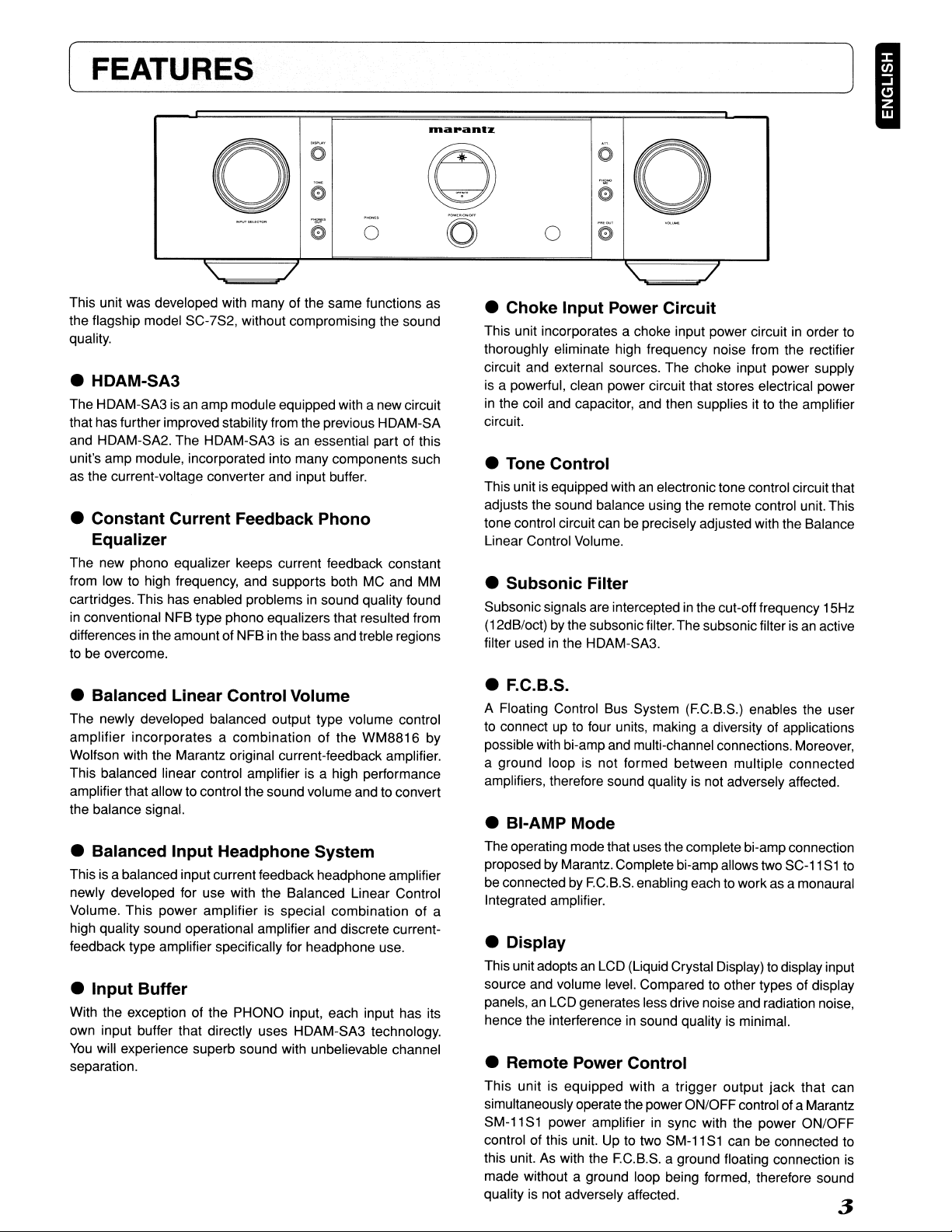
This unit was developed with many of the same functions as
the flagship model SC-7S2, without compromising the sound
quality.
• HDAM-SA3
The HDAM-SA3isan
that has further improved stability from the previous HDAM-SA
and HDAM-SA2. The HDAM-SA3
unit's amp module, incorporated into many components such
as the current-voltage
• Constant Current Feedback Phono
Equalizer
The new phono equalizer keeps current feedback constant
from low to high frequency, and supports both MC and MM
cartridges. This has enabled problems
in
conventional NFB type phono equalizers that resulted from
in
differences
to be
overcome.
the amount of NFBinthe bass and treble regions
amp module equipped with a new circuit
converter and input buffer.
"to!'
e
-
0
/
isanessential part of this
in
sound quality found
0
rnapan'z
0)
0
..,...
e
0
"
--
/
is
an active
0
• Choke Input Power Circuit
This unit incorporates a choke input power circuitinorder
thoroughly eliminate high frequency noise from the rectifier
circuit and external sources. The choke input power supply
is
a powerful, clean power circuit that stores electrical power
in
the coil and capacitor, and then supplies it to the amplifier
circuit.
• Tone Control
This unitisequipped withanelectronictone control circuit that
adjusts the sound balance using the remote control unit. This
tone control circuit can be precisely adjusted with the Balance
Linear Control Volume.
• Subsonic Filter
Subsonic signals are interceptedinthe cut-off frequency 15Hz
(12dB/oct) by the subsonic filter. The subsonic filter
filter usedinthe HDAM-SA3.
a
to
• Balanced Linear Control Volume
The newly developed balanced output type volume control
amplifier incorporates a combination of the WM8816 by
Wolfson with the Marantz original current-feedback amplifier.
This balanced linear control amplifier
amplifier that allow to control the sound volume and to
the balance signal.
• Balanced Input Headphone System
Thisisa balanced input current feedback headphone amplifier
newly developed for use with the Balanced Linear Control
Volume. This power amplifier is special combination of a
high quality sound operational amplifier and discrete currentfeedback type amplifier specifically for headphone use.
• Input Buffer
With the exception of the PHONO input, each input has its
own input buffer that directly uses HDAM-SA3 technology.
You
will experience superb sound with unbelievable channel
separation.
is
a high performance
convert
• F.C.B.S,
A Floating Control Bus System (EC.B.S.) enables the user
to
connectupto
possible with bi-amp and multi-channel connections.
a ground loop is not formed between multiple connected
amplifiers, therefore sound quality
• BI-AMP Mode
The operating mode that uses the complete bi-amp connection
proposed
be
connectedbyEC.B.S. enabling each to work as a monaural
Integrated amplifier.
• Display
This unit adoptsanLCD (Liquid Crystal Display)todisplay input
source and volume
panels,
an
hence the interference
• Remote Power Control
This unit is equipped with a trigger output jack that can
simultaneously operate the power ON/OFF control of a Marantz
SM-11 S1 power amplifier
control of this unit. Up to two SM-11
this unit. As with the EC.B.S. a ground floating connection is
made without a ground loop being formed, therefore sound
quality
is
four units, making a diversity of applications
Moreover,
is
not adversely affected.
by
Marantz. Complete bi-amp allows two
level. Compared to other types of display
LCD generates less drive noise and radiation noise,
in
sound qualityisminimal.
in
sync with the power ON/OFF
S1
can be connected to
not adversely affected.
SC-11S1to
3
[ EQUIPMENT MAINSWORKING
SETTING
Your
Marantz product has been prepared to comply with the
and
household power
-Power requirements (U.S.A.)AC 120V 60Hz
-Power requirements (Europe)AC 230V SO/60Hz
safety requirements that existinyour
area.
(COPYRIGHT
Recording and playback of any material may require consent.
For further information refer to the following:
-Copyright Act 1956
-Dramatic and Musical Performers Act 1958
-Performers Protection Acts 1963 and 1972
-Any subsequent statutory enactments and orders
INAPPROPRIATE PLACES FOR
INSTALLATION
To
keep your playerinperfectworking order
time, avoid installing the player
• Wherever it will be exposed to direct sunlight
• Wherever it will be close to a heater or other heat-radiating
appliance
• Wherever the humidity
• Wherever it is very dusty
• Wherever it will be subject to vibration
• On top of a rickety stand or
tilted at an angle
In
an audio rack with little space atthe top and bottom or other
•
location where the heat dissipation will be obstructed
To
ensure proper heat dissipation, install the player while
leaving clearances between the player and wall or other
components, as shown
0.2
m
or
more
0:
o 0
in
is
high or ventilation is poor
in
in
the figure below.
0
goo
for
the longest possible
the following locations.
an unstable location which is
0.2
mormore
:0
]
0.2
mormore
•
Do
not place objects on top
• Refrain from placing any objects on top of the player.
• Cautions on handling power cord
• Do not touch the power cord with wet hands.
• When disconnecting the power cord, always make sure that
you take hold of the plug. Yanking out
can damage it and/or cause electric shocks or a fire.
• Get into the habit of disconnecting the power plug before
leaving home.
or
bending the cord
4
[__B_E_F_O_R_E_U_S_IN_G
• Loading batteries• Usage of remote controller
Before using the remote controller for the first time, load the
batteries
used to verify the operations of the remote controller only.
1. Remove the battery cover.
in
the remote controller. The batteries provided are
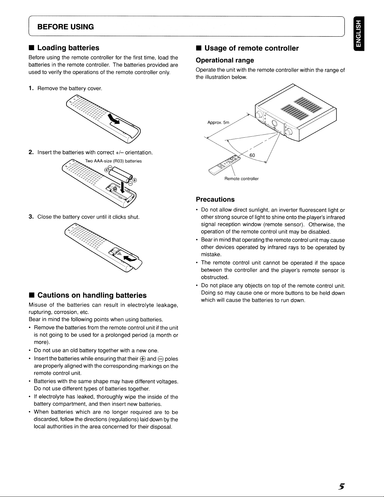
Operational range
Operate the unit with the remote controller within the range of
the illustration below.
~]
I
2. Insert the batteries with correct
3. Close the battery cover until it clicks shut.
+/-
orientation.
• Cautions on handling batteries
Misuse of the batteries can resultinelectrolyte leakage,
rupturing, corrosion, etc.
in
Bear
• Remove the batteries from the remote control unit
•
• Insert the batteries while ensuring that their
• Batteries with the same shape may have different voltages.
•
• When batteries which are
mind the following points when using batteries.
if
the unit
is
not going to be used for a prolonged period (a month or
more).
Do
not use an old battery together with a new one.
EEl
and 8 poles
are properly aligned with the corresponding markings
remote control unit.
Do
not use different types of batteries together.
If
electrolyte has leaked, thoroughly wipe the inside of the
battery compartment, and then insert new batteries.
no
longer required are to be
discarded, follow the directions (regulations) laid down
in
local authorities
the area concerned for their disposal.
on
by
the
the
Remote controller
Precautions
•Donot allow direct sunlight,aninverter fluorescent light or
to
other strong source of light
signal reception window (remote sensor). Otherwise, the
operation of the remote control unit may be disabled.
in
• Bear
• The remote control unit cannot be operated if the space
•
mind that operating the remote control unit may cause
other devices operated
mistake.
between the controller and the player's remote sensor
obstructed.
Do
not place any objectsontop of the remote control unit.
Doing so may cause one or more buttons
which will cause the batteries
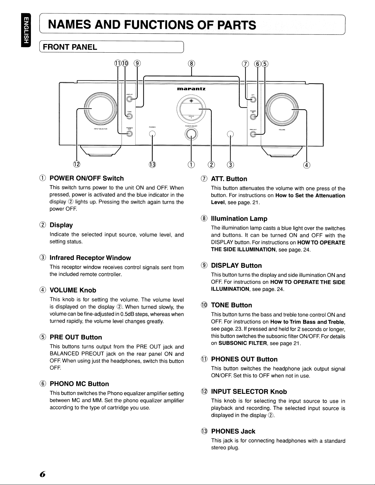
This switch turns power to the unit ON and
pressed, power is activated and the blue indicatorinthe
display
@ lights up. Pressing the switch again turns the
power
OFF.
en
Display
Indicate the selected input source, volume level, and
setting status.
® Infrared Receptor Window
This receptor window receives control signals sent from
the included remote controller.
® VOLUME Knob
This knob is for setting the volume. The volume level
is
displayed on the display @. When turned slowly, the
volume can be fine-adjustedinO.5dB
turned rapidly, the volume level changes greatly.
® PRE OUT Button
This buttons turns output from the PRE OUT jack and
BALANCED PREOUT jack on the rear panel ON and
OFF.
When using just the headphones, switch this button
OFF.
® PHONO MC Button
This button switches the Phono equalizer amplifier setting
between MC and MM. Set the phono equalizer amplifier
according to the type of cartridge you use.
=!="=!
steps, whereas when
OFF.
(0
When
-I:;::I===J......""......."
=::-0
2
I=-===I-e""""\==~r41---J
(J)
ATT.
Button
This button attenuates the volume with one press of the
button. For instructions on
see page. 21.
Level,
® Illumination Lamp
The illumination lamp casts a blue light over the switches
and buttons. It can be turned ON and
DISPLAY button. For instructions on
THE
SIDE ILLUMINATION, see page. 24.
® DISPLAY Button
This button turns the display and side illumination ON and
OFF.
For instructions on HOWTO OPERATE
ILLUMINATION,
@ TONE Button
This button turns the bass and treble tone control ON and
OFF.
For instructions on
see page. 23. If pressed and held for 2 seconds or longer,
this button switches the subsonic filter ON/OFF. For details
on
SUBSONIC FILTER, see page 21.
@ PHONES OUT Button
This button switches the headphone jack output signal
ON/OFF. Set this to OFF when not
@ INPUT SELECTOR Knob
This knob is for selecting the input source to use in
playback and recording. The selected input source is
displayed in the display
see page. 24.
How
to Set the Attenuation
OFF
HOWTO
HowtoTrim Bass and Treble,
in
use.
@.
with the
OPERATE
THE
SIDE
@ PHONES Jack
This jack is for connecting headphones with a standard
stereo plug.
6
[~_N_A_M_E_S_A_N_D_F_U_N_C_T_IO_N_S_O_F_P_'A_R_TS
J I
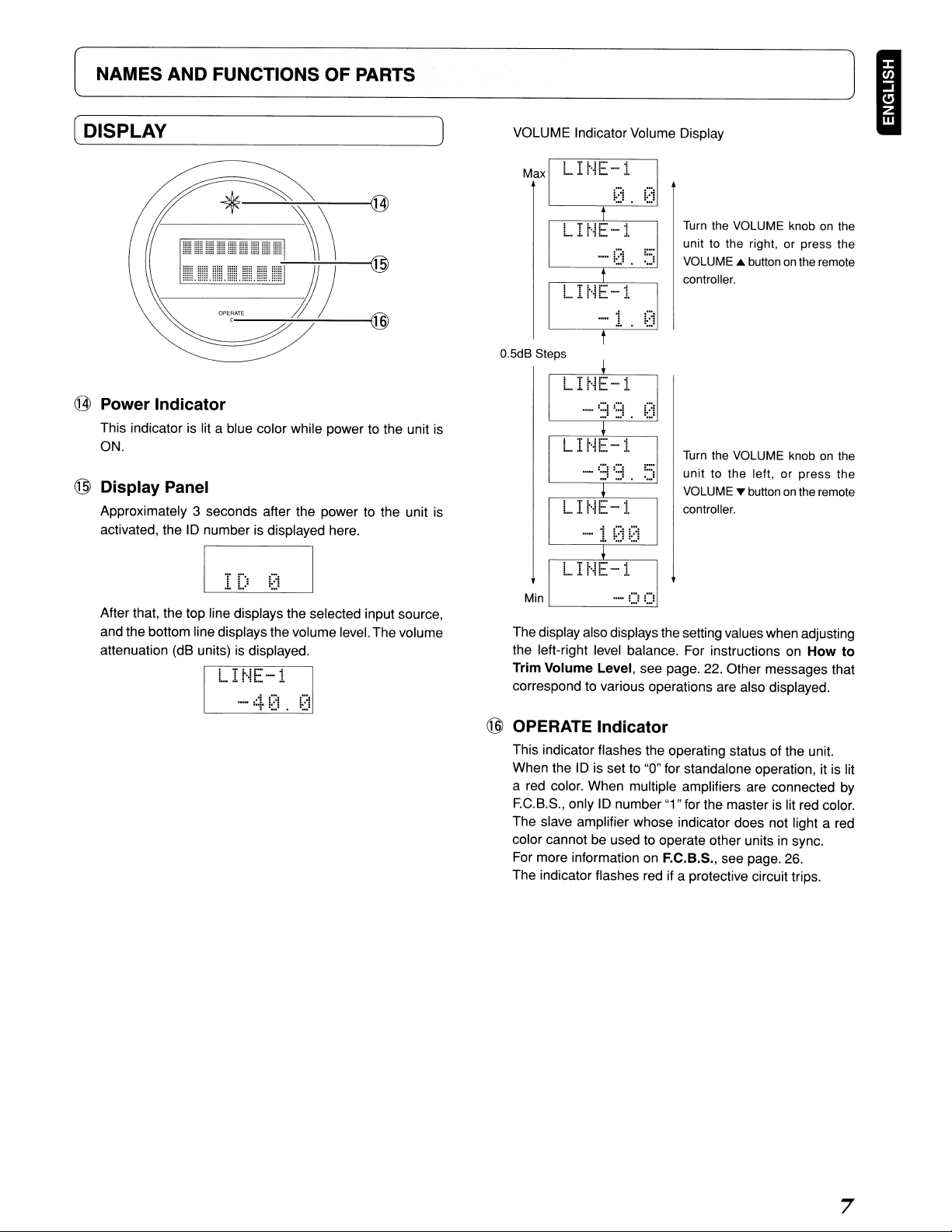
( DISPLAYVOLUME Indicator Volume Display
Max
@ Power Indicator
This indicator is lit a blue color while power to the unit
ON.
@ Display Panel
Approximately 3 seconds after the power to the unit is
ID
activated, the
After that, the top line displays the selected input source,
and the bottom line displays the volume level.The volume
attenuation (dB units) is displayed.
number is displayed here.
L
H~E-i
t
.....
i2~.
t
Turn
the VOLUME knobonthe
unit to the right, or press the
::;
VOLUME
controller.
A button
on
the remote
LHH:.-1
.....
_.
1.
i.
...
!
'_0'
O.5dB Steps
LH~E-1
is
Turn
the VOLUME knobonthe
LI r'iE-1
_.
1
~::~
unit to the left,
VOLUME ... button
controller.
!::)
or
press
on
the remote
the
LIr··IE-··l
Min
The display also displays the setting values when adjusting
the left-right level balance. For instructions
Trim Volume Level, see page. 22. Other messages that
correspond to various operations are also displayed.
..
- U
!,..!
on
How to
@ OPERATE Indicator
This indicator flashes the operating status of the unit.
ID
When the
a red color. When multiple amplifiers are connected
F.G.B.S., onlyIDnumber "1" for the master is lit red color.
The slave amplifier whose indicator does not light a red
color cannot
For more information on F.e.B.S., see page. 26.
The indicator flashes red if a protective circuit trips.
is set to "0" for standalone operation,itis lit
be
used to operate other units in sync.
by
7
[NAMES
AND
FUNCTIONS OF PARTS
]
I
(REAR PANEL
@ PHONO GND Terminal
Connect the grounding wire fromananalog record player
here.
@ PHONO
These jacks are for connecting to an analog record player.
Both MC and
the PHONO
the type of cartridge
These jacks are for connecting to the output jacks of a
tuner,
Input
DVD
Input
Jacks
MM
cartridges can be used, therefore set
MC
button ®onthe front panel according to
you
are using.
Jacks
Input
Jacks
player, etc.
H
@
lDaranlZ
MODEL NO. SC·11S1
C8>
ACINPower Cable Connection Socket
Connect this socket to the power outlet using the included
power cable.
CD
REMOTE POWER CONTROL
(TRIGGER OUT)
This jack is for connecting to the TRIGGERINjack of a
Marantz SM-11 S1 stereo powered amplifier used when
simultaneously switching the power of both devices
ON/OFF. For more information
CONTROL, see page. 25.
Q)
AMP MODE Switch
STEREO: Set to use this unit asanordinary stereo control
amplifier.
Set
BI-AMP:
For more information
to use
connection.
@
this
on
BI-AMP MODE, see page. 24.
ACIN
Jack
on
REMOTE POWER
unitincomplete
bi-amp
CE)
RECORDER 1/2
These jacks are for connecting to the output jacks of a
tape deck or other type of recording device.
® RECORDER 1/2
These jacks are for connecting to the recording input jacks
of a tape deck etc.
.ese uttons are or se ectmg t e mput source to use
This remote controller canbeused to control the
Marantz Super Audio CD players or
remote control receptor. The operations possible
control may differ with each component, therefore see the
instruction manual that came with the component.
This button starts the various trim adjustments. (Page.
22)
When multiple units are connectedbyF.C.B.S., this button
selects the unit with which to perform trimming.
[l]
EXIT
This button ends the trimming mode when trimming is
finished.
@]
TONE
This button turns tone (bass Itreble) control ON and
OFF.
W ATT
This button attenuates volume level with one press. (page.
21)
[§]
Volume
AThis button increases the volume level.
T : This button decreases the volume level.
Button
Button
Button
Button
Buttons
h'
m
<1<1
c::::::::::J
.....,..
TOP
MENU
Dlapantz
C>
00
0
"""
"""~
"""
<11>
[I] DISPLAY
This button turns the display ON and
lID
9
Cursor
In
the
These buttons are for selecting the channel to trim and
the trimming level.
ENTER:
~/R
<OlIn
AI
+
T/-
Button
OFF.
Buttons
Trimming
Mode
This button selects the trim mode
(LEVEUBASSITREBLE).
This
button
trimming.
This button selects the L channel for trimming.
This button increases the trimming level.
This button decreases the trimming level.
selects
theRchannel
for
Other
than
the
Trimming
~,
<OIl,
A,
T and ENTER: These buttons are for selecting
settings items on menu displays of Marantz
etc. For operations of supported Marantz products, see the
tables
on
the following page and the instruction manual of
the Marantz component.
[ID
Component
These buttons are for operating Marantz Super Audio CD
players,
Marantz products, see the tables
the instruction manual of the Marantz component.
Operating
DVD
players, etc. For operations of supported
Mode
Buttons
DVD
on
the following page and
players,
9
NAMES
[
AND
FUNCTIONS
OF
PARTS
]
I
The buttonsingroups
DVD
players.
The function of each button changes to match the component selected as the input source from the INPUT SELECT buttons
• Remote Controller Operation for Marantz
Super Audio CD Players
When the CD button is pressed, the buttonsingroups
lID
function as indicated in the table below. These buttons
can be used only when a Marantz Super Audio CD player is
connected to the CD input jacks.
Button
OPEN/CLOSEOpen/Closes disc
SOUND MODE
~
~
~
....
~
II
•
RANDAMRandom play
SCANAMS (Automatic Music Scan) play
REPEATRepeat play
TOP MENU/AM/A Not available for use
RETURN/FM/B
<II~
MENU
ENTERStarts quick replay.
&/+
~
/-
<II/L
~/R
[[]
and
lID
are for operating Marantz products other than the SC-11S1, such as Super Audio CD players or
[[]
Function
tray.
CD
Selects Super Audio
Selects Super Audio CD/CD.
Play
Track skip
(Returns to track beginning/previous track.)
Track skip (Advances to next track.)
Rewind search
Forward search
Pause
Stop
Not available for use
Sets quick replay.
Not available for use
Not available for use
Not available for use
Not available for use
sound mode.
and
• Remote Controller Operation for Marantz DVD
Players
When the LINE 2 button is pressed, the buttonsingroups
andrnfunction as indicatedinthe below table. These buttons
can be used only when a Marantz
the LINE 2 input jacks.
ButtonFunction
OPEN/CLOSE
SOUND MODEChanges sound mode.
~
~
~
....
~
II
•
RANDAMRandom play
SCANSelects search mode.
REPEATRepeat play
TOP MENU/AM/A Displays top menu.
RETURN/FM/BReturns to previous menu
MENU
<II~
ENTERSets selected item.
&/+
~
/-
<II/L
~/R
Open/Closes disc
Play
Track skip
(Returns to track beginning/previous track.)
Track skip (Advances to next track.)
Rewind search
Forward search
Pause
Stop
Displays menu screen.
Moves cursor upward.
Moves cursor downward.
Moves cursor to left.
Moves cursor to right.
Marantz
Refer to these connection examples when connecting to
different amplifiers.
Notes:
SM-11S1stereo power amplifier.
Do
not connect the power cord of this unit or any of the
•
other components to the power supply until all of the
connections are completed.
• Insert the plugs of the connections cords firmly into the
connecting jacks. Incorrect insertion may cause noise.
• Connect the wires correctly to the L (left) and R (right)
channels. The red jack is the R (right) channel, and the
is
white jack
• Make sure that input and output are connected correctly.
• Refer also to the instruction manuals of components
connect equipment correctly.
the L (left) channel.
(~B_A_L_A_N_C_E_D_J_A_C_=____K___.:S=____
CD
The BALANCED jacksonthis unit are equipped with XLR
connectors that are widely used
Their features are listed below.
• The 3 pin construction enables the musical signal to be
transmitted as a balanced signal, with little effect from
external noise
• The detachable locking mechanism minimizes connector
play and enhances connection reliability.
@ The XLR connector for professional use
in
either of the following two systems.
1.
USA system (Pin @ =COLD, Pin ® =HOT)
to
colW
2.
European system (Pin @ =
on
professional equipment.
is
internally wired
l
HOT,
Pin ® =COLD)
P
~)
® This unit uses the
When a preamp or main amplifier adopting the European
system is connected using a cable with XLR balanced
connectors, the reproduced signal may be inverted of
phase.
In
this case, referto"ANALOG OUTPUT CONNECTOR
PHASE SWITCHING", and set so that the correct phase
is
used.
1.
USA system.
[
CONNECTIONS
]
I
• Connection Example1: Basic Connection for Normal Stereo Playback
The two amplifiers are connected by EG.B.S. for synchronized use. For EG.B.S. connection, connect with commercially available
monaural
CIl
Set the10numbers as explainedinHOW TO SET10NUMBERS (page. 27). When the
amplifier will operate
® Connect the analog output of the
As
• About Complete Bi-Amp
Proposed by Marantz, the complete bi-amp connection is an advanced technique that enhances sound quality. The low and mid/high
amplifiers are separated and independent of the preamplifier, therefore interference between low and mid/high sounds is reduced
to a minimum. As a result, a wide sound environment can be reproduced.
Note:
Speaker systems connected using complete bi-amp connections must support bi-amp connections. Before connecting your
speakers, check
support bi-amp connection.
5C-1151 for L ch
• Set to
Q monaural miniplugs or stereo Q stereo miniplugs as described
in
sync.
GO
player etc. to the Lchinput jacks of both pre-amps.
both pre-amps operate as monaural pre-ampsinBI-AMP mode, do not use the R channel of the input jacksonthese units.
in
the instruction manual that came with the speakers or contact the manufacturer to confirm whether they
10
1
in
F.C.B.S. (page. 26).
101
amplifier is operated, the102
To
power outlet
@
L ch for 5M-11 51
@
~..:..----~-
@
@
@
SettoBI-AMP
F.C.B.S.-
F.C.B.S.
+-
@
@
14
Remove
shorting bar
Speaker
L ch
Remove
shorting bar
[~_C_O_N_N_E_C_TI_O_N_S
CD
Player
~]
I
""
~
_
""-1-npn·"I&
~
_MOOt;'...,
(;]~
"
R
....
"a.
..
f
ISC-11S1 for R ch I
• Setto102
----+
+--
F.G.B.S.
F.G.B.S.
I R
ch
for SM-11S1
AC
IN
To
power outlet
~
@
Set
to
BI-AMP
@
7
-~-To
@
o
@
@
@
@
@
o
@
@
power outlet
RemoveSpeaker
shorting barR
ch
CONNECTIONS]
(
I
• Connection Example3:Basic Connection for
CD
The three units are connected using
on
F.e.B.S.
@ Set the
When the
G)
Connect the outputs of players that have
@
If
usinganactive subwoofer, see the instruction manual that came with the subwoofer for further instructions.
For front
• SettoID
page 26.
10
numbers for the three amplifiers as explained
10
1 pre-amp
UR
1
@
is
operated,
F.C.B.S.
102
For the F.C.B.S connection, prepare 3 audio connection cables, and refer to
in
and
103
pre-amps will operateinsync.
5.1
channel analog outputs to each of the three pre-amps.
5.1
Multi-Channel Playback
HOWTO SET10NUMBERS (page. 27).
~~---~-:-Set
Miniplug connecting cord x 3
(commercially available)
To
power outlet
to
STEREO
F.G.B.S.
-----+
For front
SM-11S1
UR
@
Front R ch
Speaker
•
F.G.B.S.
----Set
@
to STEREO
----To
@
@
@
@
@
@
Front L ch
Speaker
power outlet
+--
[~_C_O_N_N_E_C_T_IO_N_S
Su
er AudioCDMulti-channel Pia er
Mum
@
@
CHANNEL AUDIO OUT
AC
IN
To
power outlet
0
>
For centerl
subwoofer
• Set to102
s
@@I
I
R
101
A
0
00
@)@)@)@)
@
;
I
)
~]
I
For center
SM-11S1
@
~
@
@
@
r;=:=:>\
~
~.II~,
~ ~
~
ti.
L-.-----"""'----------'
'""':-:----~~
Set to STEREO
to page. 18
------.
----
@
0
""-"""
__
II"
SYSTEM 1
SYSnMI
ANO
I
~_®»J:.
~
~
@
Oil
SY$TEN2:
SYSTEM2:.16
t e
Set to STEREO
._.
OHMS
BTL;•O+1M$
OHMS
BTL:16QHMS
~_@_LCH~
~
~
~
@
@
@
@
~~To
@
~
@
@
power outlet
•
•
To
line input
jack
Center speakerAmplifier built-in
subwoofer
17
I[
CONNECTIONS
From page. 17
-+
]
IFor surround
• Set to103
__Fr..
_
UR
I
&L.;p~IG~rn~~~~~~I-']
®
om......
pa_g_e~_1_7
EC.B.S.-+
EC.B.S.
+--
For surround
SM·11S1
UR
o
®
®®
I
_---Set
""':"f'~~,"".
'-
~
~ ~
~
.-
Ctl
~
.=1
==
r:STEREO
BTl
Ir
®
SYSTEM 1 OR SYSTEM 2 ,
SYSTEM 1
.HO
SYSTEM2 : 8-16
@:::StA
it:t!
to STEREO
.m:,:."il8.
4·
a OHMS
BTL:
OHMS
BTL:16OHMS
®
@ACIN
r€[~J£e
:~15~-~II
I--!I
..
~~A
\
.....
~~.,..7
®
JI
J
• OHMS
®
®
®
®
-~-To
®
®
To
power outlet
Set to STEREO
power outlet
18
Surround R
Speaker
..
ch
Surround L ch
Speaker
['--_C_O_N_N_E_C_T_IO_N_S
~]
I
SPEAKER
AUDIO
In
ordertoenjoy Super Audio CD multi-channel sound with
the best possible acoustics, it is recommended to position
speakers as specified
Telecommunication Union (ITU). Super AudioCDmulti-channel
discs are recorded and mixed so as to achieve the optimum
effect with a speaker system laid out as specified
BS.775-1.
• With Super Audio CD multi-channel discs, the music signals
are basically recorded using 5 channels
sometimes), but
recorded as a sixth channel. Each disc indicates how many
channels have been recorded on
• The basic layoutis3 speakersinthe front and 2inthe back
since multi-channel discs usually have 5 channels. The 2
front, 1center and 2 surround (rear) speakers should be set
in
acircle around the listening point as shown below.Ifusing
speakers of differing sizes, adjust volume balance from the
amplifier.
• The location of the subwoofer
explanatory purposes. It can be located anywhere
room. For connection and positioning instructions, see the
instruction manual that came with the subwoofer.
POSITIONING
MULTI-CHANNEL
in
ITU-R BS.775-1 of the International
in
some cases, LFE (for subwoofer)
FOR
SUPER
SOUND
(3
- 6 channels
it.
in
the figure is just for
in
ITU-R
in
the
(CONNECTINGTHE POWER
1. Plug the power cable into
is
2.
Turn on the power switch of the audio unit (amplifier, etc.)
that is connected with this unit. Set the selector on the
to
connected unit
3. Plug the power cable into
this unit.
ACINjack on the back panel.
anACoutlet.
SUPPLY)
• ITU (International Telecommunication Union)
The ITUisa special organization of the United Nations.
consists of a number of organs, one of which is the Radio
Broadcasting Section.
BSinthe recommendation which consists of standards
ITU-R
to
relating
ITU-R BS.775-1 which governs "multi-channel stereo sound
systems."
broadcasting (audio) operations, one of which is the
Sub·woofer
Front speaker
(left)
II
Center
~
speaker
It
19
BASIC OPERATION
(
]
I
( PLAYBACK
To
explain how to play back input sources, typical examples
are given with disc playback from a Super Audio CD player
and record playback from
Refer to the connection procedures and check that each
component
is
correctly connected to the amplifier.
an
analog record player.
• Disc Playback on a Super Audio CD
Player
1.
Press the power ON/OFF switch of the Super Audio CD
player to activate power to
2.
Press the power ON/OFF switchCDon the unit to activate
power to
F.C.B.S., turn the power ON
ID
3.
Select the input source from the INPUT SELECTOR knob
@
remote controller.
4.
Press the PRE OUT ® button to switch output from the
unit ON.
5.
Turn on the power to the connected power amp.
6.
Load a disc into the Super Audio CD player and press the
PLAY button to start playback.
7.
Adjust the volume level using the VOLUME knob ® on
the unit or the VOLUME
controller.
8.
You
suited for the room environment. Press the DISPLAY button
it.
When using multiple amplifiers connected by
number.
on
the unit, or the INPUT SELECT buttonsOJof the
can turn the display and side illumination ON/OFF as
Press the power ON/OFFCDswitch of the unit to activate
power to
F.C.B.S., turn the power ONinthe orderof lowest to highest
ID
2. Select the PHONO using the INPUT SELECTOR knob
® on the unit, or the INPUT SELECT buttons
remote controller.
recommended to set the volume level to
turning the VOLUME knob
3.
Set the PHONO MC button ® to MM or MC according to
the cartridge you are using.
4.
Press the PRE OUT ® button to switch output from the
unit ON.
5.
Turn on the power to the connected power amp.
6. Set a record on the analog record player and play
7.
Adjust the volume level using the VOLUME knob ® on
the unit or the VOLUME
controller.
8.
You
suited for the room environment. Press the DISPLAY button
® on the unit or the DISPLAY button
controller.
it.
When using multiple amplifiers connected
number.
OJ
of the
To
prevent unexpected accidents, it is
-00
(mute) by
®.
it.
A/T
buttons
can turn the display and side illumination ON/OFF as
[§]
on the remote
[I]
on the remote
by
Rlapanlz
20
[~H_O_W_TO_U_S_E
_A_N_D_S_ET_FE_A_T_U_R_E_S
J I
(ATT. (ATTENUATION)
ATT.
button
0
0
e
e
An
is a one-touch feature for reducing the volume level. When
the
An
buttononeitherthe unit or remote controller is pressed,
the volume level is attenuated.
1. When the
controller is pressed, "ATT" flashes
volume level is reduced.
When the
is increased/decreased using the controls, the mode is
canceled and the original volume level is restored.
2. When the
-oo(muted), the display will change as
appears for
applied.
ATT
ATT
An
about
0
0
button on either the unit or the remote
button is pressed again or the volume
button is pressed with the volume level at
0)0
LI
f··H::.-1
3 seconds, and attenuation is not
LH~E-
:••: '1' : :
i:i
J.
J.
r"~
t;
e
G
on
the display and the
it
is shown below
• How to Set Attenuation Level
Attenuation level can only be set using the
unit. The attenuation level can be set at
The factory default setting is -20dB.
1. Press and hold the
longer. The attenuation level will appear on the display.
ATT
button on the unit for 2 seconds or
L
H~E-1
An
-20dB,
button on the
-40dB, or
-00.
(~S_U_B_SO_N_I_C_F_IL_T_ER
TONE button
~
~
e0
If
a warped analog record ordisc recorded with super-low bass
is played, the speaker diaphragm may vibrate unusually and
the disc may not be played correctly.
In
such cases, the subsonic filter can be set to block the
super-low bass output component. Press the TONE button for
2 seconds or more to set the subsonic filter ON/OFF.
When the subsonic filter is switched from ON to
OFF condition of the subsonic filter is displayed for 3 seconds,
as shown below.
After displaying the ON/OFF condition, the display returns to
the volume display.
Display before
pressing the
TONE button
Press the TONE
button for 2
seconds or longer
Display after
seconds have
passed
3
T
r·~1::.
-
L
::;1
...iE;::::;C)I··~
L
:~:;
Set to
i
1
.....
.....
:0':
::':.
,
::..:
+
_.
T
I
J•
...
i
...
L
T
1
"iL.
...
...
!-o!
i
i
-:
++
ir-
-
1
:
i..:
:-i'
.....
ON
o
~:J
...
.:
~:,!
60
o
1
I
L
.'.
::::
::;
jJ
E:
I
L
Set to OFF
OFF,
ft.
r'i
!:.
.
....
:::1·
•
::;()'-'1
...
I
i::'
i
i
..
: i
'
..
r'i
t:.
_
..
:::i·
~)
the ON/
-
i
C:,
.....
I C
i
...
-
i
~~i
!:~i
.
....
:..:
::..=
2. The attenuation level setting value changes with each press
of the
An
buttononthe unit.
3. When the desired attenuation level setting appears on the
display, leave it unchanged for 2 seconds or longer to enter
the setting. Once entered, the display returns to the volume
level indication.
LIr··iE-·J.
H~E
L
--1
21
I
[~_H_O_W_T_O_U_S_E_A_N_D_S_E_T_FE_A_:r_U_R_E_S
II
(TRIMMING• How
There are three trimming modes.
on
• LEVEL trimming that adjusts the volume level
right channels
• BASS trimming that adjusts the bass on left and right
channels
• TREBLE trimming that adjusts the treble
channels
on
left and
left and right
The volume level of the left and right channels can be trimmed
in
0.5dB steps across a 0.0 is shipped from the factory, the volume level is set to
(maximum).
1.
to
Trim Volume Level
9.OdB
range. When the unit
Press the TRIM button once to access the LEVEL trimming
mode.
~]
O.OdB
Note:
Trimming is performed from the remote controller.
2. The flashing "0.0" on the left indicates that trimming is
TRIM
EXIT
•
T
ENTER
:Thisbutton starts trimming. When multiple
are connected, this button selects the amplifier with
In
which to perform trimming.
is performed
number.
This button ends trimming.
This button increases the trimming level.
This button decreases the trimming level.
This button selects the R channel for trimming.
~
This button selects the L channel for trimming.
~
This button selects the trim mode (LEVEL, BASS
orTREBLE).
in
the order of the lowest to highest
such case, trimming
SC-11
S1s
10
activated for the left channel volume level. Press
T buttons to set the volume level of the left channel.
L LEi,}EL
3. Press the~button to set the right channel volume level.
When the right side "0.0" starts flashing, trimming is
activated for the right channel volume level. Press
T buttons to set the volume level of the right channel.
4.Totrim the volume level of the
TRIM button again and set the volume level as in steps
1-3.
After that, pressing the TRIM button again allows you
to trim the volume level for the
5. When finished with volume level trimming, press the EXIT
button.
102
(slave) unit, press the
"10
3" unit and so forth.
22
[
H_O_W_T_O_U_S_E_A_N_D_S_E_T_F_E_A_:T_U_R_E_S
------------]
• How toTrim Bass• How toTrim Treble
The bass level of the left and right channels can be trimmed
in
2dB steps across a
shipped from the factory, the bass levelisset to 0 dB.Totrim
the bass level, active tone control
on
either the unit or the remote controller.
1.
Press theTRIM button once to access the LEVEL trimming
mode.
-8.0
- +8.0dB range. When this unit
by
pressing the TONE button
is
The treble level of the left and right channels can be trimmed
in
2dB steps across a
shipped from the factory, the bass levelisset to 0 dB.Totrim
the treble level, active tone control
on either the unit or the remote controller.
1.
Press the TRIM button oncetoaccess the LEVEL trimming
mode.
-8.0
L LE')EL P
.-
.
t:i.!:::i
2.
Press the ENTER button once to access the BASS trimming
mode.
3.
The flashing "0" on the left indicates that trimming
activated for the left channel bass level. Press the
...
buttons to set the bass level of the left channel.
, ,
1'
.
..j••
~::
•
.
.....
is
...
and
2.
Press the ENTER button twice to access the TREBLE
trimming mode.
3.
The flashing "0" on the left indicates that trimming is
activated for the left channel treble level. Press the
...
buttons to set the treble level of the left channel.
- +8.0dB range. When this unit
by
pressing the TONE button
...
I
is
and
4.
Press the~buttontostartthe "0" on the right side flashing.
is
...
and'"
in
activated
buttons
steps 2-4.
When the right side "0" starts flashing, trimming
for the right channel bass level. Press the
to set the bass level of the right channel.
5.Totrim the bass level of the102 (slave) unit, press the
TRIM button again and set the bass level as
After that, pressing the TRIM button again allows you
trim the bass level for the
6.
When finished with bass level trimming, press the EXIT
button.
"10
3" unit and so forth.
4.
Press the~button to start the "0"onthe right side flashing.
is
and'"
in
activated
buttons
steps 2-4.
When the right side "0"starts flashing, trimming
for the right channel treble level. Press the ...
to set the treble level of the right channel.
To
trim the treble level of the102 (slave) unit, press the
5.
TRIM button again and set the treble level as
to
After that, pressing the TRIM button again allows you to
"10
trim the treble level for the
6.
When finished with treble level trimming, press the EXIT
button.
3" unit and so forth.
23
[HOWTO USE
AND
SET
FEATURES
]
I
HOWTO OPERATETHE SIDE
ILLUMINATION
DISPLAY
bUJ"
o:~
--
e
~
The illumination lamp hasanalways-ON mode (factory setting)
an
always-OFF mode.
and
In
the always-ON mode, the illumination lamp turns ON/OFF
in
sync with the display.
1.
With the illumination lamp lit, press and hold the DISPLAY
button for 3 seconds or longer. The illumination lamp goes
out, and the always-OFF mode
2.Tocancel the always-OFF mode and turn the illumination
lamp ON, press and hold the DISPLAY button for 3 seconds
or longer.
Illumination
lnapanlZ
CO
-
00
0)
Lamp
I
°:0
is
engaged.
--
e
~
('-B_I-_AM_P_M_O_DE
This unit
bi-amp connection using two SC-11 S1
amp connection is a high-end technique for enhancing sound
quality, proposed
supporting speaker system
that separately drive the low and high speakers. (For more
information, see
The bi-amp modeisengaged by setting the operating mode
switch on the rear panel to "BI-AMP".ln the bi-amp mode, the
signals input to the L channel are split
sent to the left and right volume amplifiers, and are then output
to the PRE OUT terminals. The figures below show example
displays
Notes:
is
equipped with a bi-amp mode to enable a complete
s.
This complete bi-
by
Marantz. Using this system, the bi-amp
is
separated from the preamplifiers
Connection
in
the stereo and bi-amp modes.
Stereo mode
L
H~E-1
--4[1.0
o When
o When
o Always turn the power to the unit OFF before changing
in
bi-amp mode, the R channel input jacks cannot
be used.
in
bi-amp mode, the signals input into the L channel
are output from both channels. Therefore, the same
signals are output from the L channel and R channel
RECORDER OUT, PRE OUT, PHONES
the operating mode switch setting. Turning the power ON
again activates the new setting.
Example
C@]
~I-AMP
STEREO
I
by
Bi-amp mode
L
:+:
2 (page.14).)
the input selector and
H~E-l
,-,,40.0
OUT
J
in
24
[HOWTO USE AND SET FEATURES
[ REMOTE POWER CONTROL
By connecting this unit to a Marantz 8M-1181stereo power
by
amplifier
8M-1181 can be automatically switched ON/OFF
this unit's power ON/OFF control. There are 2 trigger output
terminals
controlledinsync with this unit's power ON/OFF control.
remote power control, the power supply of the
in
sync with
on
this unit, and a maximum of 2 8M-11
81s
can
be
2.
Afta<
completi"g the
remote power control ON/OFF switchonthe rear panel of
the 8M-1181 to ON.
3. Press the 8M-11
standby mode.
4.Inthis condition, press the POWER ON/OFF switch on
this unit, and the power of the 8M-11
sync.
"""ectio"s
81
POWER ON/OFF switch to switch to
show"
81
below,
switch
will switch ON in
th]
I
1.
Prepare the correct number of double-ended mini plug
audio connection cables for the number of 8M-11
be connected. Either of the following types of connection
cables are adequate.
not use connecting cables that contain resistance.
i====~\\\====[[i
SC-11
S1s over a dedicated
be
connected. Either of the
monaural miniplug connecting
1i1IIl1i1i1III[!!!I~
1 and controls the three slave units with102-4.
master unit is operated, the input source, volume level,
feature, display and tone control ON/OFF feature of the slave
units are operated
This function can be applied to various usages such as
complete bi-amp with 2
channel with 3
Note:
The
same SC-11
correctly
are connected.
EC.B.S. The top unit is the master unit with
in
sync with the master unit.
SC-11S1s (page. 14), and 5.1ch multi-
SC-11S1s (page. 16).
SC-11S1EC.B.S. function is only valid between the
S1
models. This function may not operate
if
other Marantz models (PM-11 S1, PM-15S1 etc)
When the
10
An
To
turn the powerofmUltiple F.C.B.S.-connected
number, and switch the power OFF in orderofhighesttolowest10number.
SC·llSl
•
101 Master
SC·11S1
•
units
ON/OFF, switch the powerONin
•
102
Slave
SC-llSl
•••
103
Slave
SC-llSl
••
104
Slave
orderoflowesttohighest
~
@@
~
10
t
26
[~_H_O_W_T_O_U_S_E_A_N_D_S_E_T_F_E_A_:r_U_R_E_S
---------~]
I
(HOW TO SET10NUMBERSDISPLAY button
If
using this unit by itself as a stereo amplifier, set the10number
to "0" (Default setting is "0").
Note:
If
the10number is set to a number other than "0", this unit
cannot be used for standalone operation.
,....-..l==;=c]===~===;;;:;r=6=;=====---,
eQ0
L..-+'r"===J_e...l..-_o
__
?
0---l._(:)~==T----J
10
The
them.
number of the unit appears on the display for about 3
seconds after the power is activated.
Lo:
I
[)
::..:
When multiple SC-11S1s are connected, a unique10number
must be set of each one in order to distinguish between
The unit that centrally controls the other units takes
The unit with
synchronize with the master are called "slaves" and take IDs
"2"
"'-
"4".
101
is called the "Master". The other units that
10
INPUT SELECTOR
Knob
Set10numbers as follows.
1. While pressing and holding the DISPLAY button, press the
POWER ON/OFF switch.
1.
2. Turn
After finishing setting the10number, turn power to the unit
OFF.
The setting is storedinmemory and becomes active the next
time power to the unit is switched ON.
the
number.
INPUT
POWER ON/OFF Switch
:.':
I
[::
::..=
SELECTOR
T
f"-:
l.
;....
knobtothe
oj
.I.
desired
10
27
]
I
~
y~:~o~
checks before thinking the worst. Improper operation can
cause the SC-11S1 to behaveina way that makes you think
something is wrong with the equipment when actually not.
the trouble cannot be fixed after making the below checks,
contact the place of purchase, your nearest Marantz dealer,
our customer service center or our repair service center.
~"~e~~~~,~~~~~
below
If
• Protective Circuits
The unit is equipped with protective circuits to protect the
amplifier circuits and
protective circuit trips, the sound is instantly muted.
case, "PROTECT" flashes on the display and the OPERATE
indicatoralso flashes.
the power
switching the power back ON again.
• Power does not turn ON
Is
the power cable securely plugged into a power outlet?
• Nothing is heard from the headphones or
speakers
1.Isthe PRE OUT button on the front panel OFF?
2.Isthe PHONES OUT button on the front panel OFF?
3.Isthe
4.Isthe input source selected with the INPUT SELECTOR
5.
6.
7.
8.Ifan
ATT
(attenuation) feature active?
on the front panel correct?
Are you using the player (replaying device) correctly?
Are connection cables and
connected?
Volume may have been muted by a protective circuit that
tripped.
as indicated
Try
adjusted the volume again.
error messageisdisplayed, correctly set theIDnumber
in
the reference table.
speaker
cables securely
• Volume differs between left and right
Are the volume (LEVEL TRIM), bass, or treble levels trimmed
differently for the right and left sides?
again.
If
required, try trimming
• Sound is not stereo
The MODE switch on the rear panel may be set to "BI-AMP".
If
the unit isinbi-amp mode, shut the power
MODE switch to "STEREO" and then reactivate the power.
Power mustbeactivated after the MODE switchisset for the
setting to be active.
OFF,
set the
• At Power ON
For about 8 seconds after the power is switched ON, a
protective circuit trips and mutes the sound to give amplifier
circuits time to stabilize. Once the amplifier circuits stabilize,
the protective circuit releases and audio is enabled.
• If Strong Bass Signals Are Input
A protective circuit trips if bass signals of an excessive level
are detected. A protective circuit also trips if an abnormality
caused
by
power supply circuit.
• Error Messages
When multiple SC-11S1s are connected by F.C.B.S., the
below error messages may appear on the display.
cases, there is a problem with theIDnumbersetting or remote
cable connection. Check the
as indicatedinthe below table. For details on how to set
numbers, see HOWTO SET
Error
message
ERROR
1
ERROR
2
ERROR
3
4
ERROR
• Record player audio is not heard or contains
a lot of noise
5
1.Isthe PHONO MC button on the front panel set to match
the type of cartridge you are using?
2.
Are the connection cables securely connected?
3.Isthe grounding wire from the record player connected to
the PHONO GND terminal?
4.Isthe cartridge properly connected to the tone arm?
ERROR
headphones
To
release the protective circuits, switch
OFF,
and wait for approximately 1 minute before
such reasons as an amplifier fault is detectedinthe
must be performedtooptimize the operation of your Marantz
equipment.
• Cleaning of equipment external surfaces
The exterior finish of your unit will last indefinitely with
proper care and cleaning, Never use scouring pads, steel
wool, scourging powders or harsh chemical agents (e.g., lye
solution), alcohol, thinner, benzine, insecticide or other volatile
substances as these will mar the finish of the equipment.
Likewise, never use cloths containing chemical substances.
If
the equipment get dirty, wipe the external surfaces with a
soft, lint-free cloth.
If
the equipment becomes heavily soiled:
o dilute some washing up liquid
detergent to six parts water.
o dip a soft, lint free
o wipe the equipment with the damp cloth.
o dry the equipment
ca'.
a,d
rna;,t.'a",.
in
water,ina ratio of one part
in
the solution and wring the itisdamp.
by
wipingitwith a dry cloth.
tasks
that
• Repairs
Only the most competent and qualified service technicians
be
should
station personnel have the knowledge and special facilities
needed for repair and calibration of this precision equipment.
After the warranty period has expired, repairs will
for a charge
operation.
In
the event of difficulty, refertoyour dealer or write directly
to
the nearest locationtoyou thatislisted on the Marantz
Authorized Service Station list.
model and serial number of the equipment together with a full
description
behaviour.
allowed to service the factory-trained warranty
if
the equipment canbereturned to normal
If
writing, please include the
of
what
you
thinkisabnormal about the equipment's
be
performed
30
www.marantz.com
You can find your nearest authorized distributor or dealer on our website.


 Loading...