

MAN D2876LUE 601, D2876LUE 602, D2876LUE 603, D2876LUE 604, D2876LUE 605 Service Manual
...Page 1

Page 2

Page 3

Preface
This Repair Manual is designed to facilitate competent repair of the engines listed here in.
The pictures and relevant descriptions show typical work that may not always be applicable to the engine in
hand, which nevertheless does not mean that they are not correct.
In such cases the repair work is to be planned and carried out in a similar way.
Please note that all jobs described in this Repair Manual were carried out on an engine which was not installed.
The expert knowledge necessary for handling Diesel engines was taken for granted when this publication
was compiled.
Any repair of components such as injection pump, alternator etc. ought to be left to our or the manufacturer’s service department.
Best regards
MAN Nutzfahrzeuge Aktiengesellschaft
Nuremberg Plant
We reserve the right to make technical modifications in the course of further development.
© 2004 MAN Nutzfahrzeuge Aktiengesellschaft
Reprinting, copying or translation, even in the form of excerpts, is forbidden without the written permission
of MAN. MAN expressly reserves all rights in accordance with the law on copyright.
MTDA Technical status: 03.2004 51.99598−8107
1
Page 4
Instructions
Important instructions which concern technical safety and protection of persons are emphasised as shown
below.
Danger:
This refers to working and operating procedures which must be complied with in order to rule out
the risk to persons.
Caution:
This refers to working and operating procedures which must be complied with in order to prevent
damage to or destruction of material.
Note:
Explanations useful for understanding the working or operating procedure to be performed.
Fitting flat seals / gaskets
Flat seals / gaskets are often inserted with sealing agents or adhesives to make fitting them easier or to
achieve better sealing. Flat seals may slip in operation due to the “sewing-machine” effect, in particular if
they are used between parts with different rates of linear expansion under heat (e.g. aluminium and cast
iron), and leaks may then occur.
Example:
The cap of the front crankshaft seal. If a sealing agent or an adhesive is used here the flat seal will move
inwards in the course of time as a result of the different expansion rates of the materials. Oil will be lost, for
which the shaft seal may be thought to be responsible.
Flat seals / gaskets can be fitted properly only if the following points are observed:
D Use only genuine MAN seals / gaskets.
D The sealing faces must be undamaged and clean.
D Do not use any sealing agent or adhesive − as an aid to fitting the seals a little grease can be used if
necessary so that the seal will stick to the part to be fitted.
D Tighten bolts evenly to the specified torque.
Fitting toric seals
D Use only genuine MAN toric seals.
D The sealing faces must be undamaged and clean.
D Always wet toric seals with engine oil before fitting them.
2
Page 5

Contents
Preface 1 . . . . . . . . . . . . . . . . . . . . . . . . . . . . . . . . . . . . . . . . . . . . . . . . . . . . . . . . . . . . . . . . . . . . . . . . . . . . . . . . .
Instructions 2 . . . . . . . . . . . . . . . . . . . . . . . . . . . . . . . . . . . . . . . . . . . . . . . . . . . . . . . . . . . . . . . . . . . . . . . . . . . . . .
Engine type classification 5 . . . . . . . . . . . . . . . . . . . . . . . . . . . . . . . . . . . . . . . . . . . . . . . . . . . . . . . . . . . . . . . . . .
Safety instructions 7 . . . . . . . . . . . . . . . . . . . . . . . . . . . . . . . . . . . . . . . . . . . . . . . . . . . . . . . . . . . . . . . . . . . . . . . .
General notes on engine overhaul 9 . . . . . . . . . . . . . . . . . . . . . . . . . . . . . . . . . . . . . . . . . . . . . . . . . . . . . . . . . .
Commissioning After Engine Overhaul 10 . . . . . . . . . . . . . . . . . . . . . . . . . . . . . . . . . . . . . . . . . . . . . . . . . . . . . .
Fault table 12 . . . . . . . . . . . . . . . . . . . . . . . . . . . . . . . . . . . . . . . . . . . . . . . . . . . . . . . . . . . . . . . . . . . . . . . . . . . . . . .
Troubleshooting chart 13 . . . . . . . . . . . . . . . . . . . . . . . . . . . . . . . . . . . . . . . . . . . . . . . . . . . . . . . . . . . . . . . . . . . . .
Engine views 16 . . . . . . . . . . . . . . . . . . . . . . . . . . . . . . . . . . . . . . . . . . . . . . . . . . . . . . . . . . . . . . . . . . . . . . . . . . . .
Page
Engine lubrication schedule 18 . . . . . . . . . . . . . . . . . . . . . . . . . . . . . . . . . . . . . . . . . . . . . . . . . . . . . . . . . . . . . . . .
Fuel System Diagram 19 . . . . . . . . . . . . . . . . . . . . . . . . . . . . . . . . . . . . . . . . . . . . . . . . . . . . . . . . . . . . . . . . . . . . .
Cooling System Diagram 21 . . . . . . . . . . . . . . . . . . . . . . . . . . . . . . . . . . . . . . . . . . . . . . . . . . . . . . . . . . . . . . . . . .
Engine management schedule 23 . . . . . . . . . . . . . . . . . . . . . . . . . . . . . . . . . . . . . . . . . . . . . . . . . . . . . . . . . . . . .
Fuel system
Checking and adjusting start of fuel delivery 24 . . . . . . . . . . . . . . . . . . . . . . . . . . . . . . . . . . . . . . . . . . . . . . .
Removing and Installing Injection Pump 28 . . . . . . . . . . . . . . . . . . . . . . . . . . . . . . . . . . . . . . . . . . . . . . . . . .
Removing and Installing Injection Nozzles 30 . . . . . . . . . . . . . . . . . . . . . . . . . . . . . . . . . . . . . . . . . . . . . . . .
Checking Injection Nozzles 36 . . . . . . . . . . . . . . . . . . . . . . . . . . . . . . . . . . . . . . . . . . . . . . . . . . . . . . . . . . . . .
Fuel Prefilter 38 . . . . . . . . . . . . . . . . . . . . . . . . . . . . . . . . . . . . . . . . . . . . . . . . . . . . . . . . . . . . . . . . . . . . . . . . . .
Removing and attaching fuel filter, exchanging filter cartridge 40 . . . . . . . . . . . . . . . . . . . . . . . . . . . . . . . .
Flame starter sheathed−element glow plug,removing and installing 41 . . . . . . . . . . . . . . . . . . . . . . . . . . .
Cooling system
Draining and filling coolant 42 . . . . . . . . . . . . . . . . . . . . . . . . . . . . . . . . . . . . . . . . . . . . . . . . . . . . . . . . . . . . . .
Removing and Installing Thermostats 43 . . . . . . . . . . . . . . . . . . . . . . . . . . . . . . . . . . . . . . . . . . . . . . . . . . . .
Removing and installing the engine coolant pump 44 . . . . . . . . . . . . . . . . . . . . . . . . . . . . . . . . . . . . . . . . . .
Repairing engine coolant pump 46 . . . . . . . . . . . . . . . . . . . . . . . . . . . . . . . . . . . . . . . . . . . . . . . . . . . . . . . . . .
Repairing coolant pump with high-temperature and low-temperature parts 51 . . . . . . . . . . . . . . . . . . . . .
Cleaning cooling system 58 . . . . . . . . . . . . . . . . . . . . . . . . . . . . . . . . . . . . . . . . . . . . . . . . . . . . . . . . . . . . . . . .
Lubrication
Changing the oil filter 60 . . . . . . . . . . . . . . . . . . . . . . . . . . . . . . . . . . . . . . . . . . . . . . . . . . . . . . . . . . . . . . . . . . .
Removing and installing the oil cooler 61 . . . . . . . . . . . . . . . . . . . . . . . . . . . . . . . . . . . . . . . . . . . . . . . . . . . .
Removing and installing the oil pan 63 . . . . . . . . . . . . . . . . . . . . . . . . . . . . . . . . . . . . . . . . . . . . . . . . . . . . . .
Removing and Installing / Repairing Oil Pump 65 . . . . . . . . . . . . . . . . . . . . . . . . . . . . . . . . . . . . . . . . . . . . .
Removing and Installing Oil Spray Nozzle 68 . . . . . . . . . . . . . . . . . . . . . . . . . . . . . . . . . . . . . . . . . . . . . . . . .
3
Page 6

Contents
Flywheel
Removing and fitting vibration damper, replacing front crankshaft gasket 69 . . . . . . . . . . . . . . . . . . . . . .
Removing and installing flywheel, replacing gear ring 74 . . . . . . . . . . . . . . . . . . . . . . . . . . . . . . . . . . . . . . .
Removing and installing flywheel, replacing gear ring 75 . . . . . . . . . . . . . . . . . . . . . . . . . . . . . . . . . . . . . . .
Replacing crankshaft seal (flywheel end) 76 . . . . . . . . . . . . . . . . . . . . . . . . . . . . . . . . . . . . . . . . . . . . . . . . . .
Replacing the bearing race 77 . . . . . . . . . . . . . . . . . . . . . . . . . . . . . . . . . . . . . . . . . . . . . . . . . . . . . . . . . . . . . .
Crankshaft gaskets 78 . . . . . . . . . . . . . . . . . . . . . . . . . . . . . . . . . . . . . . . . . . . . . . . . . . . . . . . . . . . . . . . . . . . .
Intake / exhaust system
Removing and installing the intake manifold 79 . . . . . . . . . . . . . . . . . . . . . . . . . . . . . . . . . . . . . . . . . . . . . . .
Removing and installing the exhaust manifold 80 . . . . . . . . . . . . . . . . . . . . . . . . . . . . . . . . . . . . . . . . . . . . .
Removing and fitting exhaust-gas recirculation (EGR) module 82 . . . . . . . . . . . . . . . . . . . . . . . . . . . . . . .
Turbocharger, troubleshooting 84 . . . . . . . . . . . . . . . . . . . . . . . . . . . . . . . . . . . . . . . . . . . . . . . . . . . . . . . . . . .
Checking charging pressure 86 . . . . . . . . . . . . . . . . . . . . . . . . . . . . . . . . . . . . . . . . . . . . . . . . . . . . . . . . . . . . .
Removing and installing the turbocharger 87 . . . . . . . . . . . . . . . . . . . . . . . . . . . . . . . . . . . . . . . . . . . . . . . . .
Measuring the axial / radial clearance or the turbocharger shaft 89 . . . . . . . . . . . . . . . . . . . . . . . . . . . . . .
Cylinder Head
Removing and installing the cylinder head 90 . . . . . . . . . . . . . . . . . . . . . . . . . . . . . . . . . . . . . . . . . . . . . . . . .
Setting the valve clearance 94 . . . . . . . . . . . . . . . . . . . . . . . . . . . . . . . . . . . . . . . . . . . . . . . . . . . . . . . . . . . . .
Disassembling and Assembling Rocker Arm Mechanism 95 . . . . . . . . . . . . . . . . . . . . . . . . . . . . . . . . . . . .
Removing and installing valves 99 . . . . . . . . . . . . . . . . . . . . . . . . . . . . . . . . . . . . . . . . . . . . . . . . . . . . . . . . . .
Removing and Installing Valve Guides 105 . . . . . . . . . . . . . . . . . . . . . . . . . . . . . . . . . . . . . . . . . . . . . . . . . . . .
Replacing valve seat insert 106 . . . . . . . . . . . . . . . . . . . . . . . . . . . . . . . . . . . . . . . . . . . . . . . . . . . . . . . . . . . . .
Reworking valve seat 108 . . . . . . . . . . . . . . . . . . . . . . . . . . . . . . . . . . . . . . . . . . . . . . . . . . . . . . . . . . . . . . . . . .
Refacing Valves 111 . . . . . . . . . . . . . . . . . . . . . . . . . . . . . . . . . . . . . . . . . . . . . . . . . . . . . . . . . . . . . . . . . . . . . . .
Checking Compression 112 . . . . . . . . . . . . . . . . . . . . . . . . . . . . . . . . . . . . . . . . . . . . . . . . . . . . . . . . . . . . . . . . .
Valve timing
Removing and installing the gear case 113 . . . . . . . . . . . . . . . . . . . . . . . . . . . . . . . . . . . . . . . . . . . . . . . . . . . .
Removing and installing the camshaft, replacing camshaft bearings 114 . . . . . . . . . . . . . . . . . . . . . . . . . .
Checking the valve timing 116 . . . . . . . . . . . . . . . . . . . . . . . . . . . . . . . . . . . . . . . . . . . . . . . . . . . . . . . . . . . . . . .
Crankgear
Removing and installing crankshaft 117 . . . . . . . . . . . . . . . . . . . . . . . . . . . . . . . . . . . . . . . . . . . . . . . . . . . . . .
Removing and installing pistons with conrods 120 . . . . . . . . . . . . . . . . . . . . . . . . . . . . . . . . . . . . . . . . . . . . . .
Removing pistons from conrod and fitting, checking − replacing conrod 123 . . . . . . . . . . . . . . . . . . . . . . .
Removing and Installing/Replacing Piston Rings 125 . . . . . . . . . . . . . . . . . . . . . . . . . . . . . . . . . . . . . . . . . . .
Replacing cylinder liners 127 . . . . . . . . . . . . . . . . . . . . . . . . . . . . . . . . . . . . . . . . . . . . . . . . . . . . . . . . . . . . . . . .
Measuring Piston Protrusion 131 . . . . . . . . . . . . . . . . . . . . . . . . . . . . . . . . . . . . . . . . . . . . . . . . . . . . . . . . . . . .
Attachments
V−belts 133 . . . . . . . . . . . . . . . . . . . . . . . . . . . . . . . . . . . . . . . . . . . . . . . . . . . . . . . . . . . . . . . . . . . . . . . . . . . . . . .
Pilot clutch 135 . . . . . . . . . . . . . . . . . . . . . . . . . . . . . . . . . . . . . . . . . . . . . . . . . . . . . . . . . . . . . . . . . . . . . . . . . . . .
Removing and Installing Air Compressor 139 . . . . . . . . . . . . . . . . . . . . . . . . . . . . . . . . . . . . . . . . . . . . . . . . . .
Service Data 141 . . . . . . . . . . . . . . . . . . . . . . . . . . . . . . . . . . . . . . . . . . . . . . . . . . . . . . . . . . . . . . . . . . . . . . . . . . . .
Special tools 166 . . . . . . . . . . . . . . . . . . . . . . . . . . . . . . . . . . . . . . . . . . . . . . . . . . . . . . . . . . . . . . . . . . . . . . . . . . . .
Index 179 . . . . . . . . . . . . . . . . . . . . . . . . . . . . . . . . . . . . . . . . . . . . . . . . . . . . . . . . . . . . . . . . . . . . . . . . . . . . . . . . . . .
4
Page 7

Engine type classification
All the engines dealt with here are related in terms of their design and make up a family.
The type classification, which is made up of a series of letters and numbers, reveals some of the features
of the engine in question provided the reader is familiar with the underlying nomenclature.
The system is explained here using the type D 2876 LUE 601 as an example:
D The “D” at the start of the type classification stands for “diesel”.
28 The numbers “28” indicates that the power plant in question has a bore of 128 mm.
7 The “7” means 170 mm stroke This figure is, however, only approximate for this model. The
actual stroke is 166 mm.
6 The “6” indicates the number of cylinders 6
L This letter stands for “charge-air cooling” (German: Ladeluftkühlung)
U The “U” stands for “Underfloor”
E The “E” stands for “fitted engine” (German: Einbaumotor) and is intended to distinguish MAN
vehicle engines
601/6.. This is a factory-internal development number.
5
Page 8

Safety instructions
General information
This brief overview summarises important instructions and is structured into areas of main concern in order
to impart the knowledge necessary to prevent accidents involving injury to persons, damage to the engine
or other property and harm to the environment. Additional notes are included in the operator’s manual for
the engine.
Important: If despite all safety precautions an accident occurs as a result of contact with caustic acids,
penetration of fuel into the skin, scalding with hot oil, anti-freeze splashes into the eyes etc, consult a doc-
tor immediately!
1. Instructions for preventing accidents with injury to persons
Checks, setting jobs and repair work must be carried out by authorised skilled personnel only.
D When carrying out maintenance and repair work, ensure that the engine cannot be ac-
cidentally started from the bridge by unauthorised persons.
D The engine must be started and operated by authorised personnel only.
D When the engine is running, do not get too close to revolving components. Wear tight-
fitting working clothes.
D Do not touch hot engine with bare hands: risk of burning yourself.
D Keep engine vicinity, ladder and steps free of oil and grease. Accidents resulting from
slipping may have serious consequences.
D Work only with tools that are in good condition. Worn spanners slip: risk of injuries.
D Persons must not stand under an engine suspended from a crane hook. Keep lifting
gear in good order.
D Open coolant circuit only after the engine has cooled down. If opening the coolant cir-
cuit while the engine is hot is unavoidable, observe the instructions in the chapter
”Maintenance and care” in the Operator’s Manual.
D Neither retighten nor open pressurised pipelines and hoses (lube oil circuit, coolant cir-
cuit and downstream hydraulic oil circuit if fitted): risk of injuries resulting from emerging
fluids.
D When checking the injection nozzles, do not hold your hands in the fuel jet. Do not in-
hale fuel mist.
6
Page 9

Safety instructions
D When working on the electrical system, unplug earth cable from battery first and recon-
nect it last to avoid short-circuits.
D Observe the manufacturer’s instructions for handling batteries.
Caution:
Battery acid is toxic and caustic. Battery gases are explosive.
D When carrying out welding work, observe the “Information sheets for welders”.
2. Instructions for preventing damage to the engine and premature wear
D Prior to repairing the engine, clean it thoroughly. Ensure that dirt, sand or foreign matter will
not get into the engine during repair work.
D In the event of operational faults immediately identy the cause and rectify to prevent more serious dam-
age.
D Always use genuine MAN parts only. Installation of “equally” good parts from other suppliers may cause
severe damage for which the workshop carrying out the work is responsible.
D Never operate the engine while it is dry, i.e. without lubricant or coolant.
Use a suitable label to mark engines not ready for operation.
D Only use operating materials (fuel, engine oil, antifreeze and anticorrosion agents) approved by MAN.
Ensure that everything is kept clean. Diesel fuel must be free of water.
D Do not fill up with engine oil above the max. notch on the dipstick. Do not exceed the engine’s
maximum permissible operating inclination.
Non−compliance with these instructions may cause severe engine damage.
D Control and monitoring devices (charge check, oil pressure, coolant temperature) must work faultlessly.
D Observe the instructions for operating the alternator; see chapter “Commissioning and operation” in the
Operator’s Manual.
7
Page 10

Safety instructions
3. Instructions for preventing environmental damage
Engine oil and filter cartridges and elements, fuel/fuel filters
D Take old oil to an old oil disposal point only.
D Ensure without fail that oil and Diesel fuel will not get into the sewerage system or the ground.
Caution:
Danger of contaminating potable water!
D Treat filter elements and cartridges as special waste.
Coolant
D Treat undiluted anticorrosion and/or antifreeze agents as special waste.
D The regulations of the relevant local authorities are to be observed for the disposal of spent coolants.
4. Instructions for handling used engine oil *
Prolonged or repeated contact of any kind of engine oil with the skin causes the skin to degrease, which
may result in dryness, irritation or inflammation. Old engine oil also contains hazardous substances which
in animal experiments have caused skin cancer. Handling old engine oil does not pose any health hazard if
the basic safety and hygiene related regulations are observed.
Health and safety regulations:
D Avoid prolonged, excessive or repeated contact of old engine oil with the skin.
D Use a suitable skin protection agent or wear protective gloves.
D Clean the skin that has been in contact with engine oil.
− Wash yourself thoroughly with soap and water. A nailbrush is an effective aid.
− Special hand cleaning agents facilitate cleaning soiled hands.
− Do not use petrol, Diesel fuel, gas oil, fluxes or solvents as cleaning agents.
D After washing apply moisturising handcream to your skin.
D Change oil-soaked clothes and shoes.
D Do not put any oil-soaked cloths into pockets.
Pay meticulous attention to the proper disposal of old engine oil.
− Old oil is a water hazard −
Therefore, do not pour any old oil into the ground, the drains or the sewerage system. Any violation of this
rule is punishable.
Collect and dispose of old engine oil properly. For information concerning collection points, contact seller,
supplier or the local authorities.
∗ Based on the “Information sheed for handling used engine oil”
(Notes on how to handle old engine oil).
8
Page 11

General notes on engine overhaul
The service life of an engine is influenced by very different factors. It is therefore not possible to specify
certain fixed numbers of operating hours for general overhauls.
In our view, it is not necessary to open up and engine or perform a general overhaul
as long as the engine has good compression values and the following operating values have not changed
significantly in relation to the values measured on commissioning the engine:
D Charging pressure
D Exhaust temperature
D Coolant and lubricant temperature
D Oil pressure and oil consumption
D Smoke emissions
The following criteria greatly influence the length of the engine service life:
D Correct power output setting according to the type of application
D Technically correct installation
D Inspection if installation by authorised personnel
D Regular maintenance as per maintenance plan in the Operator’s manual
D Choice and quality of lube oil, fuel and coolant in accordance with the publication
“Fuels, Lubricants and Coolants for MAN Diesel Engines”
9
Page 12

Commissioning After Engine Overhaul
Pressurisation
It is extremely important for internal combustion engines (following the completion of repair work, i.e. in
their dry state) to be pressurised with lube oil before being recommissioned. This procedure can also be
used for ascertaining damage and its causes.
If engines are not pressurised, the risk of premature damage to bearing surfaces is very high because it
takes a relatively long period of time for the lube oil drawn in from the oil pan via the oil pump to reach the
individual bearings.
Such incipient damage need not necessarily lead to immediate bearing failure, but may impair the proper
functioning of the bearings and reduce their service lives.
Schematic diagram of the flow of oil in non−pressurised engines (source: MIBA)
10
Page 13

Commissioning After Engine Overhaul
Pressurising an engine affords the following advantages:
D All engine parts are lubricated before engine startup; a lubricating film can be built up inside the bea-
rings as early as after the first few rotations of the crankshaft, thereby preventing damage to the bearing
races.
D Any loss of oil, be it the result of excessively large bearing play or leaks from the crankcase or from
crankcase bores which may not be plugged, can be detected immediately. For this purpose, mount the
engine on an assembly dolly, remove the oil pan and install a suitable oil collector under the crankcase
in such a way that the bearings are visible.
Performance of pressurisation:
At least 30% of the total oil quantity is forced from the pressurisation container into the engine oil circuit.
The operating pressure serves as the yardstick for the pressure to be forced in and must not be exceeded.
The pressurisation container is connected up to the engine oil circuit at the oil filter head (screw plug, arrowed).
11
Page 14

Fault table
Operating faults and possible causes
We recommend
A repair is only complete when both the damage that occurred and the possible causes have been eliminated. Finding out the cause of damage is often more difficult than repairing the damage that occurred. We
therefore recommend that you obtain a precise description of the operating fault before removing and dismantling components. Then use a process of elimination (questions) to pinpoint the probable causes and
investigate and eliminate these successively on the basis of the table and your own experience. This
helps to reduce repairs to the required scale and to counteract claims regarding “overeager” replacement of
parts and complaints about expensive work and down time.
Note:
The following list is conceived as an aid to memory for experts so that to causes of damage are overlooked
when dealing with faults. The precondition for this, however, is that the experts are familiar with the Repair
Manual for the engine as well as the accompanying Operating Instructions and the publication “Fuels, Lubricants and Coolants for MAN Diesel Engines”.
12
Page 15

Troubleshooting chart
1. EDC self-diagnosis or flash code output
2. Starter turns over engine only slowly or not at all
3. Starter turns, engine does not start, engine does not start / difficult to start when cold
4. Engine stalls (dies) during operation, no longer starts (starter turns),
engine does not start / starts with difficulty when hot
5. . Sudden, temporary engine shut-down, engine does not reach full revs
6. Engine only runs at idle speed, no throttle response
7. Engine only runs at elevated idle speed, no throttle response
8. Rated engine speed distinctly reduced (even under no load)
9. Reduced output in all ranges
10. Irregular engine operation, traction loss
11. Unstable idle speed, engine hunting, misfiring, knocking in engine
12. Engine judder
13. Unusual combustion noise
14. Excessive smoke emission: White smoke / blue smoke
15. Excessive smoke emission: Black smoke
16. Engine temperature too high (coolant loss)
17. Intermediate engine speed control cannot be activated / does not switch off, engine revs too
high
18. Fuel consumption too high
19. Lubricating oil pressure too low
20. Lubricating oil pressure too high
21. Lubricating oil consumption too high
22. Engine too loud / mechanical noise
Possible causes
x x Batteries discharged, battery lead connections loose or corroded,
x Crank gear blocked
x x Starter solenoid switch sticking (clicks) / defective, cable connection loose or dama-
x x Starter / starter interlock relay defective (carbon brushes worked loose / worn,
x x x x Engine oil viscosity unsuitable, not suitable for ambient temperature, lubricating oil
x x Oil level in sump too high
x Oil level in sump too low, oil in sump too thin (mixed with condensate or fuel)
x Engine temperature too high
x Oil filter clogged
x x Oil pressure gauge faulty
x Safety valve in oil circuit defective
x x Bearing wear
x Oil pump gears worn
x x x Engine cold
x Lubricating oil entering combustion chamber (piston rings worn, piston rings broken)
x x Piston rings heavily worn, broken
x x Piston pin or crankshaft bearing worn
x x x Valve clearance not correct
x x Valves jam
x x x x Compression deficient, or more than 3−4 bar pressure difference between individual
x x x Valve seats leaking
o x x Increased power consumption due to faulty secondary consumers such as hydrau-
x x x x x Air cleaner soiled or clogged, charge-air system leaking,
x x x x x x x x x Fuel low pressure system: Fuel tank, prefilter, water trap faulty / clogged / mould /
break in power circuit
ged
winding defective, short to ground)
quality does not correspond to specifications
(does not close, spring fatigued or broken)
x Crankshaft timing gears worn, tooth flank backlash too great
− valve stem guide worn − overpressure in crankcase (crankcase vent clogged)
x Relief valve in oil circuit faulty (does not open), oil lines / oil galleries clogged
x Leaks in lubricating oil circuit, particularly at turbocharger and oil cooler
x Valve stems worn
cylinders
lic pumps, fan, etc, power take-off engaged
air inlet / exhaust lines clogged / leaking
fungal attack, fuel unsuitable / contaminated (paraffin added)
x = Probable
o = Possible
13
Page 16

Troubleshooting chart
1. EDC self-diagnosis or flash code output
2. Starter turns over engine only slowly or not at all
3. Starter turns, engine does not start, engine does not start / difficult to start when cold
4. Engine stalls (dies) during operation, no longer starts (starter turns),
engine does not start / starts with difficulty when hot
5. . Sudden, temporary engine shut-down, engine does not reach full revs
6. Engine only runs at idle speed, no throttle response
7. Engine only runs at elevated idle speed, no throttle response
8. Rated engine speed distinctly reduced (even under no load)
9. Reduced output in all ranges
10. Irregular engine operation, traction loss
11. Unstable idle speed, engine hunting, misfiring, knocking in engine
12. Engine judder
13. Unusual combustion noise
14. Excessive smoke emission: White smoke / blue smoke
15. Excessive smoke emission: Black smoke
16. Engine temperature too high (coolant loss)
17. Intermediate engine speed control cannot be activated / does not switch off, engine revs too
high
18. Fuel consumption too high
19. Lubricating oil pressure too low
20. Lubricating oil pressure too high
21. Lubricating oil consumption too high
22. Engine too loud / mechanical noise
Possible causes
x x x x x x x x Fuel low pressure system: Fuel lines leaking, broken, clogged
x x x x x x x Fuel low pressure system: Air in system (turn on ignition when bleeding system)
x x x x x x x x x Fuel low pressure system: Fuel pump, overflow valve, main filter
x x x x x o x x Fuel high pressure system: Jets defective / clogged / leaking / coked
x x x x o Fuel high pressure system: Pressure lines − constriction, cavitation, leaking
x x o x x x x o Fuel high pressure system: Injection pump worn/set incorrectly
o x o o Fuel high pressure system: Injection pump constant-pressure control valve / return
x x x o x Safty relay defective, drive faulty
o o o x o x x x Injection pump-engine allocation: Start of delivery incorrect (basic installation),
x x x x o x o Injection pump−controller: Stiff movement-fuel delivery controller
x x x x o Control rod position transducer in controller: Connection lines, break, short-circuit
o o o Control rod position transducer in controller: Set incorrectly
x x o Control rod position transducer in controller: Capacitance reserve of wiring harness
x o x o o Injection pump: Delivery set incorrectly / uniform delivery, lower idle speed set too
x o x x x x Delivery actuating solenoid in controller: Connection lines, break, short−circuit, or
x x x x x o Drive stage selection defective: Connection lines, break, short-circuit
x EDC rpm sensor faulty, implausible with auxiliary rpm sensor, line fault
x o EDC rpm sensor, polarity reversed
x EDC rpm sensor faulty, implausible with auxiliary rpm sensor, line fault
x x x x o o o o EDC detects incorrect engine speed (interference signal on rpm sensor line)
x x x x o Both rpm sensors faulty, line fault
x x x EDC boost pressure sensor: faulty, incorrect, implausible with atmospheric pres-
x x o x Exhaust turbocharger leaking or faulty
x Intercooler leaking, faulty
x x Flame starting system defective
x o x x o x EDC coolant temperature sensor: faulty, line fault
x x x EDC charge-air temperature sensor: faulty, line fault
o x x Radiator dirty or cooling system failure (temperatures too high)
x Coolant level too low, air in coolant circuit
x = Probable
o = Possible
flow restrictor defective
start of delivery set incorrectly
(control deviation)
too low (e.g. water penetrated wiring harness)
low
CAN−Bus
sure sensor, line fault
x Turbine and compressor rotor in turbocharger dirty (out-of-balance, irregular run-
ning)
14
Page 17

Troubleshooting chart
1. EDC self-diagnosis or flash code output
2. Starter turns over engine only slowly or not at all
3. Starter turns, engine does not start, engine does not start / difficult to start when cold
4. Engine stalls (dies) during operation, no longer starts (starter turns),
engine does not start / starts with difficulty when hot
5. . Sudden, temporary engine shut-down, engine does not reach full revs
6. Engine only runs at idle speed, no throttle response
7. Engine only runs at elevated idle speed, no throttle response
8. Rated engine speed distinctly reduced (even under no load)
9. Reduced output in all ranges
10. Irregular engine operation, traction loss
11. Unstable idle speed, engine hunting, misfiring, knocking in engine
12. Engine judder
13. Unusual combustion noise
14. Excessive smoke emission: White smoke / blue smoke
15. Excessive smoke emission: Black smoke
16. Engine temperature too high (coolant loss)
17. Intermediate engine speed control cannot be activated / does not switch off, engine revs too
high
18. Fuel consumption too high
19. Lubricating oil pressure too low
20. Lubricating oil pressure too high
21. Lubricating oil consumption too high
22. Engine too loud / mechanical noise
Possible causes
x V-belt for water pump drive not tensioned correctly
x Incorrect V-belt tension
x Water pump leaking, faulty / thermostat faulty, does not open
x Coolant lines leaking, clogged or twisted
x Coolant entering combustion chamber (cylinder head / gasket leaking)
x Resistor bank EDC control unit pin 51
x x x o o Power supply to EDC control unit interrupted or battery voltage too low / Relay K1
x x o o Line terminal 15 to EDC control unit (pin 47) interrupted/loose contact
x Line defective: Line defective: Pin 23 or 41
x o o o EDC control unit faulty (internal fault)
x x x x o o o x Incorrect EDC control unit (check MAN part number)
x x o Intermediate engine speed activated
x EOL programming terminated / voltage interrupt
x Afterrunning not completed (e.g. shutdown via EMERGENCY STOP)
x EOL programming: Configuration incorrect
x Engine bearings worn
x o x Injection pump pilot stroke / start of delivery regulator: stiff movement
faulty
x = Probable
o = Possible
15
Page 18

Engine views
1 3
2
4
5
6
7
12
11
8
9
10
16
Page 19

Engine views
À Turbocharger
Á Solenoid valve for flame-starter
 Flame-starter sheathed-element glow plug
à Crankcase breather
Ä TDC mark
Å Coolant pump
Æ Oil filter
Ç Injection pump
È Engine / EDC harness
É Oil drain plugs
11
Dipstick
12
Air compressor
17
Page 20

Engine lubrication schedule
Schematic diagram of engine lubrication system
17
421
5
16
15
14
13
12
3
6
7
8
9
11
10
À Bore for ro#ker arm lubrication È Bore for oilcooler
Á Injection pump É Oil pump
 Bore for injection pump lubrication
à Turbocharger
Ä Oil pressure sensor
Å Oil filter
Æ Bypass valve
Ç Oil cooler
11
Oil pressure relief valve
12
Oil suction pipe
13
Bore for main bearing lubrication
14
Bore for thrust bearing
15
Spray nozzles for piston cooling
16
Bore for camshaft bearing lubrication
17
Air compressor
18
Page 21

Fuel System Diagram
Fuel System Diagram
1
2
3
3
4
5
6
8
9
10
À Flame-starter sheathed-element glow plug Å Fuel delivery pump
Á Soleniod valve Æ Fuel filter
 Fuel injector Ç Hand pump
à Injection pump È Fuel pre-filter
Ä Overflow valve É Tank
7
19
Page 22

Fuel System Diagram
Fuel System Diagram
1
2
3
3
4
5
6
9
8
10
À Flame-starter sheathed-element glow plug Å Fuel delivery pump
Á Soleniod valve Æ Fuel filter
 Fuel injector Ç Hand pump
à Injection pump È Fuel pre-filter
Ä Overflow valve É Tank
7
20
Page 23

Air/Water Intercooler
Cooling System Diagram
10
1 2 3 11
4
789
6
5
12 13
17
14
16
15
High temperatur cooling system
À Positive pressure valve 0,85−1,2 bar
Á Surge tank
 Filler neck, Positive pressure- 0,6−0,7 bar / negative pressure valve 0,02−0,08 bar
à Intercooler
Ä Radiator
Å Retarder−oil cooler
Æ Water pump
Ç Radiator
È Engine / crankcase
É Short circuit inserts
Low temperatur cooling system
11
Positive pressure valve 0,85−1,2 bar
12
Surge tank
13
Filler neckseinfüllstutzen, Positive pressure- 0,6−0,7 bar / negative pressure valve 0,02−0,08 bar
14
Water pump low temperatur cooling system
15
Radiator
16
Thermostat
17
Intercooler
21
Page 24

Air/Air Intercooler
Cooling System Diagram
1 2 3
10
9
7
8 6
5
À Positive pressure valve 0,85−1,2 bar Å Retarder-oil cooler
Á Surge tank Æ Water pump
 Filler neck, Positive pressure- / negative pressure valve Ç Engine oil cooler
Positive pressure 0,6−0,7 bar / negative pressure 0,02−0,08 bar È Engine / crankcase
à Thermostat É Short circuit inserts
Ä Radiator
4
22
Page 25

Engine management schedule
4
1
À Oil pump impeller gear à Injection pump drive gear
Á Oil pump drive gear Ä Idler gear
 Crankshaft gear ŠCamshaft gear
2 3
6
5
23
Page 26

Checking and adjusting start of fuel delivery
Checking start of delivery
Fig. 1
For the purpose of checking the start-of-delivery
setting, an “OT” (= TDC) mark and a scale from
10 ... 50_ before TDC are engraved on a disc Á
fitted in front of the torsional vibration damper.
The scale marks are read against a pointer À fitted
to the crankcase.
Fig. 2
An engine cranking device (special tool) may be
mounted also at the inspection hole of the flywheel
housing. For this purpose, the speed pickup together with the plate is to be previously detached.
Fig. 3
There is another scale engraved on the flywheel
which can be read through an inspection hole in
the flywheel housing but access may be difficult.
The scale should be used for readjusting the
pointer after the vibration damper has been removed or replaced.
1
1
2
2
In other words, before the vibration damper with
the scale disc is installed, the engine should be
positioned at “OT” (top dead centre) by means of
the scale on the flywheel.
The pointer should then be aligned such that its
measuring edge exactly coincides with the “OT”
mark on the scale disc.
Fig. 4
To avoid incorrect readings, always look past the
notch on the flywheel housing and straight towards
the flywheel centre.
The marking on the graduated scale must be on
the imaginary “notch - flywheel centre” line.
3
4
24
Page 27

Checking and adjusting start of fuel delivery
Fig. 5
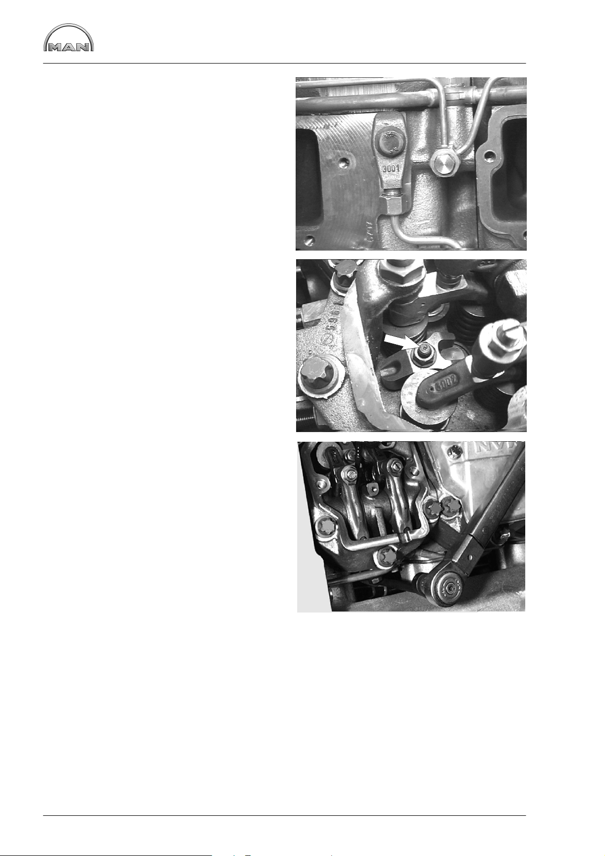
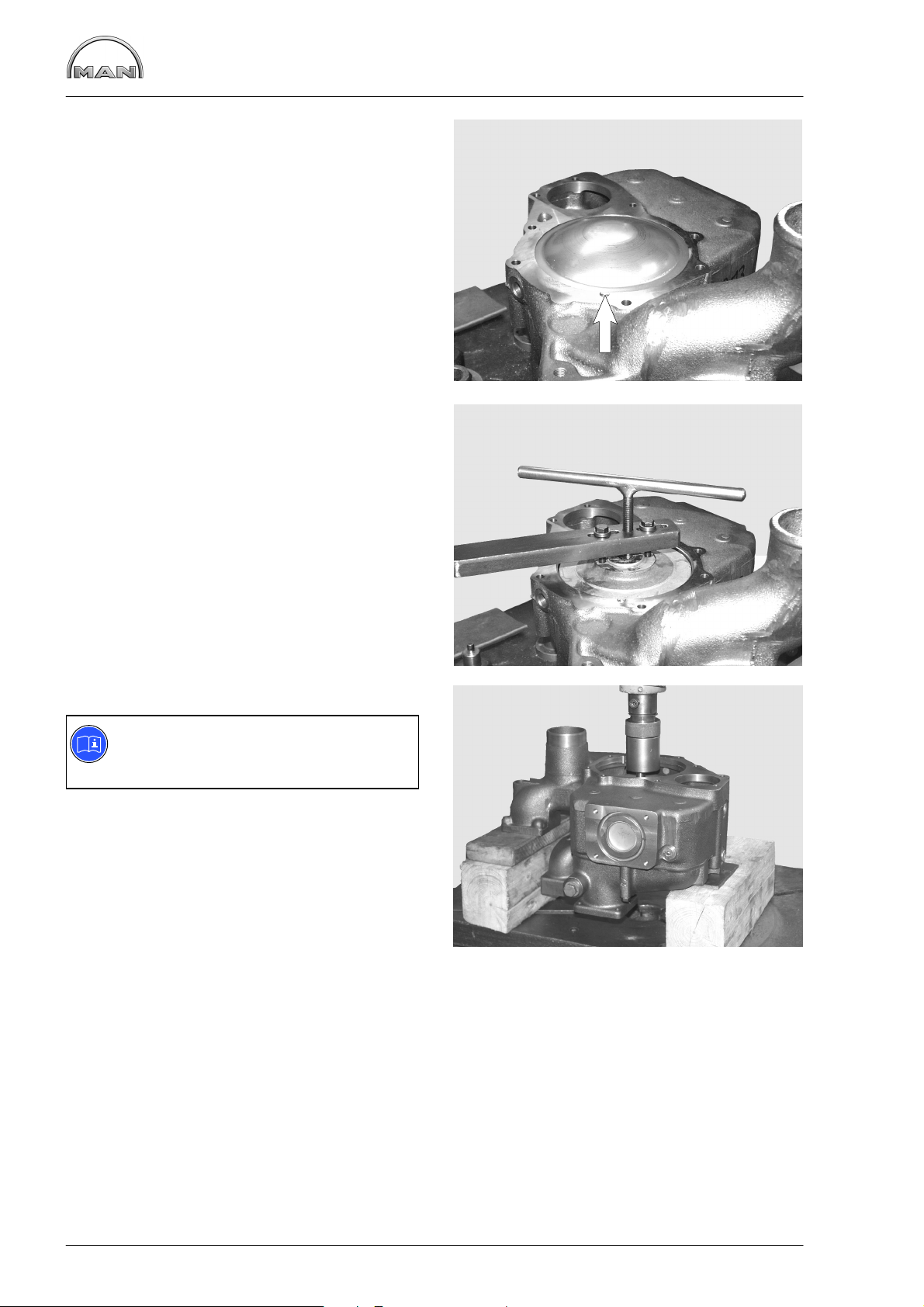
Remove screw plug À on governor housing.
If fitted, take out blocking pin Á.
Caution:
If the injection pump is blocked the camshaft must on no account be loaded or
turned because parts of the blocking pin
may break off and fall into the governor.
Non-compliance with this may result
in severe damage to the injection
pump.
If the pointer is exactly in the centre of the inspection hole, the pump plunger for cylinder no. 1 is at
start of delivery. However, it is possible to determine exactly whether or not the pump is at start of
delivery only by means of the following special
tools:
1. Light signal transmitter
Fig. 6
Push light signal transmitter into socket in governor housing. Ensure that the lug fits in the groove.
Tighten the knurled nut by hand.
Turn engine by hand so that piston in cylinder no.
1 in the compression stroke comes close to the
start of delivery.
Lamp (A) comes on shortly before start of delivery
is reached.
5
6
Fig. 7
Slowly turn the engine further until lamp (B) comes
on too. The injection pump is now at start of
delivery.
Note:
If only lamp (B) comes on during this
test, the engine has been turned past the
start of delivery. In this case turn the engine back and repeat the procedure.
If only lamp (B) comes on during this test, the engine has been turned past the start of delivery. In
this case turn the engine back and repeat the procedure.
7
25
Page 28

Checking and adjusting start of fuel delivery
2. Sleeve
Fig. 8
If a light signal transmitter is not available, good
measurement results can also be achieved with a
plug-in sleeve.
The sleeve is to be made of aluminium or steel.
Set engine to start of delivery as described above.
Insert the sleeve into the governor housing up to
the stop.
The start of delivery is set exactly when the pointer
for start of delivery is in the centre of the 3 mm
bore in the sleeve.
29
ø15
ø12
ø9
13
30
15
ø3
8
ø11
26
Page 29

Checking and adjusting start of fuel delivery
Adjusting start of delivery
If the check according to method 1) or 2) should
prove that the delivery start is not correct, proceed
as follows:
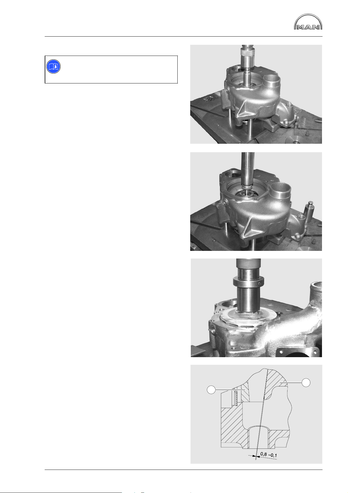
Remove timing case cover.
Fig. 9
Loosen all bolts fastening the drive gear to the injection pump hub. For this, two complete turns of
the engine are necessary.
Fig. 10
Turn engine to specified angle for delivery start.
Remove cylinder head cover from cylinder no. 6
(flywheel end). When the values of this cylinder
are in crossover, the piston in cylinder no. 1 is at
ignition TDC.
Remove screw plug from governor housing (see
Fig. 5). The delivery start pointer must be visible in
the centre of the inspection hole.
Fit a socket wrench to the mounting bolts and turn
the injection pump camshaft at the drive flange to
the left or right until the conditions stated under 1)
or 2) (depending on test method) are met.
10
9
1
2
Fig. 11
Tighten bolts for fastening drive gear to drive
flange consecutively to 5 Nm and then to 30 Nm.
Check delivery start once again.
Install timing case cover.
11
27
Page 30

Removing and Installing Injection Pump
Removing injection pump
Fig. 1
On the injection lines, remove the union nuts at the
injection nozzles and at the injection pump.
Detach all connections for fuel and EDC from the
injection pump.
Caution:
The lines contain fuel!
Catch escaping fuel in a suitable container.
After removal of the injection lines we recommend
fitting caps to the connections on the injection
nozzles and injection pump.
This prevents dirt from getting into the injection
system.
Caution:
Dirt in the injection system causes:
D nozzles to jam
D the injection pump drive to break
Fig. 2
Remove holders (arrow) from injection pump.
Unscrew the mounting bolts from the injection
pump flange.
Fig. 3
The engine-side mounting bolts are difficult to
access.
Use the following special tools here:
1
2
3
2
1
À Cardan universal joint
Á Extension
 Socket wrench
Take off injection pump.
Caution:
The injection pump is heavy!
Use lifting gear.
3
28
Page 31

Removing and Installing Injection Pump
Installing injection pump
Fig. 4
Caution:
If the injection pump is blocked, the camshaft must on no account be loaded or
rotated because parts of the blocking pin
may break off and drop into the governor.
Failure to comply with this instruction
may result in serious damage to the
injection pump!
Remove screw plug À on governor housing.
If fitted, take out blocking pin Á.
Fig. 5
Check whether the engine is at start of delivery.
Start of delivery see “Service Data”.
1
4
2
Fig. 6
Check whether the injection pump is at start of delivery. Remove screw plug from governor housing
(fig. 4). The start of delivery pointer must be visible
in the centre of the inspection hole.
Release the mounting bolts on the injection pump
drive gear so that it can be turned in the elongated
holes.
Hold the injection pump camshaft in place while
turning the gear.
Fit a new O-ring (lightly oiled) on the injection
pump flange.
Insert the injection pump and tighten the mounting
bolts to specified torque.
Fig. 7
Provisionally tighten all the mounting bolts of the
gear through the inspection hole to 5 Nm. Two
complete engine revolutions are necessary for this.
Now tighten down all the mounting bolts to 30 Nm.
5
6
Check and if necessary set start of delivery (see
page 24).
Install timing case cover.
7
29
Page 32

Removing and Installing Injection Nozzles
Removing injection nozzles
Fig. 1
Remove injection lines À.
Unscrew mounting bolts of the connecting piece Á.
Fig. 2
Remove connecting piece Á.
1
1
1
Fig. 3
Pull the pressure pipe  out of the cylinder head.
Fig. 4
Remove cylinder head covers.
2
3
2
3
3
The injector nozzle of the first cylinder is equipped
with a needle movement sensor. Unscrew holder
for cable (arrow).
4
30
Page 33

Removing and Installing Injection Nozzles
Fig. 5
Remove the cover gasket with cable lead-through
À, unscrew mounting clamp Á.
Fig. 6
Unscrew the mounting bolt À of the pressure
flange (see item Á) and remove the pressure
flange.
Take off centring washer and pressure flange.
2
1
5
1
6
2
31
Page 34

Removing and Installing Injection Nozzles
Extractor for injection nozzles
Fig. 7
Extractor tube for injector nozzles (special tools,
see item. 26.1, page 169).
À Knurled nut
Á Extractor with slit for the passage of the cable
for the needle movement sensor
 Bridge
Fig. 8
1 2 3
7
Thread the needle movement sensor through the
extractor tube slit Á and up the connector up
through the tube.
Screw the extractor tube onto the injection nozzle.
Fig. 9
Place bridge À over the extractor tube.
The bridge rests on the cylinder head bolts.
Screw on knurled nut Â.
2
8
1
3
Fig. 10
Withdraw the injection nozzle by turning the
knurled nut.
Clean the nozzle seat in the nozzle bushing.
9
10
32
Page 35

Removing and Installing Injection Nozzles
Installing injection nozzles
Fig. 11
Insert new O-ring À and new copper sealing
ring Â.
Grease the O-ring.
Fig. 12
Insert the injection nozzle into nozzle bushing  so
that inlet hole Á (see also item Á in Fig. 11) points
to the hole for pressure pipe À in the cylinder
head.
Press in the injection nozzle by hand as far as it
will go.
1
2
3
11
1
Fig. 13
Fit pressure flange and provisionally tighten
mounting nut to 10 Nm.
Fig. 14
Insert pressure pipe into the cylinder head.
Caution:
The thin end of the pressure pipe points
towards the injection nozzle.
12
13
2
3
Replace the O-ring and apply a light coating of
grease.
Insert the connection piece and align it so that the
injection line can be connected without tension.
Apply initial torque of 10 Nm to injection line.
14
33
Page 36
Removing and Installing Injection Nozzles
Fig. 15
Apply initial torque of 10 Nm to mounting bolt on
connection piece.
Fig. 16
Tighten the mounting nut of the pressure flange
(arrowed) first to 25 Nm and then to an angle of
90_.
Then tighten connection piece to 20 Nm and afterwards tighten it using a 90_ torque wrench.
15
Fig. 17
Secure the injection line .
Initial installation:
Angle tightening: 60_. . . . . . . . . . . .
Subsequent installation:
Angle tightening: 30_. . . . . . . . . . . .
Afterwards tighten the mounting nut on the compression flange.
Angle tightening: 45_. . . . . . . . . . . . . . . . . . . . . . . . .
Let engine warm up
Angle tightening: 90_. . . . . . . . . . . . . . . . . . . . . . . . .
16
17
34
Page 37

Removing and Installing Injection Nozzles
Check tightness of nozzle holder base,
pressure pipe and leak-oil line
Caution:
After the injection nozzles have been installed, always check to ensure that the
nozzle holder seat, pressure pipe and
leak−off oil lines do not leak.
Fig. 18
À Adapter for connecting up the compressed air
hand pump (to make yourself)
Á Compressed air hand pump with pressure
gauge, special tool, see item. 25, page
LEERER MERKER.
Fig. 19
Make adapter item À, fig. 19 from standard parts
1
2
18
1
À T-connector for connecting up a pressure
gauge with internal thread M8x1, is not necessary if the compressed air hand pump with
pressure gauge item Á, fig. 18 is used and it
must be closed
Á Union nut M16x1,5
 Connector M14x1,5
à Adapter GE 8-PLR 1/4”
Ä Connector fitting for compressed air hand pump
(ewo, part-number 320.031)
Fig. 20
Proceed as follows:
D Loosen injection lines on the connector fitting or
on the injection pump
D Close fuel feed, e.g. on fuel pre-cleaner with
taper plug VKA10
D Connect compressed air hand pump to fuel re-
turn (arrow) with screw connector
D Pump approx. 2 bar pressure to fuel system
19
20
5
234
Caution:
The pressure must not drop for a period
of 3 minutes.
D Tighten up the injection lines again with the
specified torque, see page 34.
D Reconnect leakage fuel return line
35
Page 38

Checking Injection Nozzles
Checking injection nozzle
Fig. 1
The nozzle tester (hand tester) is used to check
the
−− opening pressure (injection pressure),
−− leak-tightness and
−− spray pattern of each injection nozzle.
Use pure calibrating oil or pure diesel fuel for the
test.
Prior to testing, clean the nozzle and check it for
wear.
Check the nozzle with its nozzle holder.
Danger:
The high injection pressure can cause
serious injury. Do not place hands under
the jet spray.
Wear safety goggles.
1
1 2
Fig. 2
À Testing device
Á Inlet connection
Fig. 3
Feed the needle movement sensor cable through
the testing device.
Fig. 4
Insert the injection nozzle with inlet hole À towards
the guide tube for pressure pipe Á in the testing
device.
2
3
1 2
36
4
Page 39

Fig. 5
Checking Injection Nozzles
Insert the pressure pipe with edge-type filter À into
the guide tube.
Note:
The thin end of the pressure pipe points
towards the injection nozzle.
Screw inlet connection Á into the guide tube and
tighten up.
Fig. 6
Connect the pressure line of the tester to the injection nozzle inlet connection.
1
5
2
6
37
Page 40

Cleaning fuel prefilter
Figs. 1 and 2
Fuel Prefilter
Strip the fuel prefilter À:
D Unscrew knurled nut of prefilter
D Swing out retaining arm and take out filter hou-
sin  with strainer filter Á
D Clean filter housing and strainer in clean die-
sel fuel and blow out with compressed air
D Re-assemble in reserve order
D Switch on EDC (if EHAB is fitted)
D Operate the plunger on the hand pump until the
overflow valve in the injection pump can be
heard to open
D Screw in and tighten the hand pump plunger
D Start the engine
D Check the fuel prefilter for leaks
3
1
2
1
Cleaning fuel prefilter
Figs. 3 and 4
Strip the fuel prefilter:
D Remove filter housing À
D Wash out filter housing À and gauze filter
clean Diesel fuel and blow them out with com-
pressed air
D Reassemble with a new seal
D Screw on filter housing and tighten it to 10 − 12
Nm
D Actuate tappet of hand primer until overflow
valve of injection pump is heard to open
D Screw in and tighten the hand pump plunger
D Start the engine
D Check the fuel prefilter for leaks
Á in
2
21
3
38
4
Page 41

Fuel prefilter with water separator
Fig. 5
Draining water:
D Open drain screw À and let off water.
D Close drain screw À again
Fuel Prefilter
Changing filter element
Only when the engine is swiched off.
D Remove inspection glass Á and filter element Â
D Wet seal on new filter with fuel
D Screw on filter  and inspection glass Á by
hand
D After this, bleed the fuel system
D Check the filter for leaks
Caution:
Used fuel filters are classed as dangerous waste and must be disposed of accordingly.
3
2
1
5
39
Page 42

Removing and attaching fuel filter, exchanging filter cartridge
Changing fuel filter
Only when the engine is swiched off.
Figs. 1 and 2
D Remove filter cartridge using tape wrench.
D Wet seal on new filter with fuel
D Screw on filter by hand
D After this, bleed the fuel system
D Check the filter for leaks
Caution:
Used fuel filters are classed as dangerous waste and must be disposed of accordingly.
1
Bleeding the fuel system
Figs. 3 and 4
Note:
To bleed the fuel system switch on the
“ignition” so that the EHAB will be open.
An arrow on the filter head indicates the direction
of fuel flow.
D Unscrew the vent screw of the first filter in the
direction of flow by one or two turns
D Actuate tappet of hand primer until fuel emer-
ges without bubbles
D Screw in and tighten the hand pump plunger
D Close bleed screw
D Repeat this procedure at the second bleed
screw
D Check the filter for leaks
2
3
40
4
Page 43

Flame starter sheathed-element glow plug,
removing and installing
Removing sheathed-element glow plug
Fig. 1
Disconnect the electric connections from the sheathed-element glow plug.
Remove fuel line carefully.
Loosen counter nut on sheathed-element glow
plug and remove glow plug.
Installing sheathed-element glow plug
Fig. 2
Turn counter nut on sheathed-element glow plug
upwards until it stops.
Screw in sheathed-element glow plug with “Hylomar” until it stops at the counter nut and align it
with fuel line.
1
Connect up fuel line and electric connection.
Tighten counter nut.
Checking solenoid valve for leaks
Remove fuel line from flame glow plug.
When the engine is running and hot, no fuel must
emerge.
Removing solenoid valve
Fig. 3
D Remove fuel lines
D Remove electric connection from valve
D Remove the two hex bolts and take off valve
The valve cannot be repaired.
Exchange the defective valves.
Fitting solenoid valve
D Screw valve to holder
D Screw on electric connection
D Fit the fuel lines with new sealing rings
2
3
Note:
For detailed description see
“EDC repair manual”.
41
Page 44

Draining and filling coolant
Draining coolant
Danger:
When draining hot coolant, there is a
danger of scalding!
Drain coolant as follows when cooling system has
cooled down
Note:
Collect the drained coolant and dispose
of it in accordance with regulations!
To drain the coolant open one or both of the drain
plugs (arrows). There is a further drain plug on the
coolant elbow in the exhaust-gas recirculation system; use a container of sufficient size to catch the
coolant.
Catch emerging coolant in a suitable container.
Fill / bleed the cooling system (only when engine has cooled down)
The cooling system of the engine is to be filled with a mixture of drinking water from the mains and antifreeze based on ethylene glycol and/or anticorrosion additive.
See Publication “Fuels, Lubricants and Coolants for MAN Diesel Engines”.
Coolant must be poured in according to the vehicle manufacturer’s filling specifications.
Do not pour any cold coolant into an engine which is still warm.
Ensure that the ratio of water to anti-freeze is correct.
D Pour in coolant slowly until the correct coolant level is reached (max. 10 ltr./min.)
D Open the drain plug on the coolant elbow in the exhaust−gas recirculation system and bleed the ex-
haust-gas recirculation module
D Run the engine briefly and then check coolant level once more
Danger:
If, in exceptional cases, the coolant level on warm engines has to be checked or the cooling circuit
opened, observe the vehicle manufacturer’s safety regulations.
42
Page 45

Removing and Installing Thermostats
Note:
If the thermostat is fitted to the outside,
short-circuit inserts instead of thermostat
inserts are installed in the engine.
D Drain off coolant, see page 42
Remove the three mounting bolts from coolant
neck À and take off coolant neck.
Take out thermostats.
Check the function of the thermostat insert as
follows.
D Suspend the thermostat in a bowl of water
D Heat up the water
D Using a suitable thermometer, ascertain the
start of opening and compare it with the setpoint value in “Service data”
D If necessary, measure the opening stroke
1
Replace defective thermostats.
Install thermostat inserts with ball valve facing upwards (TOP) with new O-ring À and new seal Á.
Caution:
Never let the enging run without thermostats or short-circuit inserts.
43
Page 46

Removing and installing the engine coolant pump
Removing coolant pump
D Draining off coolant, see page 42
D Remove the thermostats, see page 43
Take V-belt off
Fig. 1
Remove al bolts from the hub.
Fig. 2
Release the coolant pump mounting bolts and remove the coolant pump.
Clean the sealing faces on coolant pump and engine housing.
, see page 133.
1
2
44
Page 47

Removing and installing the engine coolant pump
Instaling coolant pump
Fig. 3
Renew O−ring.
Fit coolant pump with new seal.
Tighten the securing bolts with the prescribed torque.
Fig. 4
Refit V-belt pulley and coolant neck.
Insert thermostat insert, see page 43.
Fit and tension the V-belt see Page 134.
3
Fill coolant, see page 42
Note:
Exchange or repair coolant pump only if it has been found to be leaky.
The design of the coolant pump mechanical cassette seal permits small amounts of coolant to
pass through it. This coolant passing through results in a trace of drained coolant below the drain
bore. The coolant pump need not be exchanged or repaired because of this trace of permeating
coolant.
For this reason, before replacing or repairing a coolant pump, ascertain
D whether the cooling circuit shows visible and recurring signs of coolant loss; if yes
D whether the coolant loss is caused by spillage from the expansion tank (e.g. too full) or by
other leakages from hoses, radiator etc.
Coolant pumps must be exchanged only if water drips visibly while the engine is in operation or
after the engine has been switched off.
4
45
Page 48

Repairing engine coolant pump
Fig. 1
À Pump housing
Á Impeller
 Cap
à Mechanical seal
Ä Coolant pump bearing
Å Hub
Æ Circlip
Removing the coolant pump, see page 44
Disassembling coolant pump
Fig. 2
Clamp coolant pump in vice (using soft jaws).
Pull off V-belt pulley with three-arm puller.
1
2
3
4
5
6
7
1
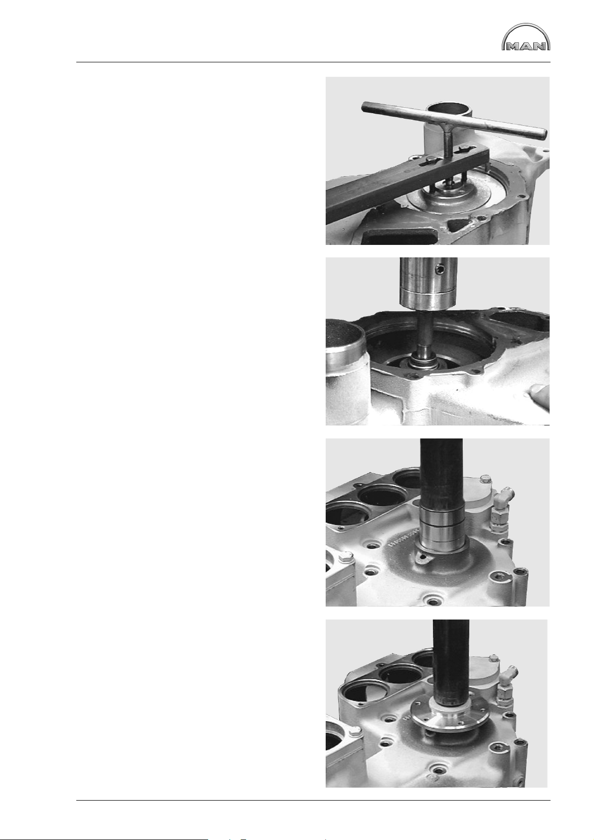
Fig. 3
Unclip the circlip from the coolant pump housing.
Fig. 4
Knock out cover by driving a suitable mandrel under it (Fig. 1, item Â) at notch (arrow).
2
3
46
4
Page 49
Repairing engine coolant pump
Fig. 5
Pull impeller off the coolant pump bearing.
For this purpose four M8 threaded bores are provided.
Fig. 6
Align water pump housing on a suitable and stable
surface.
Use suitable mandrel to press the coolant pump
shaft with bearing out of the housing.
Shaft and bearing are encapsulated and replaced
as a single unit only.
5
Take off axial face seal.
Reassembling coolant pump
Fig. 7
Press in coolant pump bearing.
For this purpose use suitable pressing die to ensure that pressure is applied to the bearing outer
ring and not to the bearing shaft.
Fit the circlip.
Fig. 8
Press boss flush on to bearing shaft.
6
7
47
8
Page 50

Repairing engine coolant pump
Fig. 9
Turn water pump housing over and Press in new
mechanical seal with press-fitting sleeve (special
tool) until it stops.
Observe installation note for seal on page 50.
Note:
The seal can be exchanged even without
removing the coolant pump shaft.
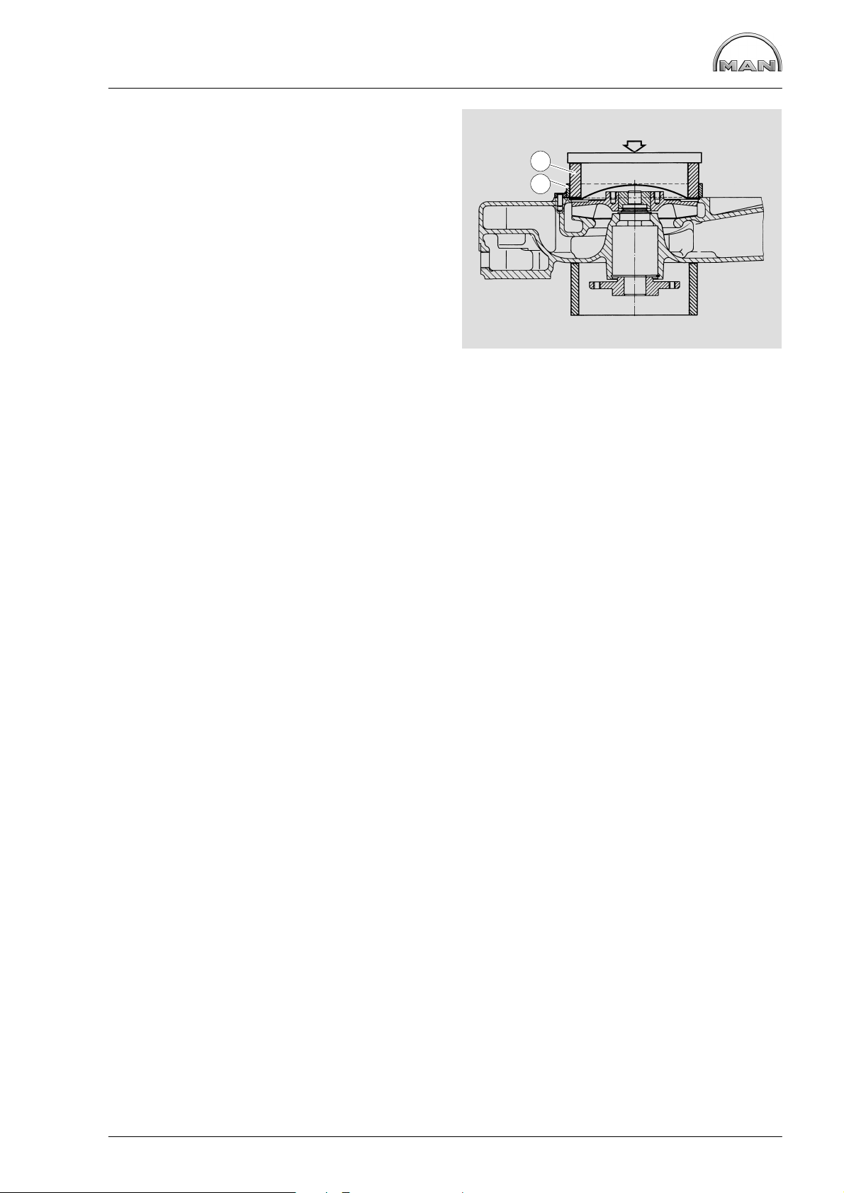
Fig. 10
Press impeller slowly on to bearing shaft to ensure
correct gap.
9
Fig. 11
For this purpose an inspection hole closed up with
a screw plug (M16x1.5) is provided on the bottom
of the coolant pump housing.
À Impeller
Á Coolant pump housing
Fig. 12
Fit new pump cover and press it into housing,
using a suitable pressing tool.
10
2
1
0,5+0,2
11
12
48
Page 51
Repairing engine coolant pump
Fig. 13
If no suitable pressing tool is available, you may
use self-made special tools (see chapter “Special
tools”) and proceed as follows:
D Align guide ring Á with the two dowel pins on
the pump housing
D Insert pressing ring À into guide ring
D Place a flat steel (min. thickness: 10 mm) on
the pressing ring
D Press cover into housing using a press
Fit coolant pump with new gasket,
see page 44.
1
2
13
49
Page 52

Repairing engine coolant pump
Replacing coolant pump during repair work only in event of identified leakage
The design of the coolant pump mechanical cassette seal permits small amounts of coolant to pass
through it.
This coolant passing through results in a trace of drained coolant below the drain bore.
This trace of drained coolant does not mean that the coolant pump has to be replaced.
For this reason before exchanging or repairing a coolant pump ascertain
D whether the cooling circuit shows visible and recurring signs of coolant loss; if yes
D whether the coolant loss is caused by spillage from the expansion tank (e.g. too full) or by other leaka-
ges from hoses, radiator etc.
Coolant pumps may only then be replaced if dripping water can clearly be seen while the engine is running
or after it has been turned off.
Installation note for mechanical seal
Fit the mechanical seal “wet”, i.e. when fitting, coat holding sleeve à and coolant pump shaft À with a mixture of 50% water and 50% cleaning spirit or 40% to 50% antifreeze as per MAN 324 and water.
Other antiseize agents must not be used.
Because the seal on collar Á is coated with sealing paint, no sealing paint needs to be applied if the locating bore in the coolant pump housing is in perfect condition.
If the bore shows even the slightest scoring or other minor damage, a sealing bead of Dirko-Transparent,
Part No. , must be applied to collar Á.
Fit the seal with a plastic transportation cap onto shaft À and use installation tool Ä to press it in until the
tool contacts the housing. Remove the plastic cap.
1 2 3 4
5
Note:
Tests have shown that most cases of damage to the coolant pump can be attributed to the use of
unsuitable coolants.
Only the anticorrosion and antifreeze agents expressly approved by MAN Nutzfahrzeuge AG as
per MAN norm 324 (see brochure “Fuels, Lubricants, Coolants for and MAN Diesel Engines”) guarantee faultless operation
50
Page 53

Repairing coolant pump with high-temperature and
low-temperature parts
Coolant pump for three thermostats
Fig. 1 and 2
À Pump housing HT (high-temperature part)
Á Pump housing LT (low-temperature suction
part)
 Hub
à Bolt DIN 931−M8x155, hex nut DIN 934−M8
Ä Bolt DIN 933−M8x358.8
Å Mechanical seal 51.06520−0085
Æ Impeller for coolant pump, HT circuit
Ç Mechanical seal 51.06520−0099
È Counterring complete 51.06520−0100
É Impeller for coolant pump, LT circuit
11
Splash shield
12
Mechanical seal 51.06520−0096
13
Coolant pump bearing
14
Drive shaft for coolant pump
15
Circlip
16
Coolant pump seal
17
Grooved ball bearing 6003
18
Cap
1
2
3
5
4
1
18
6
7
17
8
9
10
11
16
12
13
Disassembling coolant pump
Fig. 3
Removing the water pump, see page 44
Clamp water pump in a vice, use protective jaws.
Pull off boss with three-arm puller.
Fig. 4
Unclip the circlip from the coolant pump housing.
15
2
3
14
51
4
Page 54
Repairing coolant pump with high-temperature and
low-temperature parts
Fig. 5
Knock out cover by driving a suitable mandrel
under it (Fig. 2, item 18) at notch (arrow).
Fig. 6
Pull impeller off coolant pump shaft.
For this purpose four threaded bores M8 are provided.
5
Fig. 7
Note:
Remove bolt from low-temperature part
(Fig. 1, item 5).
Align water pump housing on a suitable and stable
surface.
Use a suitable mandrel to press the water pump
shaft together with bearing out of the housing.
Take off mechanical seal.
The high-temperature part and the low-temperature suction part are now separated.
Remove axial face seals and grooved ball bearing
from high-temperature part if they are still in the
housing.
6
7
52
Page 55

Repairing coolant pump with high-temperature and
low-temperature parts
Reassembling coolant pump
Fig. 8
Press in water pump bearing.
Fit the circlip.
Note:
If you change the seals always install a
new shaft and axial face seals.
Fig. 9
Press boss flush on to bearing shaft.
Use suitable plates (80.99614−0027 and
80.99606−0628) to brace the bearing shaft.
8
Fig. 10
Turn coolant pump over (for this support bearing
shaft with 80.99606−0629) and press in new axial−
face seal (Fig. 1, no. 12) using mandrel
(80.99606−0252) until mandrel is in contact.
Observe installation note for seal on page 57.
Fig. 11
Press in counterring (arrow) with a suitable pressing tool (may be possible by hand).
Install mechanical seal while “wet”, i.e. to install it,
coat holding sleeve and water pump shaft with a
mixture of either 50% water and 50% cleaning
spirit or 40% to 50% antifreeze agent as per MAN
324 and water.
9
10
11
53
Page 56

Repairing coolant pump with high-temperature and
low-temperature parts
Fig. 12
Note:
Brace the bearing shaft.
Press impeller slowly on to bearing shaft (mandrel
80.99604−0252) to ensure that the correct gap
+0,4
(0,5
Fig. 13
Press axial−face seal (no. 8) into pump housing
(no. 1) using pressing tool (80.99606−0252).
Observe installation note for seal on page 57.
) is achieved.
12
Fig. 14
Lay coolant pump gasket on pump housing.
Fig. 15
Carefully fit low-temperature suction part to high−
temperature pump housing.
To make assembly easier insert 2 pins in opposite
sides of HT part (see Fig. 14)
Do not use force (hammer etc.) and note the 3
centring features (see arrows in Fig. 14).
13
14
Screw in bolt (Fig. 1, item 1).
Bolt LT and HT parts together with 2 bolts and nuts
on opposite sides (Fig. 1, item 4).
15
54
Page 57
Repairing coolant pump with high-temperature and
low-temperature parts
Fig. 16
Note:
For subsequent steps brace the bearing
shaft.
Press grooved ball bearing 6003 into position using
special die (80.99604−0254).
Fig. 17
Press axial-face seal (no. 6) into pump housing
(no. 1) using pressing tool (80.99617−0191).
Observe installation note for seal on page 57.
16
Fig. 18
Slowly press impeller on to bearing shaft to ensure
correct gap.
Fig. 19
For this purpose an inspection hole closed up with
a screw plug (M16x1.5) is provided on the bottom
of the coolant pump housing.
À Impeller
Á Coolant pump housing
17
18
2
1
19
55
Page 58

Repairing coolant pump with high-temperature and
low-temperature parts
Fig. 20
Fit new pump cover and press it into housing,
using a suitable pressing tool.
Fit coolant pump with new gasket, see page 44.
20
56
Page 59

Repairing coolant pump with high-temperature and
low-temperature parts
Replacing coolant pump during repair work only in event of identified leakage
The design of the coolant pump mechanical cassette seal permits small amounts of coolant to pass
through it.
This coolant passing through results in a trace of drained coolant below the drain bore.
This trace of drained coolant does not mean that the coolant pump has to be replaced.
For this reason before exchanging or repairing a coolant pump ascertain
D whether the cooling circuit shows visible and recurring signs of coolant loss; if yes
D whether the coolant loss is caused by spillage from the expansion tank (e.g. too full) or by other leak-
ages from hoses, radiator etc.
Coolant pumps may only then be replaced if dripping water can clearly be seen while the engine is running
or after it has been turned off.
Installation note for mechanical seal
Fit the mechanical seal “wet”, i.e. when fitting, coat holding sleeve à and coolant pump shaft À with a mixture of 50% water and 50% cleaning spirit or 40% to 50% antifreeze as per MAN 324 and water.
Other antiseize agents must not be used.
Because the seal on collar Á is coated with sealing paint, no sealing paint needs to be applied if the locating bore in the coolant pump housing is in perfect condition.
If the bore shows even the slightest scoring or other minor damage, a sealing bead of Dirko-Transparent,
Part No. , must be applied to collar Á.
Fit the seal with a plastic transportation cap onto shaft À and use installation tool Ä to press it in until the
tool contacts the housing. Remove the plastic cap.
1 2 3 4
5
Note:
Tests have shown that most cases of damage to the coolant pump can be attributed to the use
of unsuitable coolants.
Only the anticorrosion and antifreeze agents expressly approved by MAN Nutzfahrzeuge AG as
per MAN norm 324 (see brochure Fuels, Lubricants, Coolants for and MAN Diesel Engines”)
guarantee faultless operation
57
Page 60

Cleaning cooling system
Cleaning the inside of the cooling system
Note:
Co-ordinate cleaning measure with radiator manufacturer beforehand!
Investigations have shown that in many cases the poor condition of the coolant and / or the cooling system
accounts for damage to the water pump mechanical seal. The poor condition of the cooling system is normally due to use of unsuitable or no anti-freezing agents and corrosion inhibitor or defect, not early enough
replaced covers for filler neck and working valves.
If twice in a short time the water pump of an engine develops leakes or the coolant is heavily contaminated
(dull, brown, mechanically contaminated, grey or black signs of a leakage on the water pump casing, after
the defect on the oil cooler) clean the cooling system prior to removing that water pump as follows:
a) Drain coolant
b) Open thermostats positively (use short-circuit inserts), so that the entire coolant circuit is flushed in the
cleaning operation
c) Fill coolant circuit with a mixture of hot water (min. 50°C) and Henkel P 3 neutrasel 5265 detergent
(1.5% by volume) (-5266, -5225, Kluthe Hakopur 316), refer to Publication “Fuels, Lubricants ...”
d) Warm up engine under load. After a temperature of 60°C is reached, run engine for a further 15 minutes
e) Drain cleaning fluid
f) Repeat steps c) and d)
g) Flush cooling system. To this effect
h) Replace drain plug by drain plug with a bore of 8 mm dia
i) Fill cooling system with hot water
k) Run engine at idle for 30 minutes. At the same time continuously replenish the water leaking from the
bore in drain plug by adding fresh water
Repair water pump only now. Thereafter, fill the cooling system with approved cooling fluid. See Publication
“Fuels, Lubricants ...”.
Note:
Only sediments and suspended particles can be removed by this cleaning method. If corrosion
and lime deposits are found, proceed according to the following section:
58
Page 61

Cleaning cooling system
Removal of lime deposits in the cooling system
Note:
Co-ordinate decalcifying measure with radiator manufacturer beforehand!
Procedure:
D Drain the coolant
D Fill the system with undiluted original pickling fluid (Engine pickling fluid RB-06), see sources of supply
D Let the engine run (also in normal operation) for approx. 8 hours with this filling in the cooling circuit
D Drain the pickling fluid and thoroughly flush the system with tap water
D If necessary, refill the circuit again with fresh pickling fluid and pickle the engine for another 8 hours
D Drain the pickling fluid, fill the system with tap water, and run the engine at idle for 5 minutes to flush out
all fluid; then drain the water
D Fill the system with a 1% soda solution. Drain the soda solution after running the engine at idle for
5 minutes, and flush with tap water until the discharging water is clear
D Fill cooling circuit with a mixture of potable tap water and anti-freeze with at least 40% by volume,
refer to Publication “Fuels, Lubricants ...”
Note:
Older radiators may develop leaks when such deposits are removed. The surge tank should be
filled only up to the bottom edge as otherwise foaming will cause the pickling fluid to spill over.
Damaged tube bundles may develop leaks when dirt deposits are removed.
Filler caps and working valves of cooling system
The rubber gaskets of the filler caps and working valves (negative pressure and positive pressure valves)
of the cooling system are subject to natural aging.
To preclude leakages in the cooling system and tailing pressure drop and its consequences up to severe
engine damage, renew the filler caps and working valves in line with the change of coolant (every two years
at the latest) see also “Filling-in of coolant” in this chapter.
Waste water treatment
Drained and spent cleaning and pickling fluid should be brought up to a pH value of 7.5 to 8.5 with the aid
of caustic soda. Once the precipitation has settled to the bottom of the container the clear fluid above can
be dumped into the sewer. The sludge at the bottom should be taken to a special waste dump. Anyway, it
is recommended to consult the local authorities for more information about waste water rules or restrictions.
Sources of supply for pickling fluids
Motor pickling fluid RB−06
Reincolor-Chemie GmbH
Werkstr. 21
D−90518 Altdorf
Phone: (0 91 87) 97 03 0
59
Page 62

Changing the oil filter
Caution:
Old oil and used oil filters are hazardous
waste.
Observe safety instructions for the prevention of environmental damage.
Fig. 1
Open the oil drain plug on the oil filter casing and
catch emerging oil in a suitable container.
Danger:
The oil filter casing and filter insert are
filled with hot oil; danger of burns and
scalding!
Reinsert oil drain plug with new gasket.
Fig. 2
Loosen the securing bolt of the filter cup.
Remove filter cup and clean inside.
Fig. 3
Insert a new filter cartridge and reinstall the filter
casing with new seals.
Observe tightening torque for securing screw.
Note:
To avoid twisting the gasket, hold the
filter cup while tightening the tensioning
screw.
1
2
Fill engine oil and check for leaks after a short engine run
Check oil level.
3
60
Page 63

Removing and installing the oil cooler
Removing the oil cooler
Caution:
Old oil is hazardous waste.
Observe safety instructions for the prevention of environmental damage.
Fig. 1
Oper oil drain plug and use container to catch the
oil that may emerge.
Use a vessel of sufficient size to ensure that the oil
does not overflow.
Danger:
The oil is hot− risk of scalding. Do not
touch the oil drain plug with bare fingers.
Oil is an environmental hazard. Handle it
with care!
1
D Draining off coolant, see page 42
D Remove oil filter, see page 60
Fig. 2
Unscrew the mounting bolts from the oil cooler
housing.
Remove the oil cooler housing together with the oil
cooler.
Fig. 3
Remove the oil cooler from the housing.
Fig. 4
2
3
Inspect the oil cooler for damage and replace if
necessary.
Fit oil cooler with new gaskets.
4
61
Page 64

Removing and installing the oil cooler
Fig. 5
Take a new o-ring for oil cooler housing.
Screw on oil cooler housing together with attached
oil cooler.
Fig. 6
Tighten the securing bolts with the prescribed torque.
D Attach oil filter with new seals
D Top up engine with oil
D Top up coolant.
5
6
62
Page 65
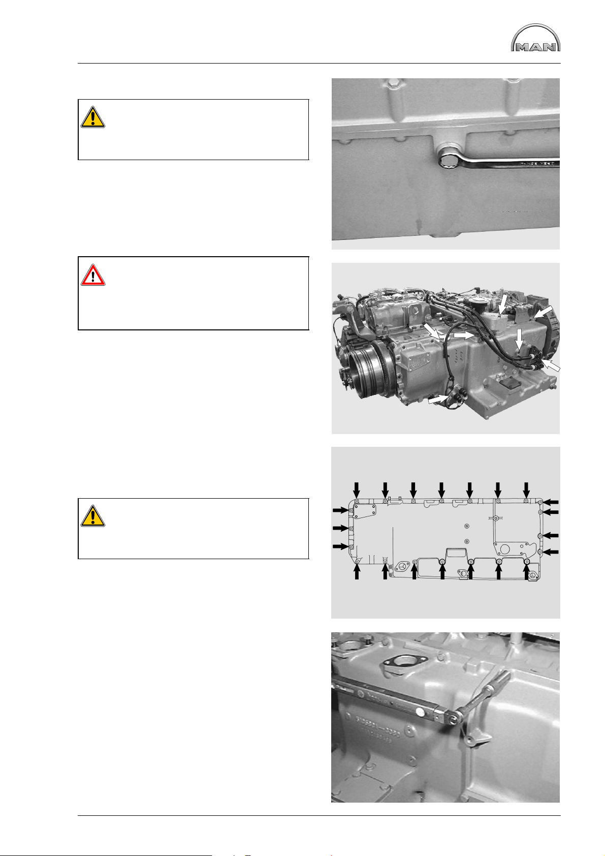
Removing and installing the oil pan
Remove oil pan
Caution:
Old oil is hazardous waste.
Observe safety instructions for the prevention of environmental damage.
Fig. 1
Open oil filler neck.
Remove oil drai plugs and allow the oil to drain off
completely.
Use a vessel of sufficient size to ensure that the oil
does not overflow.
Danger:
The oil is hot− risk of scalding. Do not
touch the oil drain plug with your bare
fingers. Oil is an environmental hazard.
Handle it with care!
1
Fig. 2
Completely remove crankcase breather, the oil
level probes and the oil filler pipe.
Remove bridge for cable harness and move cable
harness to one side.
Fig. 3
Loosen the securing bolts of the oil pan.
Take off oil pan.
Caution:
Oil pans are heavy.
It is now supported only by the lower oil.
Fitting the oil pan
2
3
Fig. 4
Replace the oil pan gasket.
Tighten the securing bolts with the prescribed torque.
4
63
Page 66

Removing and installing the oil pan
Fig. 5
Fit engine cable harness, the bridge for the cable
harness, the oil filler pipe, the oil level probe and
the crankcase breather.
Refit oil drain plugs with new seals.
Fill up the engine oil. Check oil level. Check the oil
pan for leaks
5
64
Page 67

Removing and Installing / Repairing Oil Pump
Removing the oil pump
Drain engine oil from the oil pan and from the oil
filters.
Use a vessel of sufficient size to ensure that the oil
does not overflow.
Danger:
The oil is hot− risk of scalding. Do not
touch the oil drain plug with bare fingers.
Oil is an environmental hazard. Handle it
with care!
Caution:
Old oil is hazardous waste.
Observe safety instructions for the prevention of environmental damage.
D Removing the oil pan, see page 63
Fig. 1
Unscrew the oil intake pipe.
Fig. 2
Remove mounting bolts of pressure relief valve
and the oil pump.
The overpressure valve is encapsulated.
Opening pressure, see “Service Data”.
Remove oil pump.
1
2
65
Page 68

Removing and Installing / Repairing Oil Pump
Servicing the oil pump
Fig. 3
Clamp the oil pump in a vice (use protective jaws).
Remove the oil pump cover.
Fig. 4
Pull the driven oil pump wheel from the casing.
Check the toothed wheels and pump casing for
wear (see “Service Data”).
3
Fig. 5
Remove the oil pump drive gear.
To do this, lay the pump on a suitable surface and
press off the drive gear with a mandrel.
To install, place the drive gear on the shaft, supporting the opposite shaft end in the process.
Press on the drive wheel, observing the prescribed
gap (see “Service Data”).
Fig. 6
Fit the cover.
Tighten the securing bolts with the prescribed
torque.
4
5
66
6
Page 69

Removing and Installing / Repairing Oil Pump
Checking the axial clearance of the
pump wheels
Fig. 7
Attach a dial gauge, push the shaft in one direction
up to the stop and set the dial gauge to “0”.
Press the shaft in the opposite direction and read
off the reaction of the dial gauge.
Axial clearance of pump gears in new condition
see “Service Data”.
7
Fitting the oil pump
Fig. 8
before fitting, check that the oil pump is running
smoothly.
Fit the oil intake line À with seal. Screw on the
pressure-relief valve Á without seal.
Before installing the oil pan, crank the engine to
check whether the crank gear and the oil pumps
run unimpeded and smoothly.
Stick new oil pan gasket on to oil pan using grease
and then bolt oil pan into place.
22 1
8
67
Page 70

Removing and Installing Oil Spray Nozzle
Removing oil spray nozzle
D Drain engine oil
D Removing the oil pan, see page 65
Fig. 1
Unscrew the oil spray nozzle valve (arrowed) and
remove with the oil spray nozzle.
Fig. 2
À Oil spray nozzle valve
Á Oil spray nozzle
Note:
The oil spray nozzles are provided with
balls. When the oil spray nozzle valve is
tightened at the factory, the balls are
pressed into the crankcase where they
make impressions which are used as
marker points for installing the nozzle in
the event of repairs.
1
2
1
2
Checking oil spray nozzle valve
Fig. 3
Use a piece of wire to check whether the valve
piston is easy to move.
Opening pressure, see “Service Data”.
Installing the oil injection nozzle
Fig. 4
Screw in the oil spray nozzle together with its
valve.
The balls of the oil spray nozzle must be located in
the impressions designated for this purpose in the
crankcase. This ensures that the nozzle is secured
in the correct installation position.
Turn the engine. The crankshaft drive or pistons
must not collide with the oil injection nozzle.
3
Tighten the securing bolts with the prescribed
torque.
4
68
Page 71

Removing and fitting vibration damper,
replacing front crankshaft gasket
Remove pilot clutch
Note:
Match−mark the parts and remove them.
Fig. 1
D Disconnect propshaft from clutch and pull it off
D Remove inner bolts À and lift out clutch.
Strip and check pilot clutch; see page 135.
1
Removing vibration damper
D Crank the engine to TDC. This ensures that it is
easier to fit the graduated disc during subsequent assembly work.
D Block the crankshaft drive.
D Relieve tension on the V−belt and remove the
belt.
D Remove the delivery start pointer
Fig. 2
Loosen the securing screws of the vibration damper.
Remove the vibration damper.
Remove oil thrower from the crankshaft.
Note:
Prior to removal mark the position of the
vibration damper relative to the crankshaft. This will ensure that in the subsequent reassembly the graduated disc is in
correct position.
1
2
Caution:
The vibration damper is sensitive to impacts.
69
Page 72

Removing and fitting vibration damper,
replacing front crankshaft gasket
Replacing the front crankshaft gasket
Fig. 3
Loosen the securing screws of the cover.
Fig. 4
Remove the cover.
Only replace the front crankshaft gasket as a complete unit, i.e. replace the bearing race and the
radial shaft sealing ring.
3
Replacing the bearing race
Note:
The engine is not delivered with the
thrust ring as a series feature.
The spare crankshaft seal also contains
the thrust ring.
Fig. 5
A stripping device (special tool) is required to remove the bearing race.
Fig. 6
Pull off the bearing race.
4
5
70
6
Page 73
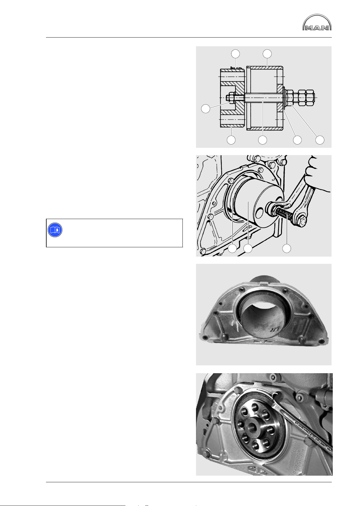
Removing and fitting vibration damper,
replacing front crankshaft gasket
Fig. 7
A special too is required to fit the bearing race.
Clean the inside of the bearing race and tail shaft.
Coat the crankshaft stub with “Antipor 46” sealing
compound.
D Push the bearing race À and press-in sleeve Á
onto adapter Å.
D Tighten spindle Ä in adapter Å with nut Æ
D Screw adapter Å securely onto the crankshaft.
Fig. 8
The adapter must lie free of clearance on the
crankshaft so that the right press−in depth of the
bearing race is ensured.
Pull the bearing race as far as it will go into the
press−in sleeve Á on the adapter with collar nut
and thrust washer ( and à in Fig. 7).
1 2
7
7
4
356
Note:
The bearing race can also be mounted
when the cover is fitted.
Replacing the radial shaft sealing ring
Fig. 9
To ensure perfect installation, the replacement cover and shaft sealing ring are only delivered as a
complete unit.
So that it remains possible to mount the shaft sealing ring, it must stay on the transport and installation sleeve until assembly.
Refer to the comments and assembly instructions
on page 78.
Fig. 10
Fit the cover with a new seal.
8
9
2 51
10
71
Page 74
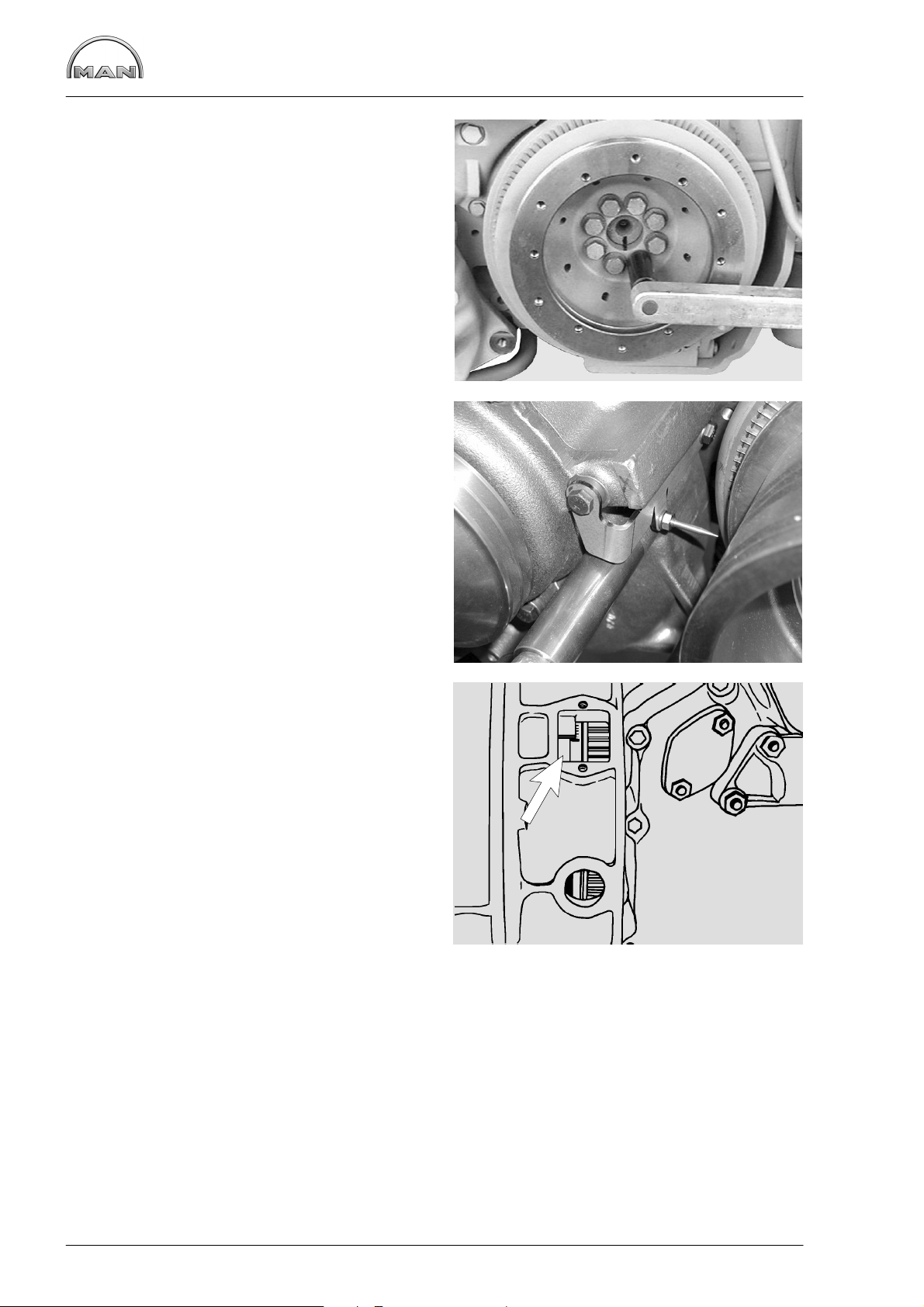
Removing and fitting vibration damper,
replacing front crankshaft gasket
Fitting the vibration damper
Fig. 11
Position vibration damper; note the position of the
scale disc relative to the crankshaft as you do so!
Tighten the securing bolts with the prescribed torque.
Fig. 12
Screw on delivery start indicator.
Refit and tension V-belt, see page 134.
11
Fig. 13
Therefore check whether the scale of degrees on
the inspection hole cover of the flywheel housing
and on the vibration damper indicate the same values.
If necessary readjust delivery start indicator.
12
13
72
Page 75

Removing and fitting vibration damper,
replacing front crankshaft gasket
Fit pilot clutch
Fig. 14
Before assembly clean all clutch parts,
see page 135.
Push pre-assembled clutch on to driver flange and
fasten it with interior bolts (À, 14 Nm).
Reconnect propshaft and clutch.
The positions of the individual parts are marked.
Comply with specified torques.
Caution:
Unblock the crankshaft drive!
1
14
73
Page 76

Removing and installing flywheel,
replacing gear ring
Removing the flywheel
Fig. 1
Release the mounting bolts, securing the engine
against rotating if necessary.
Fig. 2
Unscrew two bolts opposite one another and replace with two guide mandrels (special tool).
Remove all the bolts.
Pull off the flywheel with suitable lifting gear.
1
Danger:
The flywheel is heavy!
Use lifting gear.
Fitting the flywheel
Fig. 3
Insert the guide pins.
Coat the sealing face on the inside of the flywheel
with “Antipor 46” sealing compound.
Place guide mandrels on the flywheel; ensuring
that the centering mandrel (arrow) fits correctly into
the bore in the flywheel.
Push the flywheel on as far as it will go.
Fig. 4
2
3
Lightly oil the new mounting bolts (stress bolts),
screw them in and tighten in diagonal sequence to
specified torque.
4
74
Page 77

Removing and installing flywheel,
replacing gear ring
Replacing starter ring gear
Fig. 5
Remove the flywheel.
Drill the starter motor toothed wheel and break
with a chisel.
Caution:
In doing so, do not damage the flywheel.
Fig. 6
Note:
As the maximum axial run−out of the
starter motor toothed wheel must not be
exceeded, the axial run−out of the flywheel should be measured on the contact
surface of the starter motor toothed
wheel prior to shrinking on the starter
motor toothed wheel.
If the required value is exceeded, replace
the flywheel.
5
Engage the flywheel at the hub.
Apply the dial gauge to the contact surface of the
toothed wheel.
Turn the flywheel a few revolutions by hand and
observe the reaction of the dial gauge.
Fig. 7
Heat the new starter ring gear to approx. 200°C to
230°C and press on as far as it will go.
Danger:
The parts are hot! Risk of burns!
Wear protective gloves.
Check the axial runout and compare with the max.
permissible value.
6
7
75
Page 78

Replacing crankshaft seal
(flywheel end)
Removing shaft sealing ring
Fig. 1
Remove flywheel, see page 74.
Prise out the seal using the special tool (Fig. 2) or
a screwdriver.
Fig. 2
Special tool for levering out the crankshaft gasket.
1
Fit shaft sealing ring
Fig. 3
If the shaft sealing ring on flywheel side is replaced, it is also recommended to replace the bearing
race of the flywheel.
Insert the new shaft seal into the flywheel housing.
Use mandrel (special tool) to drive in sealing ring
until flush.
Refer to the comments and assembly instructions
on page 78.
2
3
76
Page 79

Replacing the bearing race
Replacing bearing race
Remove flywheel, see Page 74.
Fig. 1
If the shaft sealing ring on flywheel side is replaced, it is also recommended to replace the
bearing race of the flywheel.
Pull off the bearing race to be exchanged using a
puller (special tool).
Fig. 2
Insert the new bearing race in the drift (special
tool) in such a way that the inner bevelled side
faces the flywheel when fitted later.
Carefully warm up the drift with bearing race.
The installation temperature of the bearing race is
approx. 150_C.
1
Fig. 3
Press in the bearing race as far as it will go.
Fig. 4
Seal the gap between flywheel and bearing race
with “Antipor 46”.
2
3
77
4
Page 80

Crankshaft gaskets
General notes on the crankshaft gaskets
As a general principle, the radial shaft sealing rings are made of polytetrafluorethylene (PTFE), otherwise
known as Teflon.
PTFE sealing rings differ from the elastomer sealing rings that used to be common in that they have a
much wider, flat sealing lip that is not pretensioned by a coiled spring expander.
The relatively large pretension of the sealing lip itself means that it curves inwards. This is why the PTFE
sealing ring is delivered on a transport sleeve. So that it remains possible to mount the sealing ring, it must
stay on this sleeve until assembly. This applies also because the sealing lip is very sensitive and the smallest damage causes leaks.
The sealing lip and the bearing race of the flywheel must not be coated with oil or other lubricants.
On fitting the new sealing ring, always replace the bearing race alongside it.
Assembly instructions for crankshaft gaskets
D The PTFE sealing ring must be fitted absolutely free of oil and grease. Even the slightest traces of oil on
the bearing race or sealing ring will cause leakage.
D Remove oil, grease and corrosion inhibitor from the bearing race before assembly. All standard cleaning
agents can be used here.
D If the PTFE sealing ring is fouled with oil or grease, it is rendered unusable. Cleaning is not permitted in
this instance.
D The PTFE sealing ring must never be stored without the supplied transport sleeve. Even after it has
been stored for a period of only 30 minutes without the transport sleeve, it will lose it pretension and
thus be rendered unusable.
78
Page 81

Removing and installing the intake manifold
D Disconnect cable from needle motion sensor,
see page 30
D Remove fuel pipe leading to flame glow plug
and solenoid valve, see page 41
Note:
When working on the air intake system,
ensure meticulous cleanliness to prevent
penetration of dirt and foreign bodies.
1
Removing intake manifold
Fig. 1
Disconnect cable from charge air pressure sensor
À and charge air temperatur sensor Á.
Fig. 2
Remove connection to turbocharger À.
Unscrew exhaust-gas recirculation pipe Á from
intake pipe.
Fig. 3
Remove the mounting bolts on the intake manifold.
Remove the intake manifold.
2
1
1
2
2
Installing the intake pipe
Fig. 4
Place the intake manifold in position with new gaskets.
Fit the mounting bolts.
Make sure the gaskets are correctly seated.
Tighten the securing bolts with the prescribed torque.
D Reconnect cable for needle motion sensor, fuel
pipe to flame glow plug and solenoid valve and
cable for boost pressure sensor and charge−air
temperature sensor
D Fit connection to turbocharger.
D Refit exhaust-gas recirculation pipe with new
seal
3
4
79
Page 82
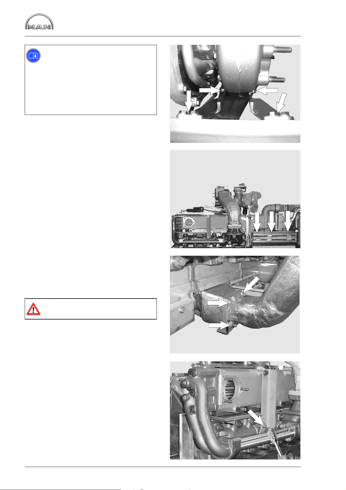
Removing and installing the exhaust manifold
Note:
The following text describes the removal
and fitting of the exhaust pipe in the
D 2876 LUE 601 / 602 / 603 engines
with exhaust-gas recirculation.
The steps relating to the exhaust-gas recirculation do not apply the D 2876 LUE
604 / 605 / 606 engines
without exhaust−gas recirculation.
D Removing the turbocharger, see page 79
Removing the exhaust manifold
Fig. 1
Remove bracket for exhaust manifold (arrow).
Fig. 2
1
Remove mounting bolts for heat shield and take off
lower part of heat shield.
Fig. 3
Remove mounting bolts (arrow) from exhaust pipe
and exhaust manifold.
Remove exhaust manifold.
Danger:
The exhaust manifold is heavy!
Fig. 4
2
3
Remove pipes and brace (arrow) for exhaust−gas
recirculation.
4
80
Page 83

Removing and installing the exhaust manifold
Fig. 5
Before unscrewing all securing bolts, if appropriate
replace 2 bolts by stud bolts as guides.
The stud bolts with thread M10 have been produced by MAN.
Danger:
The exhaust manifold is heavy!
Installing exhaust manifold
Fig. 6
Before fitting the exhaust pipe, screw in 2 stud
bolts as a guide.
5
Bolt guard plate and exhaust manifold together,
inserting new gaskets between guard plate and
exhaust manifold (bead must face guard plate).
Refit exhaust-gas elbow with brace, turobcharger,
pipes for exhaust-gas recirculation and heatshield.
6
81
Page 84

Removing and fitting exhaust-gas recirculation (EGR) module
Pneumatic cylinder
Fig. 1
Caution:
If the pneumatic cylinder is changed set
the ball head À so that it is hooked up
with approx. 4 mm pre-load with the shutoff flap Á closed.
Removing EGR module
D Removing the turbocharger, see page 79
D Remove exhaust manifold, see page 80
D Drain off coolant, see page 42
D Detach air line from pneumatic cylinder
1
2
1
Fig. 2
Remove pipes and brace (arrow) and coolant elbow for exhaust-gas recirculation (EGR).
Fig. 3
Remove mounting bolts for exhaust-gas recirculation line À and coolant elbow Á.
Take off exhaust-gas recirculation elbow and coolant elbow.
2
1
2
3
Fig. 4
Remove mounting bolts for EGR module and take
off EGR module.
4
82
Page 85

Removing and fitting exhaust−gas recirculation (EGR) module
Fitting EGR module
Fig. 5
To refit the EGR module follow the removal procedure in reverse.
D Position the EGR module and secure it with the
mounting bolts
D Refit exhaust-gas recirculation line, pipes and
coolant elbow with new seals
D Installing the exhaust manifold and turbo-
charger
D Connect up air line to pneumatic cylinder
D Fill coolant, see page 42
5
Stripping the EGR module
D Remove EGR module, see page 82
Caution:
Do not strip the exhaust-gas pipes / heat
exchanger housing unit as otherwise the
sealing between the gas-carrying and
coolant-carrying components is no longer
guaranteed.
Leaks between these components can
cause coolant to get into the cylinders
and thus lead to “water hammer”.
Fig. 6
Remove bolts from butterfly valve housing À and
from valve housing Á and take off both housings.
The check valves are under the valve housing and
can be changed if necessary.
1
6
2
Reassembling the EGR module
Position butterfly valve housing and valve housing
with new gaskets, secure them with the mounting
bolts and tighten the bolts to the specified torque.
Refit EGR module, see page 83.
83
Page 86

Turbocharger, troubleshooting
Before replacing the turbocharger, perform the following checks
It is frequently the case that with excessive engine oil consumption, low power or abnormal intake and/or
exhaust noise the turbocharger is replaced.
Subsequent inspections by the manufacturer of the supposedly defective parts frequently prove the turbochargers to be in working order.
To ensure that only defective turbochargers are replaced in future, the following checks must be carried out
beforehand:
In the case of excessive oil consumption
− check the air filter for soiling
− the intake system for reductions in diameter and leaks.
All of these cause higher oil consumption due to the increased vacuum.
− Check the outside of the turbocharger for traces of oil.
Oil consumption caused directly by the charger depends on the bearing wear and leads relatively quickly to
mechanical damage.
In the case of unsatisfactory engine power
A requirement for a satisfactory level of engine power is setting in accordance with regulations
− start of fuel delivery
− and of the valve clearance
− speed adjustment (pedal value)
The following must also be checked
− the compression pressure
− soiling of the air filters
− the intake system for reductions in diameter and leaks
− the exhaust system for damage and leaks
− the fuel delivery quantity is to be checked by measuring the fuel return
If these checks do not lead to detection of a possible cause, the turbocharger must be checked for
− coking in the turbine area leading to sluggishness of the rotor assembly(can be remedied by axial move-
ment)
− coarse dirt in the compressor area
− damage caused by foreign bodies
− scraping of the rotor disk on the casing.
In the case of coarse dirt, the compressor side must be cleaned and the bearing clearance checked.
Caution:
Do not damage the light-alloy compressor wheel.
In the case of abnormal intake and exhaust noise
− Check the intake and exhaust system in the area of the charge group.
Damaged gaskets lead to false diagnosis of a defective turbocharger; these must be replaced.
− If the abnormal noise is still present, replace the turbocharger.
Mechanically perfect turbochargers do not generate any noise!
84
Page 87
Turbocharger, troubleshooting
In the case of oil accumulation in charge-air lines and charge-air cooler
Slight oil accumulation due to oil spray in the charge−air system is a result of the design and is desirable.
The oil mist is required to lubricate the intake valve seats.
If more oil accumulates than is normal, i.e. to the extent that oil pockets develop e.g. in the lower air box of
the intercooler, this can lead to oil disintegration or uncontrolled engine racing when the oil is separated. In
such cases, remove the cause.
Possible causes:
− Oil overfilling of the engine.
D Check whether the correct dipstick and guide tube combination is fitted.
− Use of unsuitable engine oil (see brochure “Fluids and lubricants”)
− Operation of the engine on non-permitted inclines.
− Excessive crankcase pressure, e.g. due to defective oil separator valve (crankcase breather) or piston
ring wear.
Compressor coking
This can occur when the charge-air temperature is permanently high, for example when the engine is constantly run at full load.
Coking leads to a reduction in the charging pressure, but not to drops in power or poorer acceleration characteristics.
Coking can lead to increased exhaust haze.
In the case of compressor coking:
− Remove the compressor housing without tilting it
D If it jams, the compressor wheel blades may get damaged or bent and the resulting imbalance may
destroy the turbocharger.
− Remove coking from the compressor housing using coke-dissolving cleaner.
Danger:
Under no circumstances should cleaner be sprayed in while the engine is running
− ineffective
− danger of accident!
− In problem cases, use oil types that are less likely to lead to compressor carbonisation (see publication
“Fuels, Lubricants and Coolants for MAN Diesel Engines”).
85
Page 88
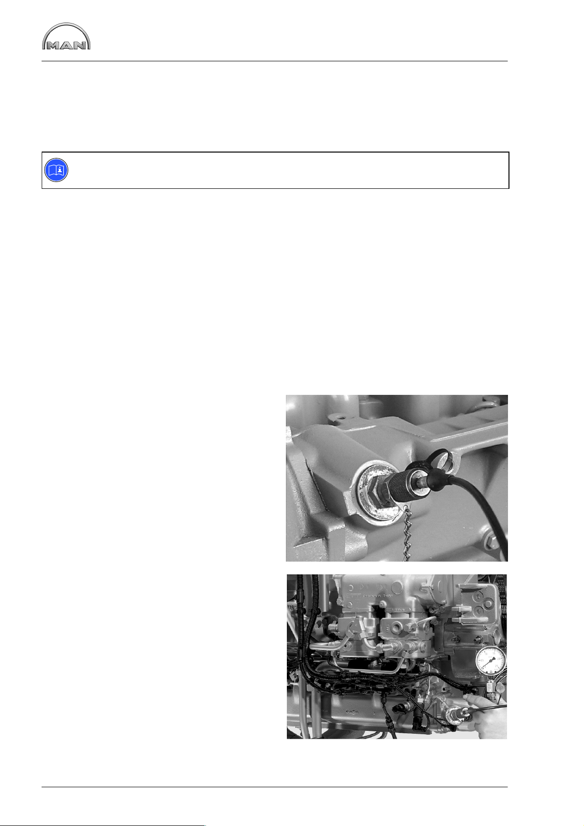
Checking charging pressure
Sufficient boost pressure is essential to ensuring full power output and clean combustion.
Checking the boost pressure helps to detect damage to the turbocharger and leaks in the intercooler and in
the charge-air pipes.
Extreme operating conditions (full-load operation and high air temperature) and the use of unsuitable engine oils (see also publication “Fuels, Lubricants and Coolants for MAN Diesel Engines”) may give rise to
deposits on the compressor and in the intercooler, resulting in a reduction in boost pressure.
Note:
The charge-air pressure can be read out also via the MAN Cats diagnostic system.
Preconditions for measurement
The start of fuel delivery and valve clearance must be set as specified and the engine must be at normal
operating temperature.
Charge-air pressuer:
No generally applicable target value for charging pressure can be given, as the installation conditions exert
an influence.
The target value is the value determined on commissioning of the engine and reported in the commissioning log.
Specific instructions during measurement
Based on various atmospheric reference conditions during the measurements and on tolerances of the
pressure gauges used, deviations of max. $100 hPa ($100 mbar) are permitted.
Fig. 1
The measuring connection for checking the
charge−air pressure and the charge−air temperature is located in the intake pipe at the point where
the flame−starter sheathed−element glow plug is
screwed in.
Remove flame-starter sheathed-element glow plug
see page 41.
Connect up pressure gauge (if necessary using a
suitable threaded pipe as adapter).
1
Fig. 2
Measure the boost pressure downstream of the
intercooler at rated engine speed and full load.
86
2
Page 89

Removing and installing the turbocharger
Remove turbocharger
Fig. 1
Remove oil supply À and return lines Á.
Fig. 2
Afterwards remove the pipe leading to the crankcase breather  the spring band clamp from the
air compressor intake pipe à and the V-clamp from
the charge-air elbow Ä and take off the pipes.
2
1
1
Fig. 3
Remove the nuts Å from the turbocharger flange.
Take off turbocharger.
Note:
When placing the turbocharger to one
side, ensure extreme cleanliness to prevent penetration of dirt and foreign
bodies.
3
5
4
2
6
3
87
Page 90

Removing and installing the turbocharger
Install the turbocharger
Fig. 4
The turbocharger is fitted in reverse order.
On assembly, new gaskets and new self-locking
nuts are to be used.
Before connecting the oil supply line, fill the bearing housing with fresh engine oil.
Check all the connections for leaks and to ensure
they are not subjected to strain.
4
Fig. 5
Note:
Ensure that the clamping area of the
hose is always behind the bead of the
pipe.
À Pipe
Á Hose
 Hose clamp
à Distance
Ä Bead on pipe
1 2 3
5 4
5
88
Page 91

Measuring the axial / radial clearance or the turbocharger shaft
D Removing the turbocharger, see page 87
D Mark turbine housing relative to the bearing
housing and remove turbine housing
Axial clearance
Fig. 1
Apply dial gauge holder and dial gauge under preload to shaft end face of the turbine wheel as
shown. Apply the dial gauge with initial tension on
the face of the shaft end of the turbine wheel.
Press the rotor shaft against the dial gauge, read
off and note the value. Press the rotor shaft in the
opposite direction, read off and note the value.
The difference between the values obtained is the
axial clearance.
If the play exceeds the permissible value, exchange turbocharger.
1
Radial clearance
The radial clearance is measured only on the turbine side with a dial gauge or feeler gauge.
Fig. 2
Dial gauge:
Place the measuring tip of the dial gauge to the
side of the hub, press the turbine wheel to the dial
gauge, read off and note the value.
Press the turbine wheel in the opposite direction,
read off and note the value. The difference between the values obtained is the radial clearance.
Measure at several points.
If the play exceeds the permissible value, exchange turbocharger.
2
89
Page 92
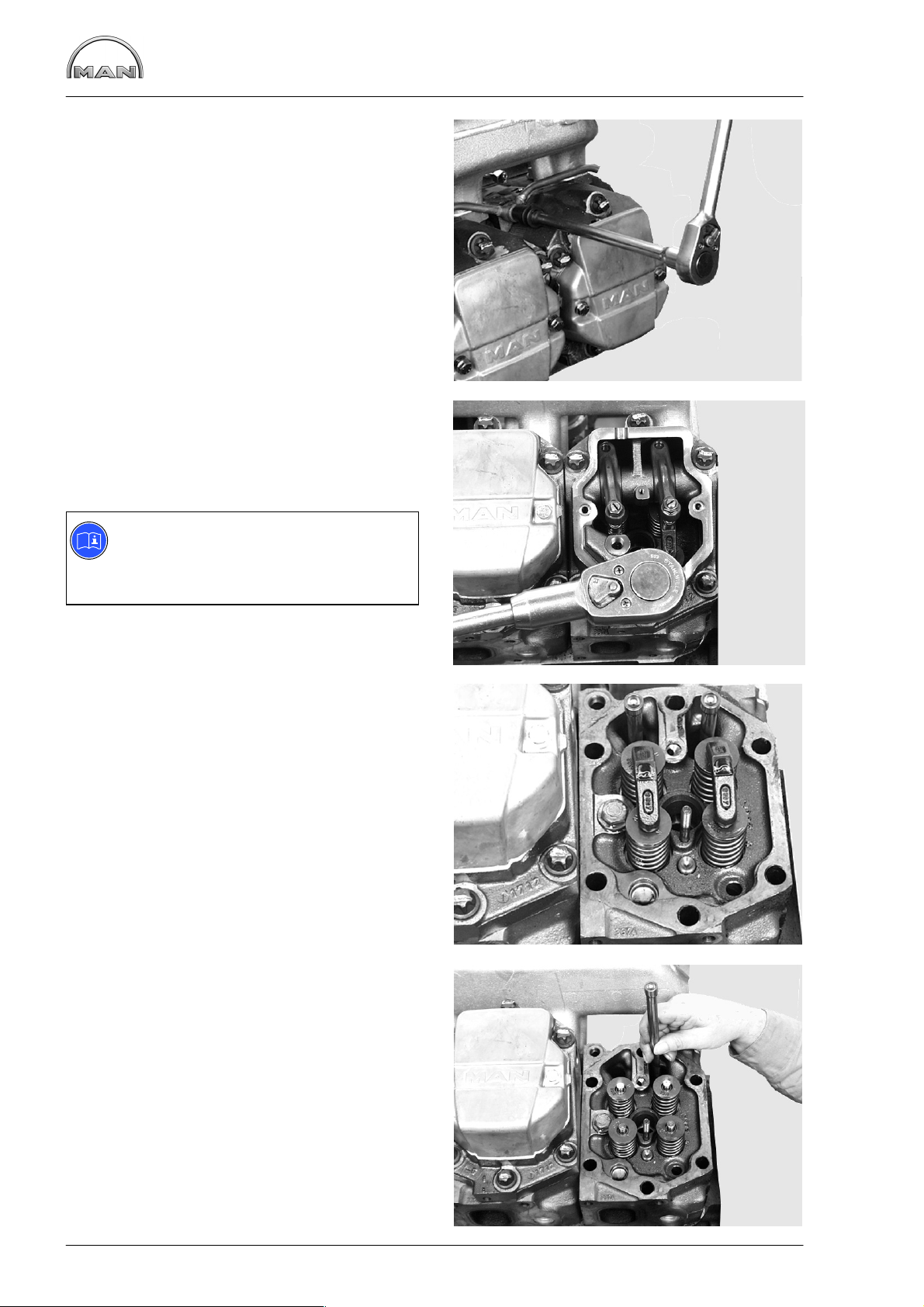
Removing and installing the cylinder head
Removing the cylinder head
D Draining off coolant, see page 42
D Remove injection nozzles, see page 30
D Removing EGR module, see page 82
D Removing intake manifold, see page 79
D Removing exhaust manifold, see page 80
Fig. 1
Remove the coolant bleed pipe.
Remove the cylinder head covers.
Fig. 2
Back off the valve adjusting screws.
Release and remove the cylinder head bolts in reverse order of tightening.
1
Note:
Use a reinforced screwdriving machine to
loosen and tighten the cylinder head
bolts.
Fig. 3
Remove rocker arm bearing housing.
2
3
Fig. 4
Remove the valve bridges.
Take out the tappet push rods.
4
90
Page 93

Removing and installing the cylinder head
Fig. 5
Remove the cylinder head and cylinder head
gasket.
Check whether cylinder head sealing face and cylinder block are plane using a straight edge.
Caution:
The cylinder head sealing face must not
be reworked.
Note specified nozzle projection and valve recess
(see “Service Data”).
Fitting the cylinder head
Fig. 6
Before fitting, clean and blow out the tapped holes
in the crankcase. Clean the sealing faces on the
cylinder head and on the crankcase.
5
Lay the new cylinder head gasket in place, ensuring that the hole patterns match up, and place the
cylinder head on top.
Each cylinder head is fixed in position with 2 fitting
sleeves.
Fig. 7
Check the push rods for distortion. When inserting
the tappet push rods, ensure that they fit in the
socket of the valve tappet.
Insert the valve bridges with the cut-through sides
Á facing the push rods.
Fig. 8
6
1 2
7
Apply a thin bead of “Loctite 5900” sealing compound to seal the rocker arm bearing housing.
Caution:
The bore hole (À in Fig. 7) must be kept
clear for the oil supply!
8
91
Page 94

Removing and installing the cylinder head
Fig. 9
Fit the rocker arm bearing housing, inserting the
rocker arm ball pins into the tappet ball sockets.
Fig. 10
Check cylinder−head bolts for max. permitted
length (see “Service Data”). Removed bolts can be
reused if the max. permitted length is not exceeded.
Before inserting the cylinder head bolts, apply engine oil to the threads and coat the contact faces
of the bolt heads with “Optimoly White T” installation paste.
Fig. 11
Tighten the bolts according to the rotation angle
method. Observe the tightening sequence, prescribed tightening method, instructions and notes
on cylinder head bolts in the chapter “Service
Data”.
9
Fig. 12
Note:
To avoid any distortion between the cylinder heads and exhaust manifolds, we
recommend proceeding as follows:
D Fit the cylinder head gaskets and cylin-
der heads.
D Turn the head bolts a few thread turns.
D Secure steel ruler (special tool) with
ground face on the exhaust side;
tightening torque for mounting bolts 20
Nm.
If a steel ruler is not available, mount
exhaust manifold and tighten to 20 Nm.
D Tighten the cylinder−head bolts as pre-
scribed.
D Unscrew the straightedge.
D Tighten the exhaust pipe and intake
manifold with the prescribed torque.
10
11
Set valve clearance, see page 94.
Fit injection nozzle.
Fit the cylinder head cover with a new gasket.
Fitting EGR module.
Fit coolant bleed line with new seals.
Fill up with coolant, see page 42.
12
92
Page 95

Removing and installing the cylinder head
General notes
The sealing effect of the cylinder head gasket depends mainly on whether the required initial tension of the
cylinder head bolt is actually achieved and retained.
Use calibrated torque wrenches to tighten the cylinder head bolts. The specified final torque must be maintained for at least 5 seconds when it is applied. When using snap-type torque wrenches, tighten the bolts
gradually as otherwise the torque selected will not be fully transferred to the bolts.
Observe the notes on the usability of cylinder-head bolts, tightening sequence, and prescribed tightening
method in the chapter “Service Data”.
Tightening
“Tightening” is defined as the initial tightening of newly fitted bolts that have not been tightened following a
repair - e.g. after replacement of the cylinder head gasket. Tighten cylinder head bolts while the engine is
cold, i.e. the crankcase is warm to the touch or colder.
Before inserting the cylinder−head bolts, apply engine oil to the thread (not the threaded hole) and coat the
seating surface of the bolt head with installation paste “Optimoly White T”.
Do not use oils or oil additives containing MoS
In the case of unoiled bolts, a significant amount of the tightening torque is converted into friction and is
thus lost for bolt pretensioning.
.
2
D To secure the cylinder heads, tighten the cylinder head bolts only slightly
D Align cylinder heads by screwing on the steel ruler (special tool). If a steel ruler is not available, use ex-
haust or intake manifold
D Tighten step by step in the correct order to specified torque/angle of rotation
Caution:
If individual bolts are tightened too much during preliminary tightening, the cylinder head is distorted.
The distortion cannot be cancelled out by continued tightening according to instructions!
93
Page 96
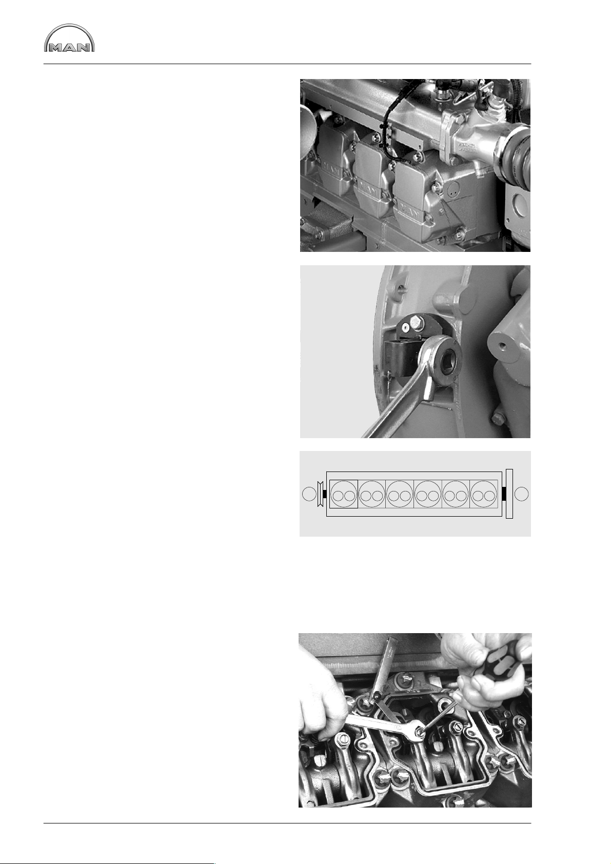
Setting the valve clearance
Fig. 1
Remove the cylinder head covers.
Fig. 2
An engine cranking device (special tool) may be
mounted also at the inspection hole of the flywheel
housing.
Use barring device to turn engine so that the piston in the cylinder to be set is at TDC and the all
valves are closed. At this point both inlet and exhaust valves will be open i.e. valves overlap.
1
Fig. 3
Valves are in crossover in cylinder:
1 5 3 6 2 4
6 2 4 1 5 3
Set valves on cylinder:
Arrangement of cylinders and valves
I Engine front end
II Flywheel side
A Exhaust valve
E Inlet valve
Fig. 4
Push feeler gauge between valve connection and
rocker arm. Loosen the locknut and turn the adjustment screw until the feeler gauge can be
moved with slight resistance
Tighten lock nut to the specified torque (see “Service Data”) using screwdriver to prevent adjusting
screw from turning. Check clearance again.
2
I
3
123456
EA EA EA EA EA EA
II
Refit cylinder head covers.
4
94
Page 97

Disassembling and Assembling Rocker Arm Mechanism
Disassembling rocker arm mechanism
D Remove cylinder head, see Page 90
Fig. 1
Clamp mounting plate Á (special
toolLEERER MERKER, item. 24) in a vice and bolt
the rocker arm bearing housing onto the mounting
plate.
The exhaust valve rocker arm shaft has a tapped
hole.
Screw adapter and impact puller À into this tapped
hole.
Fig. 2
Pull out the exhaust valve rocker arm shaft and
remove the rocker arm.
1
2
1
Fig. 3
Drive out the intake valve rocker arm shaft with a
suitable plastic mandrel.
Fig. 4
Remove the rocker arm shaft and rocker arm.
2
3
95
4
Page 98

Fig. 5
Disassembling and Assembling Rocker Arm Mechanism
À Rocker arm shaft for exhaust valves
Á Rocker arm shaft for inlet valves
 Rocker arm
Assembling rocker arm mechanism
Fig. 6 and Fig. 7
Recesses À in the rocker arm shafts serve to accommodate the cylinder head bolts Á.
Align the rocker arm shafts so that the holes for
the cylinder head bolts are kept free.
Lightly oil the shafts and O-rings.
21 3 3
5
1 2
Fig. 8
Press-in device for the rocker arm shafts (special
tools, item. 27.3, see page 169).
À Guide plate
Á Mounting bolts
 Press-in part “A” for exhaust-side shaft
à Press-in part “B” for intake-side shaft
6
7
1
2
96
8
3 4
Page 99
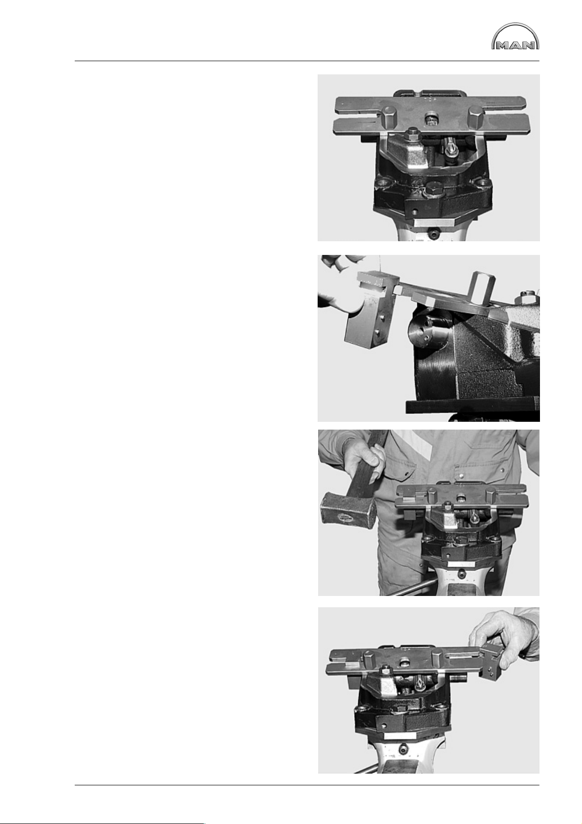
Disassembling and Assembling Rocker Arm Mechanism
Fig. 9
Bolt the guide plate onto the rocker arm bearing
shaft − with “TOP” facing the intake side.
Fig. 10
Insert press-in part “A” for the exhaust-side shaft
into the guide plate, ensuring that the alignment
pins fit into the shaft bores.
9
Fig. 11
Drive the rocker arm shaft fully home into the bearing housing.
Fig. 12
Insert press-in part “B” for the intake-side shaft into
the guide plate, ensuring that the alignment pins fit
into the shaft bores.
Drive the rocker arm shaft fully home into the bearing housing.
10
11
12
97
Page 100

Disassembling and Assembling Rocker Arm Mechanism
Fig. 13
Remove the press-in tool.
Check the rocker arms for ease of movement and
axial play.
13
98
 Loading...